1. Introduction
Fluxgate sensors are vector magnetometers with a wide range of resolutions from pT to mT. As the most sensitive magnetometer technology that does not require extensive cryogenics they are used for geomagnetic surveys, mineral exploration, aerospace and defense as well as medical applications [
1]. However, their bulky nature makes such sensors unfeasible for many industrial applications like magnetic position and orientation detection. Miniaturization of this inductive based technology is difficult as the sensitivity is directly proportional to the sensor dimension given by the number of windings and the cross section of the magnetic core [
2]. Fluxgate layouts based on planar technology [
3] have two advantages over their 3D counterparts: Fabrication is easy using cheap and available PCB technology [
4] and, despite their size, the planar form factor makes them potentially suitable for industrial system integration for applications like current sensing or angle detection. To improve the troublesome planar form factor, closed core structures were proposed based on symmetrical cores [
5]. Recent studies however, shed new light on such layouts [
6]. It is claimed that asymmetric double-core structures improve sensitivity while circumventing a symmetry problem that is not addressed in the original proposal. In this work, for the first time a direct comparison is attempted between single- and asymmetric double-core structures of similar geometries. It is the aim to determine the real benefits of the asymmetric structure with respect to sensitivity and power supply.
2. Fluxgate Mechanism and Planar Layout
A flux gate sensor typically comprises one excitation coil and two pickup coils that are coupled through a soft ferromagnetic core of high permeability. The excitation coil periodically drives the core in and out of saturation. An external field
H0 of interest is in superposition with the excitation field and shifts the characteristic non-linearity of the material magnetization which is detected by the pickup coils. In the Vacquier implementation two symmetric pickup coils detect opposing excitation fields, but aligned external fields. Within the differential signal the inductive part is eliminated and the resulting output voltage is given by the classical fluxgate equation,
Here
N denotes the number of turns of the pickup coils,
A is the core cross section and
µ(
t) the dynamic permeability
µ(
t) =
∂HB(
t). One of the most common methods to find
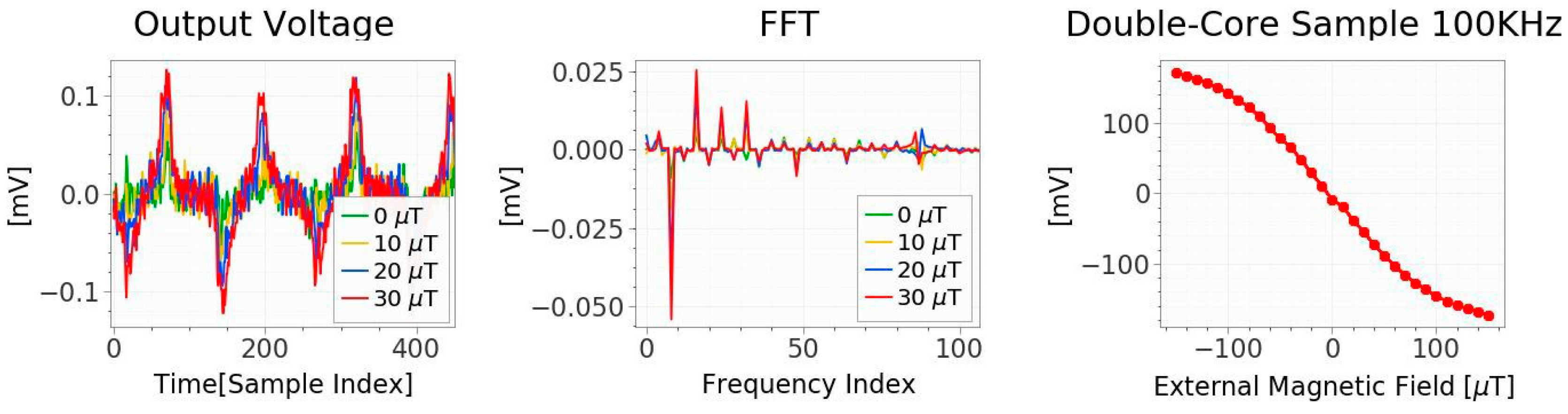
H0 from the output voltage (1) is by extracting the amplitude of the second harmonic which is also independent of temperature and other disturbances, [
7]. For better understanding
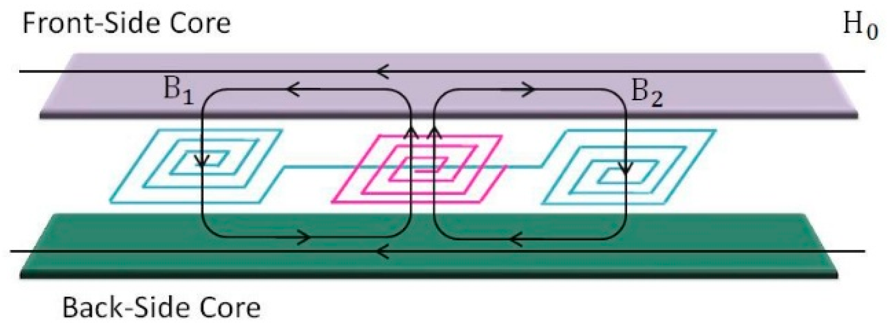
Figure 1 shows the measurements result of one setup. The planar layout chosen for this study is sketched in
Figure 2. The pickup coils lie adjacent to the excitation coil and one or two core sheets are symmetrically mounted from above and below. As laid out in [
6], symmetric cores must result in a cancellation of the signal. However, the double core structure must be beneficial for the efficiency of the magnetic circuit. It was therefore proposed to use different materials in the front and the back, one material that will saturate with a sharp magnetization bend and a second one that will enhance the field so that less excitation current is required thus enhancing sensitivity and reducing necessary power supply.
3. Sensor Fabrication
The Setup used for this research is based on a four-layer PCB with line trace width and spacing of 75 µm, thickness of 35 µm, resulting in a total PCB thickness of 500 µm and three adjacent coils of 60 windings respectively in a total structure size of 18
× 6 mm
2. For the core structures two materials were chosen: A cobalt-based film of Metglas 2714A [
8] with 15 µm thickness, relative permeability of
µr = 10
6 and saturation magnetization of
BS = 0.57 T and a ferromagnetic alloy VITROVAC 6155 U55 [
9] with lower permeability of
µr = 1330, saturation magnetization of
BS = 0.99 T and foil thickness of 23 µm. In this study, the fast saturation of the first material (high permeability) is used for the fluxgate effect in the single and the double core structure, while the second material is only used in the double core structure to focus the magnetic field. It is not expected to reach saturation in the perfomred experiments.
Much effort was directed towards fabrication of a high precision setup. To cut the highly corrosion resistant cores pico-second laser cutting was applied with minimal energy input to conserve the magnetic material properties. Therefore a scanner optics with multiple irradiation of the contour with a preselected feeding speed of 250 mm/s was applied. As cutting laser the type neoMOS 10 ps was used, where the pulse energy was 25 µJ with a laser beam diameter of 10 µm and a repetition rate of 50 kHz.
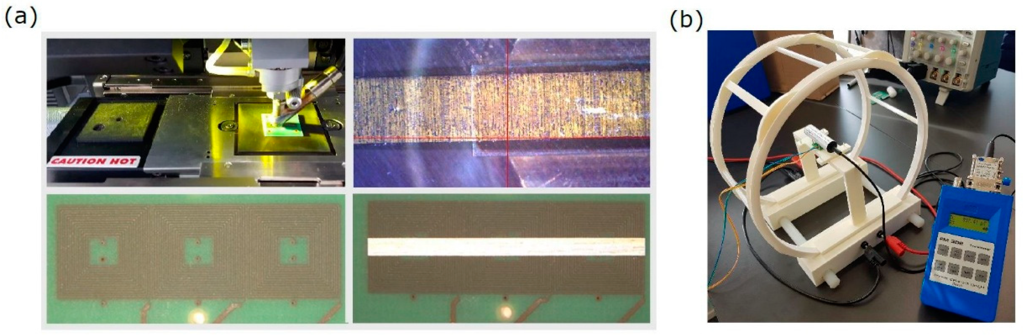
To precisely align and attach the precision-cut core films to the sensor structure a Micro Assembling Station (FINEPLACER® Lambda) was used. In the middle of the structures, an array of non-conductive cyanoacrylate adhesive droplets with a diameter of 200 ± 10 µm was precisely dispensed. By means of the mechanical arm, the ferromagnetic film was picked and precisely positioned above the designated area on the PCB (precision of ±1 µm) and subsequently adhesively-bonded with a small force of 4 N for 15 s. The whole constructing process was carried out at room temperature.
Figure 3 a shows the actual system layout and the bonding procedure.
4. Experimental Setup and Data Analysis
To test and evaluate the fabricated sensors they are put in the homogeneous field of a Helmholtz coil pair together with a precision reference sensor of type AS-UAP GEO-X from Project Electronics with nT resolutions as shown in
Figure 3b. A signal generator supplies the excitation coil with a variable, defined sinusoidal current. The required power supply can then be determined from the impedance of the excitation coil.
The measurements were performed with an oscilloscope, recording the output voltage of the sensor over more than 500 periods in 10000 samples. A Fourier analysis was performed in order to extract the second harmonic of output signal which has a direct relation to external magnetic field, as shown in
Figure 1. The large number of periods was chose to increase the resolution in the frequency domain in order to have a very precise access to the second harmonic of output voltage.
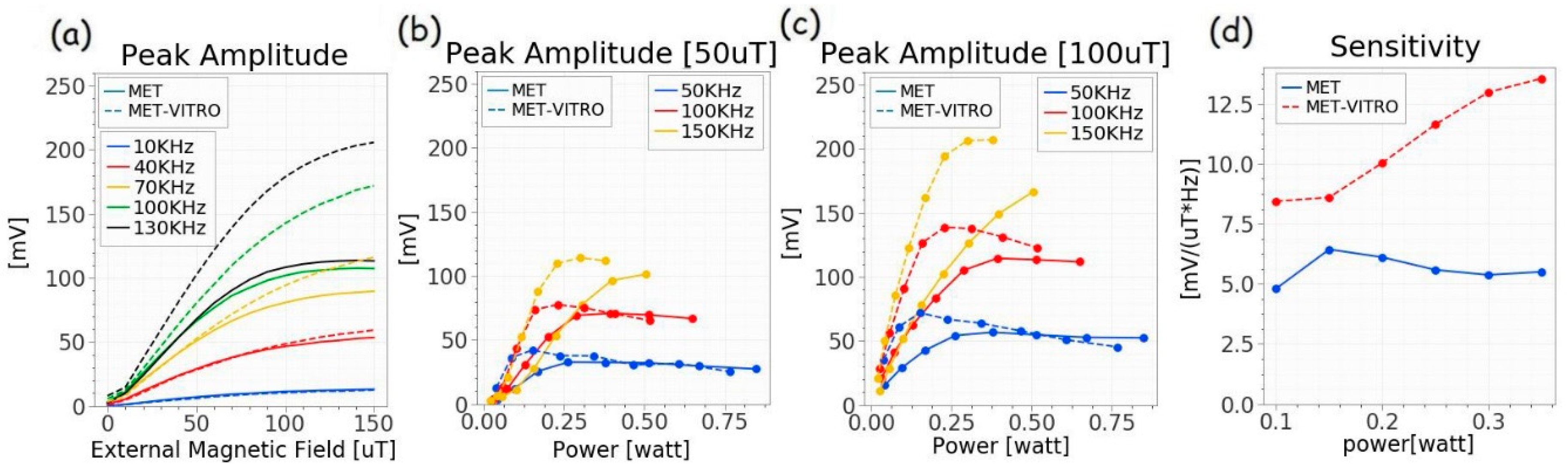
The output signal of the sensor (peak height of the second harmonic) is a function of three parameters of interest, the external magnetic field, the power supply and the driving frequency. The sensor sensitivity is given by the change of the peak over the supply current. In most setups the output voltage (1) is directly proportional to the frequency, as long as eddy currents can be neglected and the external field is sufficiently small, which allows us to display the sensitivity in terms of peak height over power supply and frequency.
Figure 4a shows the peak amplitude of single and double core sensors from different values of the magnetic field, for a similar supply voltage of
Vpp = 3.3 V. The higher potential sensitivity of the double-core structure is clearly visible, however, as the double core structure has a higher impedance and uses less power, the comparison is flawed. In
Figure 4b,c the peak amplitudes are displayed as functions of the supplied power.
Finally, for direct comparison, the sensitivities of the sensors were calculated for small external fields below 100 µT (linear regime) and the results are shown in
Figure 4d. It can be seen that for a same supply power the asymmetric double core structure features sensitivities that are up to a factor of 2 higher.
5. Conclusions
Comparable single and double-core fluxgate structures have been realized by precision fabrication. The samples were investigated in detail and a comprehensive comparison was performed. All prototypes of the double-core samples show improved sensitivity, up to a factor of two for similar power requirement, when compared to their single core counterparts. The proposed implementation shows the potential benefits of asymmetric double core structures, however, it can be expected that alternative material combinations and geometries will further improve this sensor.
Author Contributions
Conceptualization and Methodology, M.O. and M.L.; Experimental Setup, N.N., A.R. and M.L.; Experimental Investigation and Analysis, N.N., M.L. and M.O.; Writing, N.N. and M.O.
Funding
This project has been supported by the COMET K1 centre ASSIC Austrian Smart Systems Integration Research Center. The COMET—Competence Centers for Excellent Technologies—Program is supported by BMVIT, BMWFW and the federal provinces of Carinthia and Styria.
Conflicts of Interest
The authors declare no conflict of interest.
References
- Ripka, P.; Záveˇta, K. Chapter Three Magnetic Sensors: Principles and Applications. Handb. Magn. Mater. 2009, 18, 347–420. [Google Scholar]
- Pérez, L.; Lucas, I.; Aroca, C.; Sánchez, P.; Sanchez, M.C. Analytical model for the sensitivity of a toroidal fluxgate sensor. Sens. Actuators A Phys. 2006, 130, 142–146. [Google Scholar] [CrossRef]
- Vincueria, I.; Tudanca, M.; Aroca, C.; Lopez, E.; Sanchez, M.; Sanchez, P. Flux-gate sensor based on planar technology. IEEE Trans. Magn. 1994, 30, 5042–5045. [Google Scholar] [CrossRef]
- Baschirotto, A.; Dallago, E.; Malcovati, P.; Marchesi, M.; Venchi, G. Development and comparative analysis of fluxgate magnetic sensor structures in PCB technolozgy. IEEE Trans. Magn. 2006, 42, 1670–1680. [Google Scholar] [CrossRef]
- Ripka, P.; Choi, S.; Tipek, A.; Kawahito, S.; Ishida, M. Symmetrical core improves micro-fluxgate sensors. Sens. Actuators A Phys. 2001, 92, 30–36. [Google Scholar] [CrossRef]
- Lenzhofer, M.; Ortner, M.; Navaei, N.; Schulz, G.; Stahr, J. Investigations of the magnetic circuit within a planar double core Fluxgate Sensor structure. Sensor Test 2018, 371–374. [Google Scholar]
- Ripka, P. Advances in fluxgate sensors. Sens. Actuators A Phys. 2003, 106, 8–14. [Google Scholar] [CrossRef]
- Metglas™, Magnetic Alloy—Product Brochures. 2017. Available online: http://www.metglas.com/tech/ (accessed on 1 May 2018).
- VAC, Soft Magnetic Materials and Semi-finished Products, PHT-001, VACUUMSCHMELZE. 2002. Available online: www.vacuumschmelze.com (accessed on 1 May 2018).
| Publisher’s Note: MDPI stays neutral with regard to jurisdictional claims in published maps and institutional affiliations. |
© 2018 by the authors. Licensee MDPI, Basel, Switzerland. This article is an open access article distributed under the terms and conditions of the Creative Commons Attribution (CC BY) license (https://creativecommons.org/licenses/by/4.0/).


