Abstract
Assistant robots need a tactile sensing system. We propose a tactile sensor head with a nerve-net sensing system which measures force, temperature and heat flow with a heater simultaneously on a robot finger. For accurate heat flow measurements, it is necessary to stabilize the contact conditions between the sensor head and an object. A sensor stick which consists of the sensor head and an actuator was fabricated to control applied force. Heat flow measurements in three materials of different thermal conductivities such as polyethylene, glass and Aluminum were made with the sensor stick. As a result, three materials were discriminated clearly by heat flow peak values, saturations values and time constants. The tactile sensor stick with temperature measurement and force control is useful to discriminate materials of objects.
1. Introduction
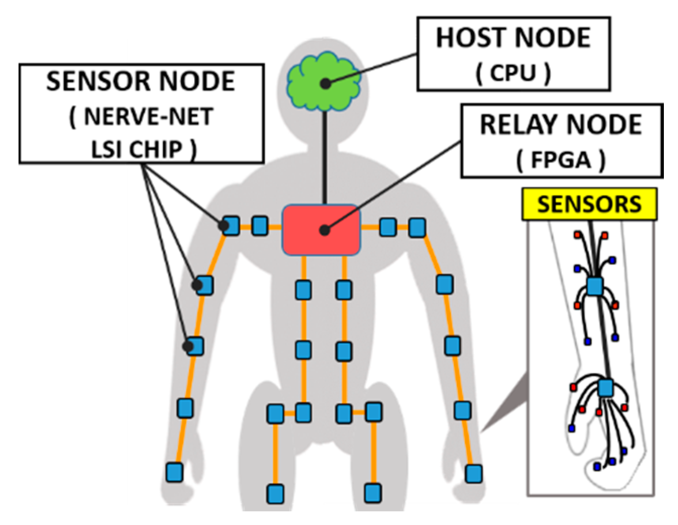
Assistant robots are expected to work together with humans in housework and nursing places. In this case, the robots work near a human being. Therefore, robots are required to consider safety in contact with humans and objects. Tactile sensors play important roles to communicate with humans and to protect them in collision contact for safety. In a tactile sensing system, it is necessary to cover the entire robot body with many sensors. Therefore, there are problems that wiring and data amount increase. Research to reduce wiring for sensors was conducted [1,2]. Especially sensing of the fingertip is important, and researches on sensors for robot’s fingertips were actively conducted [3,4]. Several sensors that acquired multiple sensor data such as force and heat were also studied [5,6]. Human tactile sensing is able to estimate materials by heat flow during contacts. Robots also should estimate substances such as metal, wood, rubber, etc. by heat flow. We propose a sensor head that measures force, temperature and heat flow with a nerve-net sensing system (Figure 1). The sensor head measures heat flow with a heater, nerve-net LSI chip [7], and plural thermistors. For stable heat flow measurement, it is necessary to stabilize the contact state between the sensor head and objects. We have developed a sensor stick for measuring stable heat flow under force control. The heat flows of three objects with different thermal conductivity were measured with the sensor stick.

Figure 1.
Image of Nerve-net tactile sensing on robot.
2. Nerve-Net Sensing System
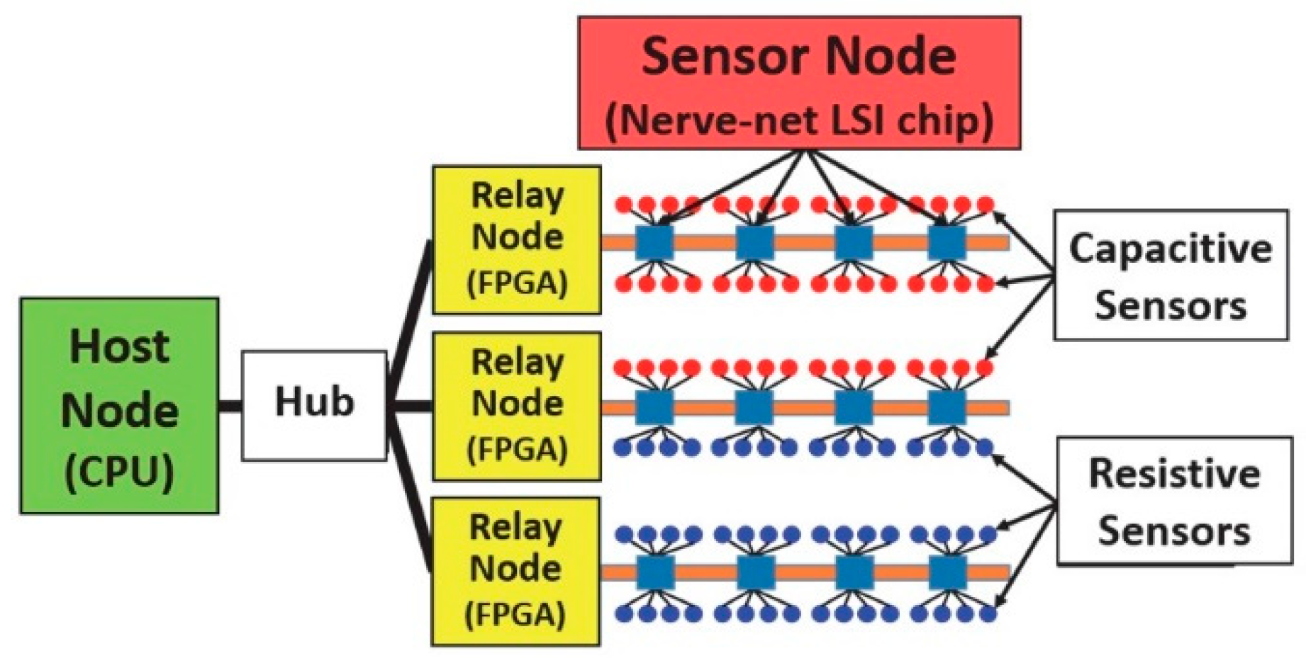
The nerve-net sensing system consists of three levels of host nodes, relay nodes, and sensor nodes (Figure 2). A CPU, an FPGA (Field Programmable Gate Array) and a nerve-net LSI chip works as the host node, the relay node, and the sensor node, respectively. The CPU and FPGAs are connected with a hub and USB cables, FPGAs and LSIs are connected by special bus lines. The bus lines consist of four lines: 3.3 V, 1.2 V power lines, ground and signal lines. A plurality of capacitive type and resistance type sensors can be connected to one of the nerve-net LSI chip serving as the sensor node. Analog signals from the sensors are digitized and outputted to the bus line. It is possible to arrange many sensors on the bus lines. Since the bus line becomes a belt-like shape, sensors are easily mounting and wiring on curved surfaces of robots. Up to 255 sensor nodes can be connected on a bus line corresponding to one relay node and up to 127 relay nodes can be connected to the host node. As this system as a whole, 255 × 127 = 32,385, that is, about 30,000 sensor nodes are connected and designed to be managed by the host node.
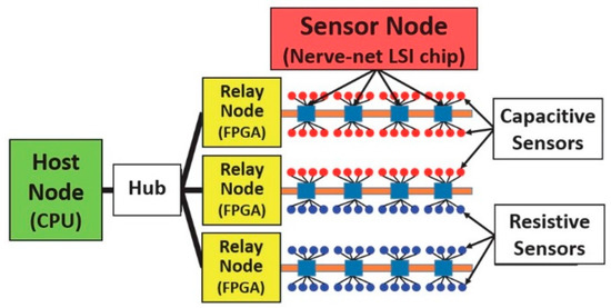
Figure 2.
Nerve-net sensing system.
3. Design of a Force and Thermal Sensor Head
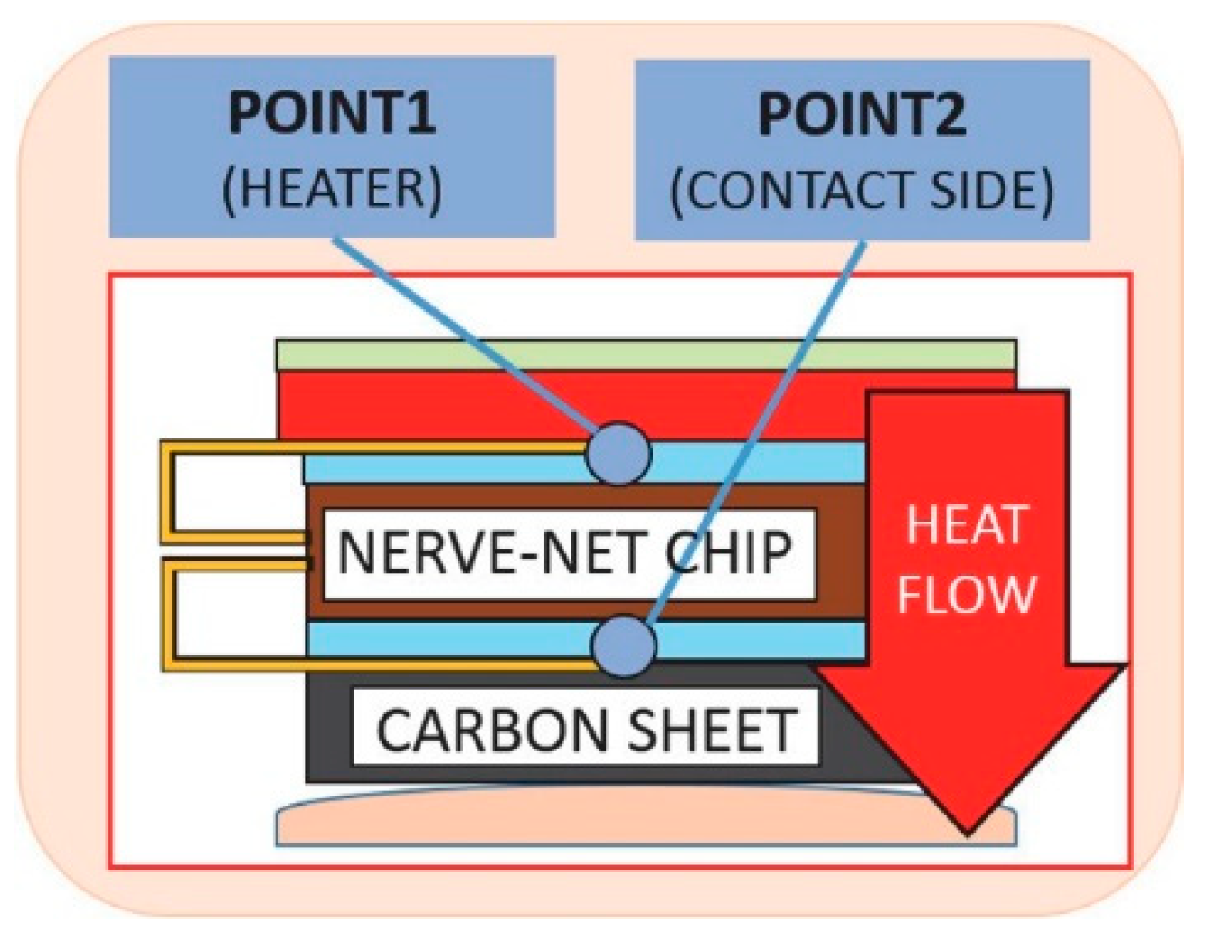
Using the nerve-net sensing system, we proposed a sensor head which simultaneously measures force and thermal quantities. The sensor head has two parts. One is a thermal sensing part, which is close to the contact target and has a heater. Another is a force sensing part, which is set in a portion far from the contact surface. The sensor head consists of a resistance type force sensor, a heat insulator, a heater, a nerve-net LSI chip, two thermistors and a carbon sheet (Figure 3). The size of the sensor head is 9 × 9 × 9 mm3 and it can be attached to a fingertip of robot fingers. Applied forces are detected by the force sensor. Temperatures are detected by thermistors. Heat flow rates are obtained from the temperature difference between the two points of Point1 and Point2 (Figure 4). The nerve-net LSI chip has two roles. The first is to collect sensor data of two temperatures by two thermistors and a force by the force sensor. The second is to create a temperature difference as a thermal resistor. The nerve-net LSI chip is packaged in a ceramic of good heat transfer coefficient. The heater is used to actively generate a temperature difference between the sensor head and the object to be measured. The face of the sensor head is covered with a soft and high thermal conductivity carbon sheet to prevent injury to an object and to make good contact with one.
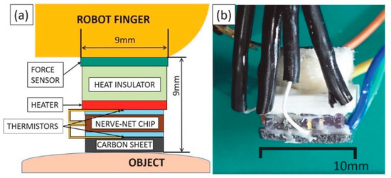
Figure 3.
(a) Structure model of sensor head; (b) Photograph of sensor head.
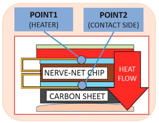
Figure 4.
Heat flow measurement points.
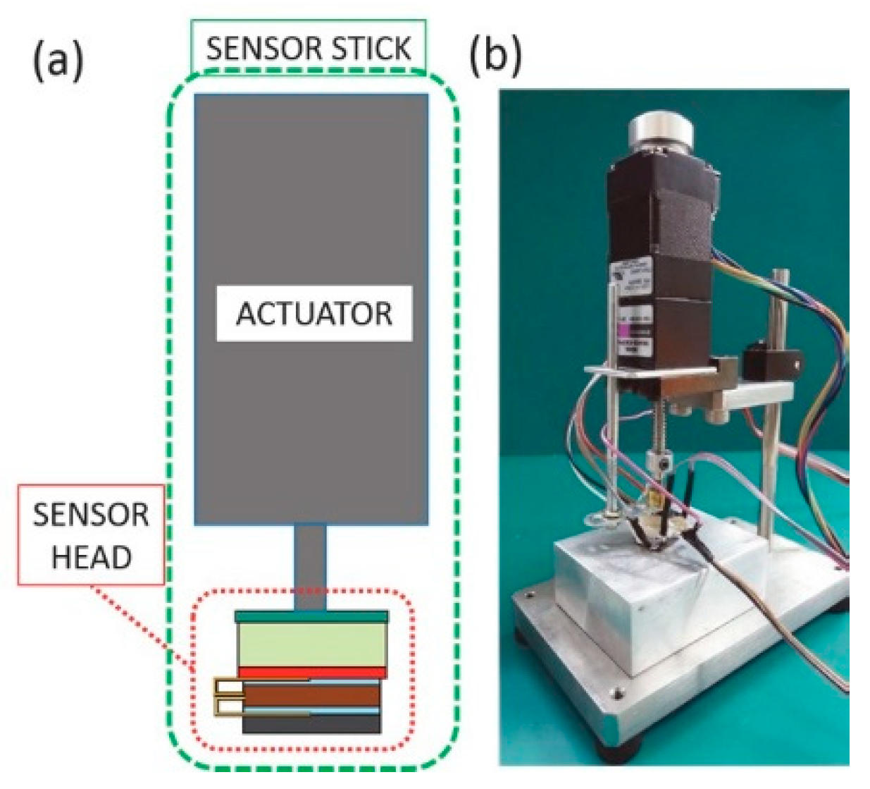
4. Design of a Sensor Stick
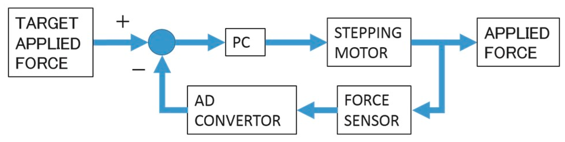
By stabilizing the contact state between the sensor head and the object, we can stably measure the heat flow rate. A sensor stick was made to control applied force in heat flow measurement. The sensor stick consists of a sensor head, an actuator, and a supporting stand (Figure 5). The sensor stick size is 60 × 100 × 150 mm3. The sensor stick performs feedback force control with force data obtained from the sensor head through an AD converter. In the proportional feedback control, the stepping motor movement is divided in seven stages by a deviation between the target applied force and the applied one (Figure 6).
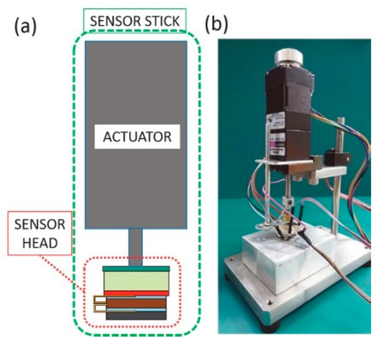
Figure 5.
(a) Structure model of sensor stick; (b) Phtograph of sensor stick.

Figure 6.
Control block diagram of sensor stick.
5. Heat Flow Measurement by the Sensor Stick and Results
5.1. Heat Flow Measurement
Three objects with different thermal conductivities of PE (polyethylene), glass and Al (aluminum) blocks were used to measure the heat flows by the sensor stick. The thermal conductivities of PE, glass and Al are 0.4, 1.0, 240 W/m·K, respectively. The block sizes were 40 × 50 × 20 mm3 for PE and Al, and 70 × 70 × 17 mm3 for glass (Table 1). In the measurement, the sensor head was kept high temperature by heating of 0.55 W. After the temperature of the sensor head up to 65~70 °C, the sensor head was brought into contact with the object for 180 s by the actuator. At the time of contact, the actuator maintained a constant contact force at 3.0 ± 0.2 N.

Table 1.
Measured temperatures and heat flows with polyethylene, glass, and aluminum.
5.2. Result
The temperature changes and heat flow rate ones by the contact at room temperature of 26 °C were shown in Figure 7a,b, respectively. The temperatures of point1 and point2 were decreased rapidly after contact and saturated (Figure 7a). The saturation temperatures (point2) of PE, glass and Al were 55.6, 49.3, and 35.0 °C, respectively. The larger thermal conductivity objects showed lower saturation temperatures. Time constant of temperature (point2) of PE, glass and Al were 19.6, 21.2, and 5.7 s. No distinctive relationship was found between thermal conductivity and temperature time constant (Table1). The heat flow rates showed peeks at about 10 s after the contact and saturations after about 120 s (Figure 7b). The saturation value of heat flow rate was defined as the average value between from 120 to 180 s after contact. The time constant of heat flow rate was defined as the time of 63.2% attenuation from the peak value to the stationary value. The peak values of heat flow rate of PE, glass and Al were 0.43, 0.49, and 0.91 W, respectively. The saturation values of PE, glass and Al were 0.29, 0.33, and 0.39 W. Time constant of PE, glass and Al were 16.3, 18.7, and 23.4 s. The larger thermal conductivity objects showed the higher peaks, larger saturation temperatures and longer time constant (Table 1). The three objects were discriminated clearly after contact of the sensor head by four means as saturation temperatures, heat flow rate peaks, heat flow rate saturations and time constants of heat flow rate.
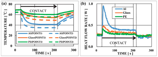
Figure 7.
(a) Temperature changes during heat flow measurement; (b) Heat flow rate changes during heat flow measurement.
6. Conclusions
In order to mount tactile sensing to robot fingers, we proposed the force and thermal sensor head that measures force and temperatures simultaneously with the nerve-net sensing system. The sensor stick was also proposed to measure heat flows with the force control system, which stabilized contact state with the force sensor and actuator. In heat flow measurements with the sensor stick, the peak values of heat flow rate of PE, glass and Al were 0.43, 0.49, and 0.91 W, respectively. The saturation values of PE, glass and Al were 0.29, 0.33, and 0.39 W. Three objects of PE, glass, and Al were discriminated clearly by four means of saturation temperatures, heat flow rate peaks, heat flow rate saturations and time constants of heat flow rate. By the sensor stick measurements, heat flow measurements by the sensor head with the nerve-net sensing system help robots determine materials by finger contact.
Acknowledgments
Parts of this work were supported by the New Energy and Industrial Technology Development Organization (NEDO), and by the Special Coordination Funds for Promoting Science and Technology.
References
- Lee, H.K.; Chang, S.I.; Yoon, E. A Flexible Polymer Tactile Sensor: Fabrication and Modular Expandability for Large Area Deployment. J. Microelectormech. Syst. 2006, 15, 1681–1686. [Google Scholar] [CrossRef]
- Schmitz, A.; Maiolino, P.; Maggiali, M.; Natale, L.; Cannata, G.; Metta, G. Methods and Technologies for the Implementation of Large-Scale Robot tactile Sensors. IEEE Trans. Robot. 2011, 27, 389–400. [Google Scholar] [CrossRef]
- Muhammad, H.B.; Oddo, C.M.; Beccai, L.; Recchiuto, C.; Anthony, C.J.; Adams, M.J.; Carrozza, M.C.; Hukins, D.W.L.; Ward, M.C.L. Development of a bioinspired MEMS based capacitive tactile sensor for a robotic finger. Sens. Actuators A 2011, 165, 221–229. [Google Scholar] [CrossRef]
- Tomo, T.P.; Schmitz, A.; Wong, W.K.; Kristanto, H.; Somlor, S.; Hwang, J.; Jamone, L.; Sugano, S. Covering a Robot Fingertip With uSkin: A Soft Electronic Skin With Distributed 3-Axis Force Sensitive Elements for Robot Hands. IEEE Robot. Autom. Lett. 2018, 3, 124–131. [Google Scholar] [CrossRef]
- Iwase, T.; Takamuku, S.; Hosoda, K. Discriminating Materials by an Anthoropomorphic Soft Finger with Tactile and Thermal receptors. In Proceedings of the 2008 JSME Conference on Robotics and Mechatronics, Nagoya, Japan, 5–7 June 2008; pp. 1–4. [Google Scholar]
- Yamamoto, T.; Wettels, N.; Fishel, J.A.; Lin, C.-H.; Loeb, G.E. BioTac—Biomimetic Multi-modal Tactile Sensor. J. Robot. Soc. Jpn. 2012, 30, 496–498. [Google Scholar] [CrossRef]
- Muroyama, M.; Makihata, M.; Nakano, Y.; Matsuzaki, S.; Yamada, H.; Yamaguchi, U.; Nakayama, T.; Nonomura, Y.; Fujiyoshi, M.; Tanaka, S.; et al. Development of an LSI for Tactile Sensor Systems on the Whole-Body of Robots. IEEJ Trans. Sens. Micromach. 2011, 131, 302–309. [Google Scholar] [CrossRef]


Publisher’s Note: MDPI stays neutral with regard to jurisdictional claims in published maps and institutional affiliations. |
© 2018 by the authors. Licensee MDPI, Basel, Switzerland. This article is an open access article distributed under the terms and conditions of the Creative Commons Attribution (CC BY) license (http://creativecommons.org/licenses/by/4.0/).