Proceeding Paper

A Screen Printed Thermocouple-Array on a Flexible Substrate for Condition Monitoring †

Institute for Microelectronics and Microsensors, Johannes Kepler University, 4040 Linz, Austria
*
Author to whom correspondence should be addressed.
Presented at the Eurosensors 2018 Conference, Graz, Austria, 9–12 September 2018.
Proceedings 2018, 2(13), 803; https://doi.org/10.3390/proceedings2130803
Published: 30 November 2018
(This article belongs to the Proceedings of EUROSENSORS 2018)

Abstract

:
This work deals with the realization of a fully printed thermocouple-array on a flexible substrate for condition monitoring applications. The thermocouple-array consisting of carbon black and silver was fabricated on PET-foil in a screen printing process and characterized up to a junction temperature of 150 °C. To ensure that no spurious voltages of the thermocouple occur due to deformations of the flexible substrate, the cross-sensitivity to deformation of the foil was investigated as well. Finally, as a test case, the temperature gradient of a plastic bar heated on a single end was measured with the thermocouple-array.

1. Introduction

The automotive as well as other industrial sectors are interested in making machines more efficient and more precise in order to reduce cost and maintenance efforts. For this purpose sensors and sensor systems have been improved and gained interest in the past years, e.g., for condition and failure monitoring of sensitive or critical machine components [1,2,3]. As many systems overheat before they fail, temperature monitoring can be used to predict failures and reduce power and stress in advance before the machine is damaged. In order to obtain a thermal image of the machine an infrared camera is one of the best choices if the component is on the outside of the machine, whereas it is not applicable when the component is on the inside of the machine. Furthermore, infrared imaging is a very expensive method for temperature monitoring. A low cost alternative is temperature monitoring using thermocouples or thermistors located on spots of interest. As thermocouples are not as sensitive to deformation and pressure as thermistors [4,5] these temperature sensors are the most promising alternative for a low cost and fast thermal condition monitoring. This work deals with the realization of a low cost approach for thermal imaging using thermocouples as sensing elements in an array arrangement, where the thermocouples are screen printed onto a flexible PET-foil using two commercially available screen printing inks. The advantage of using the thermocouples in an array arrangement is the reduction of required connections. In this case for eight thermocouples the amount of connections can be reduced from 16 to nine connections.

2. Materials and Methods

The fabricated thermocouples are based on two commercially available screen printing inks, the silver ink Loctite-EDAG-PF-050-E&C and the carbon black ink Loctite-EDAG-PR-406-B-E&C. Eight rows of silver paths are crossed at the end by one line of carbon black resulting in an array of eight thermocouples. Such an arrangement facilitates the readout of eight thermocouples using just nine connections instead of 16, which is an advantage when it comes to applications where the space for wiring is limited. First, the carbon black ink was screen printed onto the PET-foil using a 90 threads/cm mesh and cured at 150 °C for 30 min. Subsequently, the silver was printed using a 120 threads/cm screen and cured at 150 °C for 30 min. Figure 1a depicts the screen printed thermocouple on PET-foil. The silver lines are at the end in contact with the carbon black line which results in eight thermocouples in equal distances. Spring loaded contacts in a 3D printed housing are used for the electrical connection of the thermocouples. The fabricated thermocouples are also suitable for embedding by, e.g., lamination of a top foil. The read out is performed by one voltmeter using a multiplexer which switches the silver connections.

3. Experimental Results

The characterization of the thermocouples was performed up to a temperature of 150 °C, in a test rig where the thermocouple junction was heated up to 150 °C while the connections were kept at 25 °C using a water tempered aluminum block. The achieved temperature difference between junction and connections ΔT was therefore 125 °C. The output voltage and the junction temperature (measured with a PT 100) were recorded during the cooling process and are depicted in Figure 1b. The maximum open circuit output voltage was 0.7 mV at a junction temperature of 150 °C and the thermocouple output characteristics are slightly nonlinear with an increasing sensitivity at higher temperatures. The thermocouple output characteristics are virtually identical for four consecutive measurements.
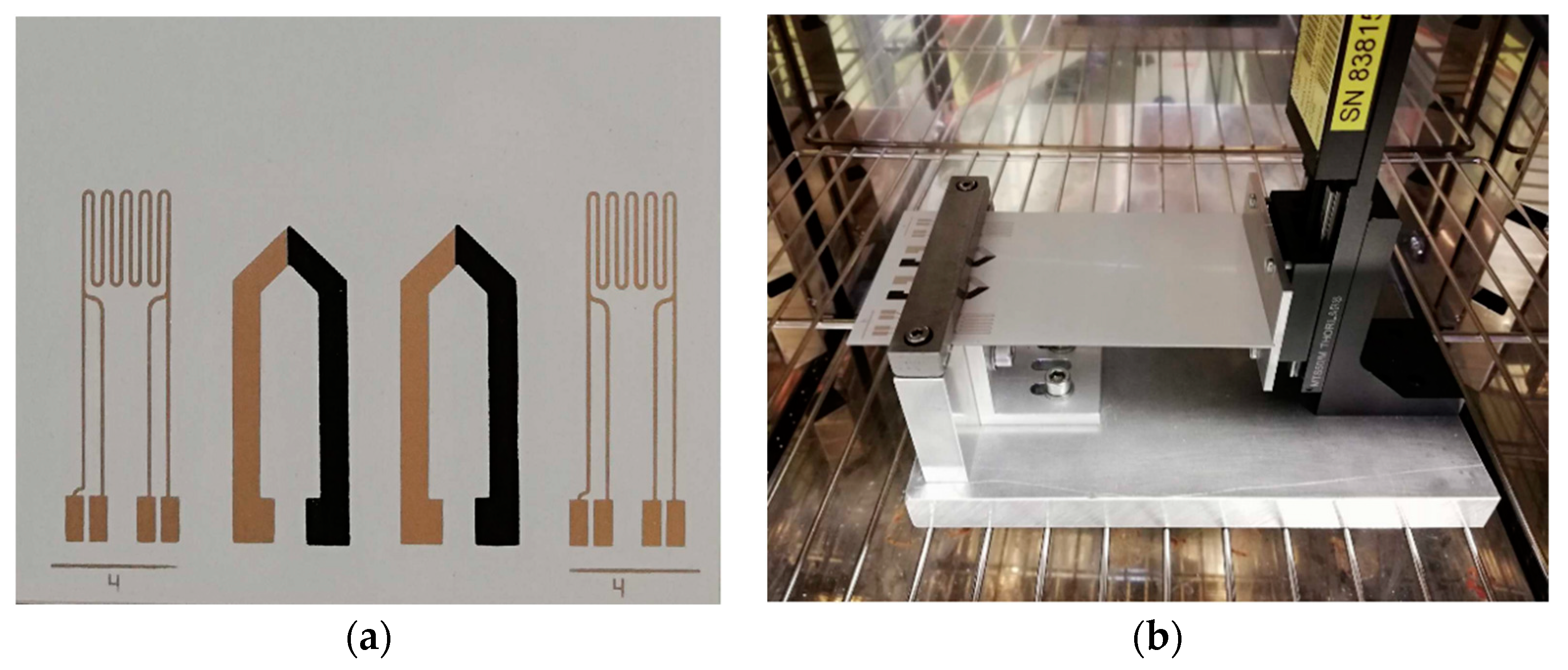
Since the substrate foil is flexible, the thermocouple can also encounter deformations which could potentially affect the output voltage. To investigate if a significant cross-sensitivity between the temperature output and deformation of the thermocouple is present, a deformation test at different temperatures was executed. The thermocouple and a strain gauge were printed onto sheet steel (depicted in Figure 2a), which was subjected to a 5 mm deflection over a length of 100 mm resulting in a strain of 5 × 10⁻⁴ [6]. Due to the thickness of the steel substrate (0.6 mm), a 12 times higher strain could be achieved compared to the thinner PET substrate and due to the Youngs modulus of 200 GPa, a homogeneous deformation over the sample was maintained, thus the steel substrate was used for the bending test instead of the PET substrate. For bending the printed sheet steel was fixed in a clamping device at the one side and at a movable notch on the other side (see Figure 2b). The side with the notch was moved up- and downwards by a motorized stage. To facilitate heating during bending the test setup was placed in a climatic chamber. The setup of the sheet steel and the motorized stage is depicted in Figure 2b.
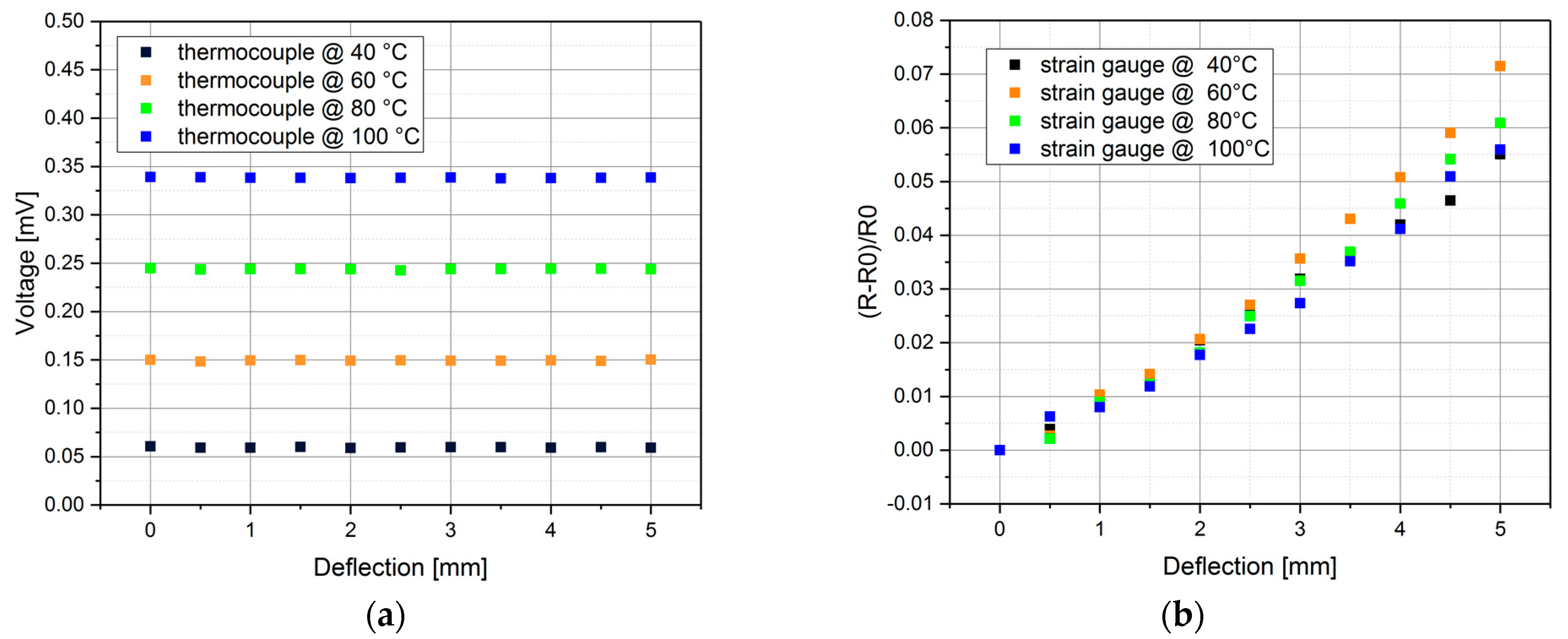
The bending tests were performed at temperatures of 40, 60, 80, and 100 °C, while the thermocouple connections and the strain gauge connections were kept at room temperature. The output of the thermocouple and the strain gauge are depicted in Figure 3a,b. The strain gauge showed an increase in resistance when bent. The thermocouple output voltage only increased with temperature, during bending the output remained constant at constant temperature. Thus, the thermocouples showed virtually no spurious cross-sensitivity of the output voltage to deformation which is essential for measuring the temperature on a flexible substrate.
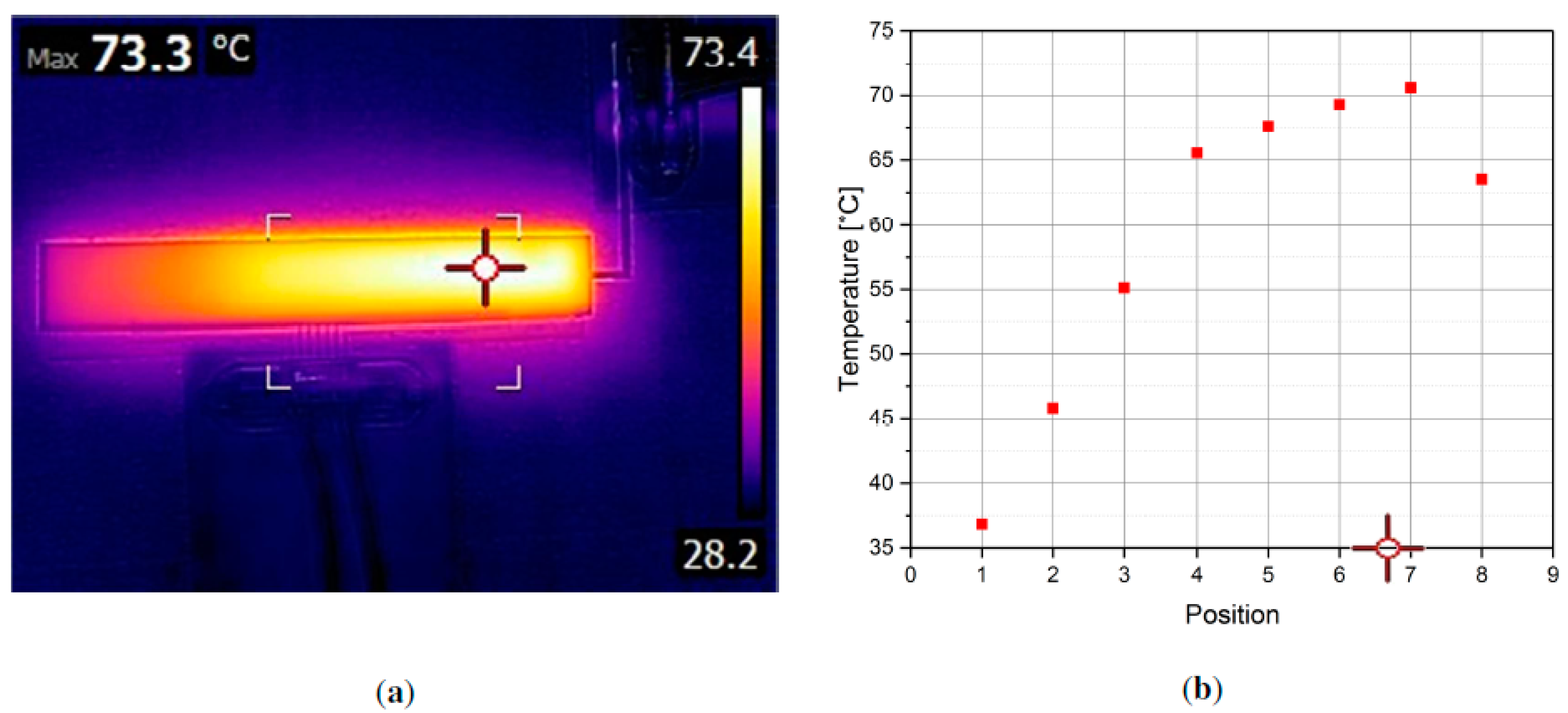
Subsequently, an image of a plastic bar heated on one side was recorded with the fabricated thermocouple-array (Figure 4b), Figure 4a shows the same object recorded with an infrared camera. The red cross in Figure 4a,b marks the highest temperature observed by the infrared camera. The temperature distribution measured with the infrared camera is in accordance with the distribution measured with the thermocouple array.

4. Outlook

Future work will deal with the realization of a thermocouple matrix for condition monitoring to enable a 2D temperature readout of the sample while reducing the amount of connections.

Author Contributions

M.K. fabricated the samples, performed the measurements and wrote the paper, B.M. contributed in the design of the thermocouple readout setup, C.O. helped in the manufacturing process, B.J. and W.H. supervised the work and reviewed the paper. All authors have read and agreed to the published version of the manuscript.

Funding

This work has been supported by the “LCM K2 Center for Symbiotic Mechatronics” within the framework of the Austrian COMET-K2 program.

Conflicts of Interest

The authors declare no conflict of interest. The founding sponsors had no role in the design of the study; in the collection, analyses, or interpretation of data; in the writing of the manuscript, and in the decision to publish the results.

References

  1. Raadnui, S.; Kleesuwan, S. Low-cost condition monitoring sensor for used oil analysis. Wear 2005, 259, 1502–1506. [Google Scholar] [CrossRef]
  2. Zhu, X.; Zhong, C.; Zhe, J. Lubricating oil conditioning sensors for online machine health monitoring—A review. Tribiol. Int. 2017, 109, 473–484. [Google Scholar] [CrossRef]
  3. Yan, R.; Gao, R.X. Complexity as a Measure for Machine Health Evaluation. IEEE Trans. Instrum. Meas. 2004, 53, 1327–1334. [Google Scholar]
  4. Bundy, F.P. Effect of pressure on EMF of thermocouples. J. Appl. Phys. 1961, 32, 483–488. [Google Scholar] [CrossRef]
  5. Singh, R.; Ngo, L.L.; Seng, H.S.; Mok, F.N.C. A silicon piezoresistive pressure sensor. In Proceedings of the 1st IEEE International Workshop on Electronic Design, Test and Applications, Christchurch, New Zealand, 29–31 January 2002; pp. 181–184. [Google Scholar]
  6. Enser, H.; Kulha, P.; Sell, J.K.; Jakoby, B.; Hilber, W.; Strauß, B.; Schatzl-linder, M. Printed strain gauges embedded in organic coatings. Procedia Eng. 2016, 168, 822–825. [Google Scholar] [CrossRef]
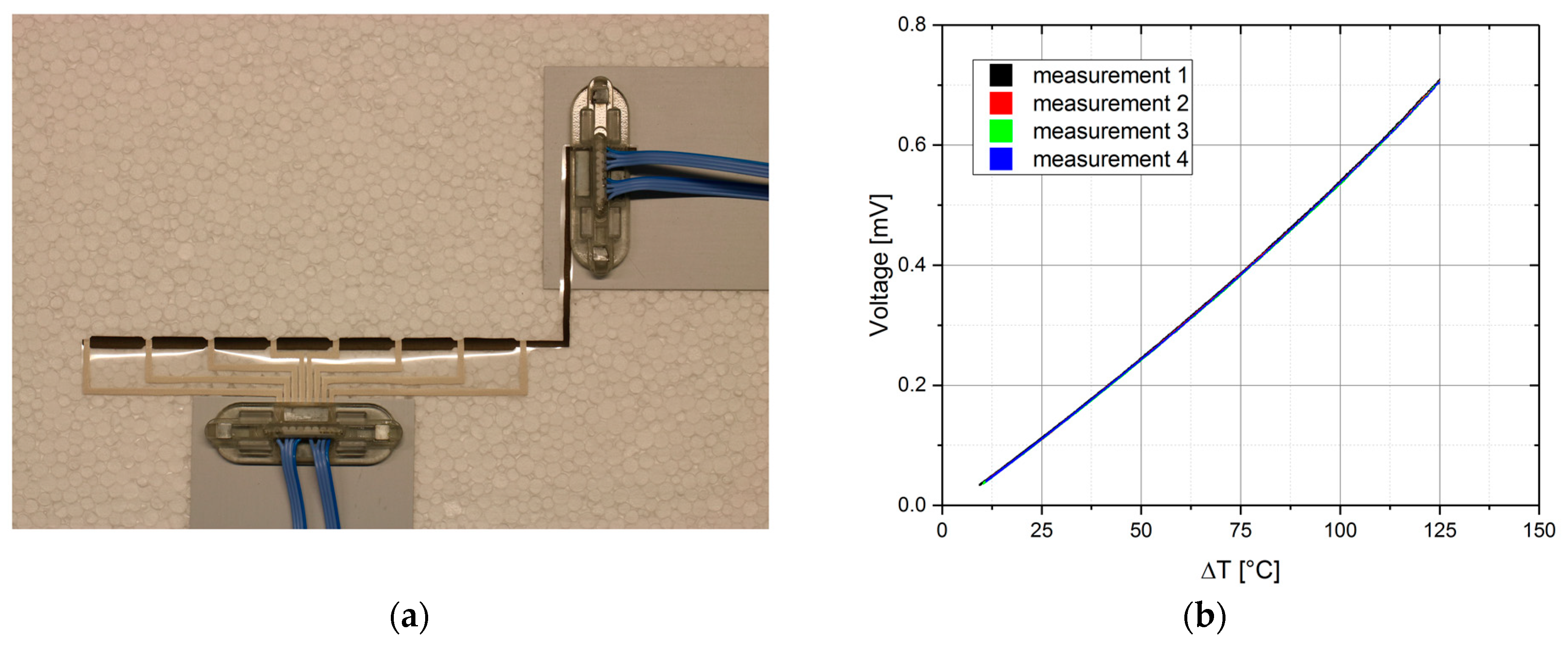
Figure 1. (a) Thermocouple array consisting of one line carbon black which is crossed by eight lines of silver printed on PET-foil; (b) Thermocouple output recorded over four subsequent measurements up to a junction temperature of 150 °C while the terminal was kept at 25 °C resulting in a temperature difference ∆T of 125 °C.
Proceedings 02 00803 g001
Figure 2. (a) Screen printed silver strain gauge with four wire connections and silver carbon black thermocouple printed on insulated sheet steel for bending characterization; (b) Bending test setup consisting of motorized stage and clamping.
Proceedings 02 00803 g002
Figure 3. The sample was placed in a climatic chamber while a motorized stage deflected the substrate (5 mm deflection over 100 mm); (a) Output of the thermocouple for temperatures of 40 up to 100 °C while the substrate was deflected five mm over a length of 100 mm, virtually no sensitivity to deformation can be observed; (b) Change of the strain gauge resistance during deflection of the substrate for temperatures of 40 up to 100 °C.
Proceedings 02 00803 g003
Figure 4. A plastic bar heated on one side was placed on the thermocouple array and the temperature gradient was measured with an infrared camera and the thermocouple array; (a) Thermal image of a heated bar recorded with an infrared camera; (b) Measured temperatures of the bar recorded with the thermocouple array.
Proceedings 02 00803 g004
Publisher’s Note: MDPI stays neutral with regard to jurisdictional claims in published maps and institutional affiliations.