1. Introduction
3D-printing is an effective low-cost technology for demonstrating working principles of newly designed microelectromechanical (MEMS) structures before initiating costly traditional manufacturing technology. Additive manufacturing also compresses product development cycles, favours small-sized manufacturing volumes and, hence, prototyping. Furthermore, it enables the fabrication of ‘true’ three dimensional structures in contrast to bulk and surface micromachining which are limited by their 2D spatial resolution, i.e., a planar process (e.g., deep reactive ion etching; lithography, electroplating and molding technology).
The presented magnetometer combines the advantageous of the resonant operation principle [
1], the optical readout which decouples the sensing part from the electronics components [
2] and a three-dimensional compliant mechanism which proves the potential of additive manufacturing. Literature about additive manufacturing and a study investigating 3D-printed magnetic field sensors can be found in [
3,
4], respectively.
2. Sensing Principle and Fabrication
Figure 1a depicts a 3D-printed micro-mechanical transducer, fabricated with state-of-the-art Multijet Modeling technology [
5]. It features a mechanical conversion of a vertical deflection into a horizontal one. Acrylate as print material was chosen due to its insulating properties, easy accessibility and best possible printing resolution for low-cost rapid prototyping manufacturing. A more detailed description of the working principle of the sensor is illustrated in
Figure 1b. An alternating current applied via the sensing beams yields an oscillation in presence of a static magnetic field. The curved beams transform the out-of-plane deflection into an in-plane movement of the mass by redirecting any perpendicular force into a lateral displacement. Introduced light through the apertures is modulated by relative in-plane movement of the movable mask and second opposite-aligned fixed grating [
2].
3. Measurement Set-Up
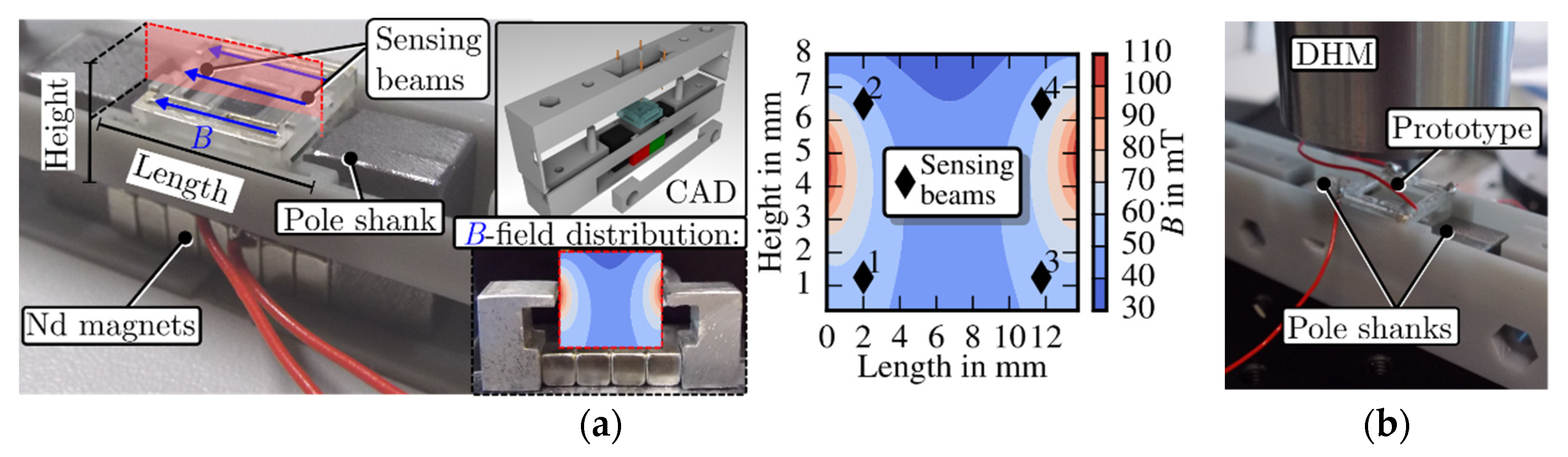
Figure 2a depicts the measurement setup and field distribution which the prototype’s beams experience between two pole shanks, connected with neodymium magnets. The magnetometer was placed within a cavity of a 3D-printed custom made mounting device. Two pole shanks, connected with neodymium magnets introduced a horizontal magnetic field. Nevertheless, geometry and rather large distance of the pole shanks yields a diverging field distribution which was characterised with a Hall probe. The approximate field strength which the beams experience was obtained from that measurement. An LED and four spring probe pins were integrated at the top part of the mounting device, whereas a photodetector was placed below the prototype and magnets at the bottom part. A Keithley current source model 6221 provided an alternating current via the spring probe pins to the prototype’s beams and, hence, induced out-of-plane deflection. These oscillations were converted into an in-plane movement of the mass by the curved beams, thus enabling light flux modulation. This modulated light was detected by a photodiode, the output signal amplified with a transimpedance amplifier and acquired with a lock-in amplifier (SR830).
In the second measurement setup, the lateral displacement of the mass was quantified with a digital holographic microscope (
Figure 2b). Therefore, the top part of the mounting device was removed to access the transducer.
4. Simulation & Measurement Results
The prototype’s complex geometry was investigated in three different ways. First, an FEM analysis was accomplished with COMSOL Multiphysics to reveal the trancducer’s eigenfrequencies and study its behaviour within a static magnetic field. Secondly, the sensor’s transfer function was measured with the optoelectronics, i.e., optical readout consisting of photodiode and LED. Lastly, the displacement of the mass was measured via the DHM.
Figure 3 depicts simulation results of the prototype’s eigenfrequencies, where the desired frequency occurs at 706.8 Hz (
f2). The mode at
f1, which forces an out-of-plane deflection of the mass, will not contribute to the light flux modulation, thus is neglectable. On the other hand, the rotational mode at
f3 affects the modulation principle, depending on the magnetic field direction, as we will discuss in the measurement results and more in-depth simulations.
The structure’s vibration behaviour was investigated in two simulation settings in a frequency range of 500–1000 Hz.
Figure 4a depicts an approximately simulated field distribution equivalent to the magnetic field occurring between the pole shanks. A frequency domain simulation was conducted by applying an alternating current via the cantilevers within this field setting yielding a transfer function with two distinctive peaks shown in
Figure 4b (Sim. equiv.). The second simulated transfer function (Sim. ideal) originates from a true homogeneous magnetic field pointing horizontally to the structure’s cantilever. Note that the peak at
f3 is almost negligible compared to the former simulation result. The transfer functions ‘PD measr.’ and ‘DHM, inplane’ in
Figure 4b were obtained from the measurement with the optoelectronics and the digital holographic microscope, respectively. The prototype was excited with 20 mA alternating current during both measurements. The measurement confirms the simulation results. The rotational mode (
f3) is superimposed with an in-plane oscillation and thus appears more pronounced within a heterogeneous magnetic field. This enables a detectable modulated light flux with the optoelectronics and in-plane displacement measurements with the DHM. The equivalent simulated and measured transfer function exhibit a similar shape but differ in frequency of the observed modes.
5. Conclusions
Complex geometry, fast design and testing phases are feasible with 3D-print technologies in contrast to costly re-design and fabrication cycles in traditional MEMS fabrication. A 3D-printed magnetometer featuring a compliant mechanism was manufactured and investigated. The measurement and simulation results of the structure within a heterogeneous magnetic field imply a superimposed in-plane and out-of-plane deflection of the mass. However, a pure in-plane oscillation of the mass occurs according to the simulation result of the prototype in an idealised environment with a perfectly horizontally applied homogeneous field. In other words, with a true homogeneous field present the compliant mechanism fully converts the cantilevers’ out-of-plane oscillations into in-plane deflection of the mass. Furthermore, the observed frequency shifts might be caused by the clamping mechanism of the mounting device. Spring probe pins fixes the prototype from the top and introduce tension during the measurement with the optoelectronics, whereas the structure is more relaxed during the displacement measurement (DHM), as the top part of the mounting device is removed.

 ,
, 