Proceeding Paper

Novel 3D-Printed MEMS Magnetometer with Optical Detection †

1
Department for Integrated Sensor Systems, Danube University Krems, 2700 Wiener Neustadt, Austria
2
Institute of Sensor and Actuator Systems, TU Wien, 1040 Vienna, Austria
*
Author to whom correspondence should be addressed.
Presented at the Eurosensors 2018 Conference, Graz, Austria, 9–12 September 2018.
Proceedings 2018, 2(13), 783; https://doi.org/10.3390/proceedings2130783
Published: 23 November 2018
(This article belongs to the Proceedings of EUROSENSORS 2018)

Abstract

:
This paper reports a novel 3D printed MEMS magnetometer with optical readout, which demonstrates the advantages of 3D printing technology in terms of rapid prototyping. Low-cost and fast product development cycles favour 3D printing as an effective tool. Sensitivity measurement with such devices indicate high accuracy and good structural performance, considering material and technological uncertainties. This paper is focusing on the novelty of the rapid, 3D-printing prototyping approach and verification of the working principle for printed MEMS magnetometers.

1. Introduction

Additive manufacturing technologies for micromachining MEMS devices are emerging, favouring small-sized manufacturing volumes and prototyping purposes. These technologies comprises inkjet deposition, laser-, ion-, electron beam and scanning probes to add or remove material. Fast design and testing phases are feasible with 3D-printing technologies compared to costly re-design and fabrication cycles in traditional MEMS fabrication processes. A study about the options for additive rapid prototyping methods can be found in [1,2]. Low-cost 3D-printing technologies have also their potential in education for MEMS design and fabrication, where students experience the challenge of iterative modelling and design processes on upscaled MEMS devices [3].
The presented magnetometer benefits from the resonant operation principle [4], i.e., magnitude amplification and the advantage of the optical readout which has proven to be highly sensitive [5,6]. Recently, a silicon Lorentz force based transducer for magnetic field detection was demonstrated in [7]. However, this work emphasise the advantages of 3D print technologies in terms of fast design and accelerated testing phases. Reference [8] offers a more profound study about 3D printed magnetic field sensors.

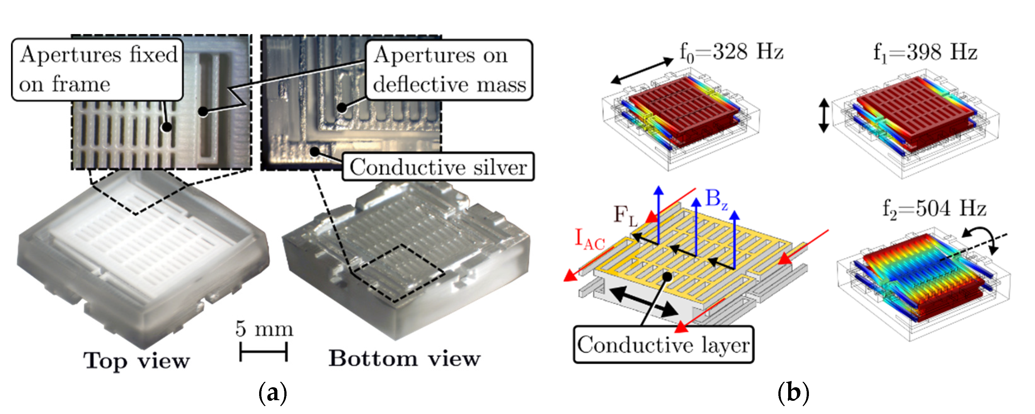
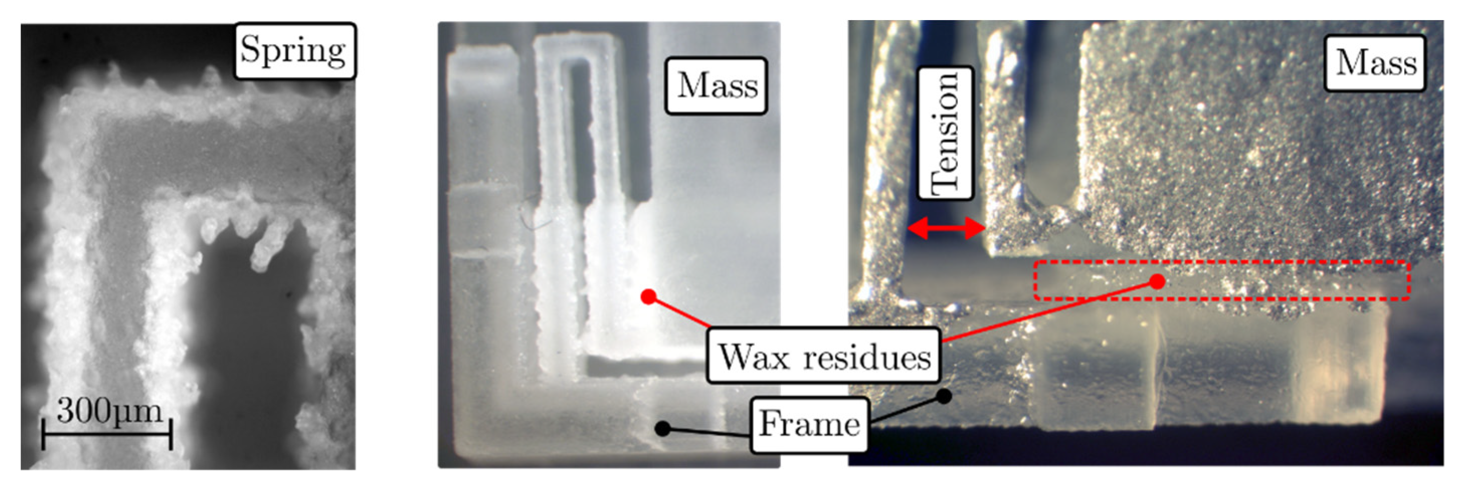
2. Sensing Principle and Fabrication

The prototype, depicted in Figure 1a, is printed from a photo-reactive acrylate resin with state-of-the-art 3D printing Multijet Modeling (MJM) technology. Acrylate as print material features the best possible printing resolution on the market for low-cost manufacturing, insulating characteristics and easy accessibility. A deflectable mass designed with apertures, coated with conductive silver, and suspended by eight springs attached to a frame is shown. The corresponding grating is aligned on the opposite side and fixed to the structure’s stationary frame. Applying an alternating current on top of the deflectable structure yields an oscillation in presence of a static magnetic field and, hence, modulates an introduced light flux by relative in-plane movement of mass and stationary mask.
The Lorentz force principle and finite element method (FEM) simulation results of the prototype’s eigenmodes is depicted in Figure 1b. Properties of acrylic plastic such as the material density of 1200 kg/m3 and Young’s modulus of 1420 MPa were selected for the simulation.
The MJM printing process simultaneously dispenses and cures a photopolymer through a printing head in a layer-by-layer process with achievable resolutions of 16 µm [1]. Nevertheless, the structural design is restricted by the manufacturer to guarantee handling and cleaning of the prototypes. Most manufacturers recommend a minimum thickness of 0.3 mm for walls and 0.6 mm for free standing areas to prohibit agglutination or buckling. Further, a wax-like material supports the printing process, i.e., cavities and free standing areas, that must be removed in an ultrasonic bath after printing. Figure 2 depicts such wax residues on a poorly designed prototype.

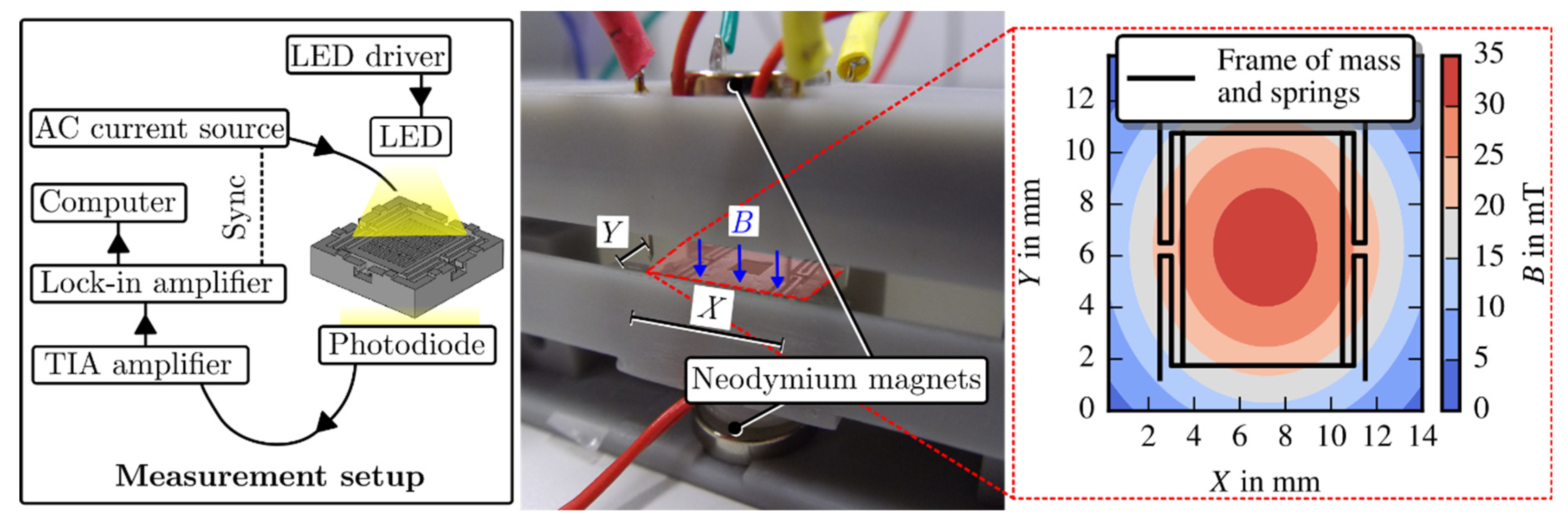
3. Measurement Set-Up
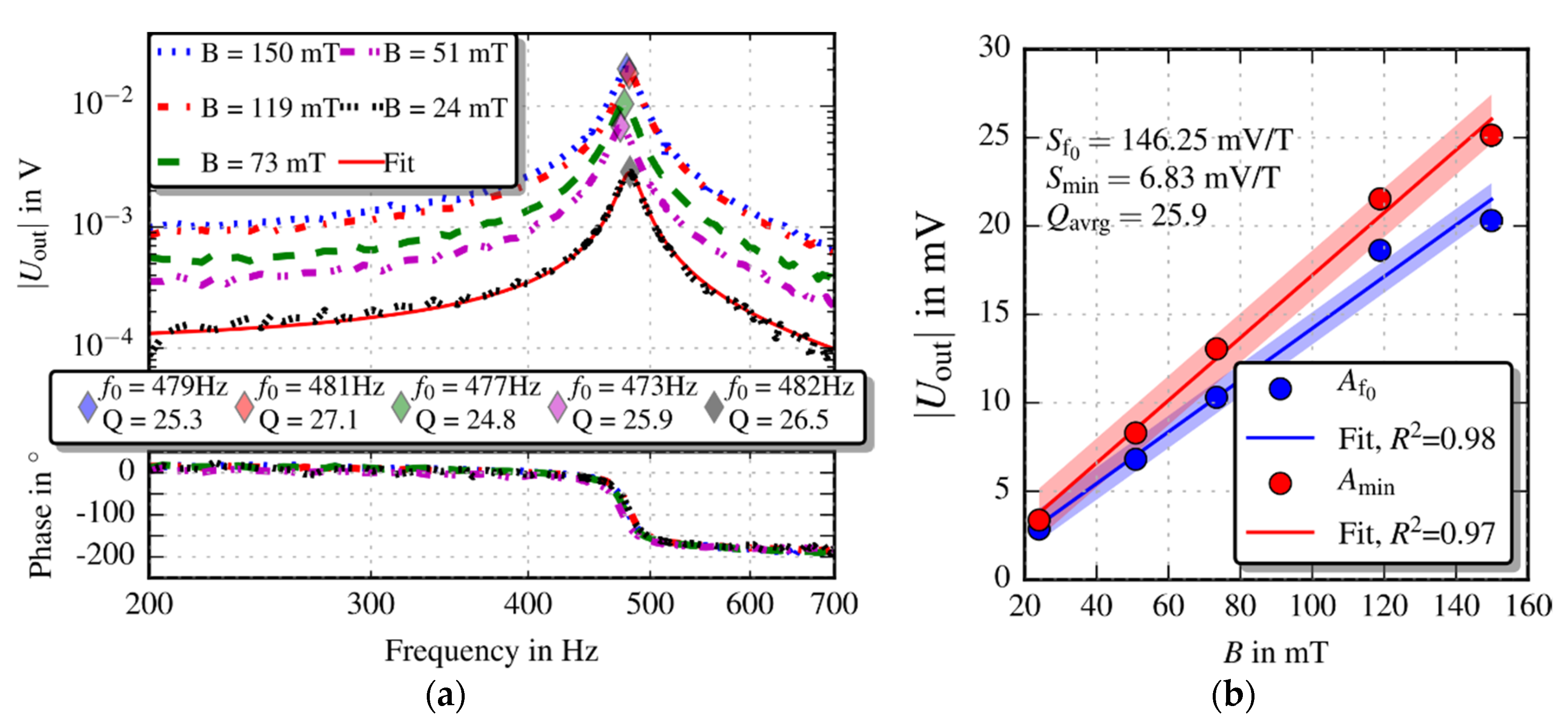
Figure 3 depicts the experimental setting for the characterisation of the prototype’s responsitivity. A custom made mounting device, also 3D printed, consists of four spring probe pins which clamps the prototype into a cavity and additionally feeds the excitation current. Spaces for neodymium disc magnets in the top and bottom part of the device allows easy replacement of the magnets. An LED and photodiode is integrated in the top and bottom part of mounting device, respectively. The detected modulated light flux is amplified using a trans-impedance amplifier (TIA, OPA404) and acquired with a lock-in amplifier (Stanford Research Systems SR830) resulting in magnitude and phase data of the overall sensor transfer function. The field distribution depicted on the right in Figure 3 was measured with a transversal Hall effect sensor (AS-NTM-2, Teslameter, Project Elektronik, Berlin, Germany ).

4. Results

The responsitivity of the magnetometer is measured at the structure’s natural frequency f0 by applying a set of magnetic field strengths and, thus, demonstrating a linear behaviour of the output signal. The applied excitation current was set to 20 mA (peak-peak) during the measurements. Figure 4a depicts the measured transfer functions for five different magnetic field strengths. An averaged quality factor Qavrg of 25.98 and averaged natural frequency f0 of 478.38 Hz have been extracted from the fitting curves. Tension through the clamping mechanism, introduced by the spring probe pins, causes a variation in frequency and, consequently quality factor.
The prototype’s linear behaviour depending on the magnetic field strength is shown in Figure 4b. The responsitivities Sf0 = 146.25 mV/T and Smin = 6.83 mV/T were extracted at resonance and at 200 Hz, respectively. Further, the data set of Smin is harmonised, hence multiplied with Qavrg to allow comparison with the data at resonance in Figure 4b. In theory, Sf0 and the harmonised responsitivity Smin,harm = 177 mV/T should be the same. Nevertheless, the values differ due to possible non-linearity effects, multiplication of Smin with the averaged quality factor, influence of noise and a chosen low frequency range (200 Hz) which is too close to the prototype’s resonant frequency (frequency ratio fmin/f0 = 0.42). The latter argument must be considered as more decisive but resolvable by reducing the frequency ratio.
Furthermore, the prototype’s stiffness was estimated to be k = 36 N/m by taking its averaged resonance frequency and the approximate mass of the deflectable part from the CAD drawing (≈158 mg).

5. Conclusions

A Lorentz force based magnetometer was 3D printed with state-of-the-art technology and characterised. The prototype’s behaviour in a static magnetic field was studied, revealing a responsitivity of 146 mV/T. However, 3D printed MEMS resonators are currently limited in terms of achievable printing resolutions and mechanical properties of polymer materials, i.e., the tensile modulus of silicon is approximately two orders of magnitude larger than the one of polyacrylates or polycarbonates. Nevertheless, the ongoing development on the 3D printing market promises enhancements in printing resolution and accuracy, as well as developing new printable composite materials which offer a wider range of mechanical properties.
The results proof that rapid prototyping is a useful and effective assessment tool to demonstrate working principles for designs before initiating costly conventional MEMS technology.

Acknowledgments

This work was supported by the country of Lower Austria, the Austrian Science Fund (FWF, project P 28404-NBL) and the prototype funding program PRIZE (project P1621687) of the Austria Wirtschaftsservice Gesellschaft mbH (aws).

Conflicts of Interest

The authors declare no conflict of interest.

References

  1. Lifton, V.A.; Lifton, G.; Simon, S. Options for additive rapid prototyping methods (3D printing) in MEMS technology. Rapid Prototyp. J. 2014, 20, 403–412. [Google Scholar] [CrossRef]
  2. Fischer, A.C.; Mäntysalo, M.; Niklaus, F. Chapter 26—Inkjet Printing, Laser-Based Micromachining and Micro 3D Printing Technologies for MEMS. In Handbook of Silicon Based MEMS Materials and Technologies, 2nd ed.; William Andrew Publishing: Norwich, NY, USA, 2015; pp. 550–564. [Google Scholar] [CrossRef]
  3. Dahle, R.; Rasel, R. 3D Printing as an Effective Educational Tool for MEMS Design and Fabrication. IEEE Trans. Educ. 2016, 59, 210–215. [Google Scholar] [CrossRef]
  4. Herrera-May, A.; Soler-Balcazar, J.; Vázquez-Leal, H.; Martínez-Castillo, J.; Vigueras-Zuñiga, M.; Aguilera-Cortés, L. Recent Advances of MEMS Resonators for Lorentz Force Based Magnetic Field Sensors: Design, Applications and Challenges. Sensors 2016, 16, 1359. [Google Scholar] [CrossRef] [PubMed]
  5. Hortschitz, W.; Steiner, H.; Sachse, M.; Stifter, M.; Kohl, F.; Schalko, J.; Jachimowicz, A.; Keplinger, F.; Sauter, T. Robust Precision Position Detection with an Optical MEMS Hybrid Device. IEEE Trans. Ind. Electron. 2012, 59, 4855–4862. [Google Scholar] [CrossRef]
  6. Hortschitz, W.; Steiner, H.; Stifter, M.; Kohl, F.; Kahr, M.; Kainz, A.; Raffelsberger, T.; Keplinger, F. Novel high resolution MOEMS inclination sensor. In Proceedings of the 2014 IEEE Sensors, Valencia, Spain, 2–5 November 2014; pp. 1893–1896. [Google Scholar] [CrossRef]
  7. Hortschitz, W.; Steiner, H.; Stifter, M.; Kainz, A.; Kohl, F.; Siedler, C.; Schalko, J.; Keplinger, F. Novel MOEMS Lorentz Force Transducer for Magnetic Fields. Procedia Eng. 2016, 168, 680–683. [Google Scholar] [CrossRef]
  8. Kahr, M. Design and Characterisation of 3D-Printed Magnetic Field Sensors. Master’s Thesis, TU Wien, Vienna, Austria, 2017. Available online: http://katalog.ub.tuwien.ac.at/AC14477184 (accessed on 1 April 2018).
Figure 1. (a) 3D-printed magnetometer designed with 32 apertures with a particular size of 400 × 2000 µm and coated with conductive silver. (b) Schematic representation of the Lorentz force principle and FEM simulation results of the first three eigenmodes.
Proceedings 02 00783 g001
Figure 2. Limitation of 3D printing technology is shown by the very first prototype. Surface roughness occurs at long and thin free standing areas, e.g., springs (left). Remaining wax and acrylate residues introduce clumping (middle) and tension (right).
Proceedings 02 00783 g002
Figure 3. Schematic configuration of the measurement setup on the left. The image in the middle depicts a prototype arranged in between two neodymium disc magnets and partly opened mounting device. The red area indicates the associated distribution of the magnetic flux density, characterised with a Hall effect sensor.
Proceedings 02 00783 g003
Figure 4. Measured transfer functions (a) and measured output signal versus magnetic flux density with linear fit (b). All data were fitted to extract the quality value Q via the −3 dB bandwidth method and f0. A f0 and Amin are the measured values at the structure’s resonance frequency and at 200 Hz, respectively. Amin was harmonised, hence multiplied with the averaged quality factor Qavrg, to allow comparison with the data at resonance.
Proceedings 02 00783 g004
Publisher’s Note: MDPI stays neutral with regard to jurisdictional claims in published maps and institutional affiliations.

