1. Introduction
In our everyday life, there is a substantial number of unexploited thermal gradients that could be used for energy harvesting by thermoelectric means. However, the most abundant thermal gradients are small and do not allow the inclusion of efficient heatsinks, which makes the conventional TEGs unsuitable for such low-energy-density applications. A new thin-film TEG design applicable for large-area, heatsink-limited applications has previously been proposed and the performance analyzed computationally [
1,
2]. With such designs, the heat leakage through the module itself can be minimized and the available temperature gradient maximized.
Another major barrier for a wider use of thermoelectric devices for energy harvesting is their low efficiency, which tends lead to a high cost per converted power. The ability to use non-toxic and abundant materials has also become increasingly important in the recent years and enhanced the interest towards improving the thermoelectric properties of metal oxides. Tin-doped indium oxide (ITO) is one of the most commonly used transparent conductive oxides due to its high electrical conductivity and high transparency. However, aluminum-doped zinc oxide (AZO) provides an environmentally friendly alternative that is more abundant, has better thermoelectric properties and lower cost.
In this paper, we combine the thin-film TEG approach designed for large-area, heatsink-limited applications with the environmentally friendly abundant thermoelectric (TE) material, AZO.
2. Materials and Methods
Yellow polyimide (Kapton NH
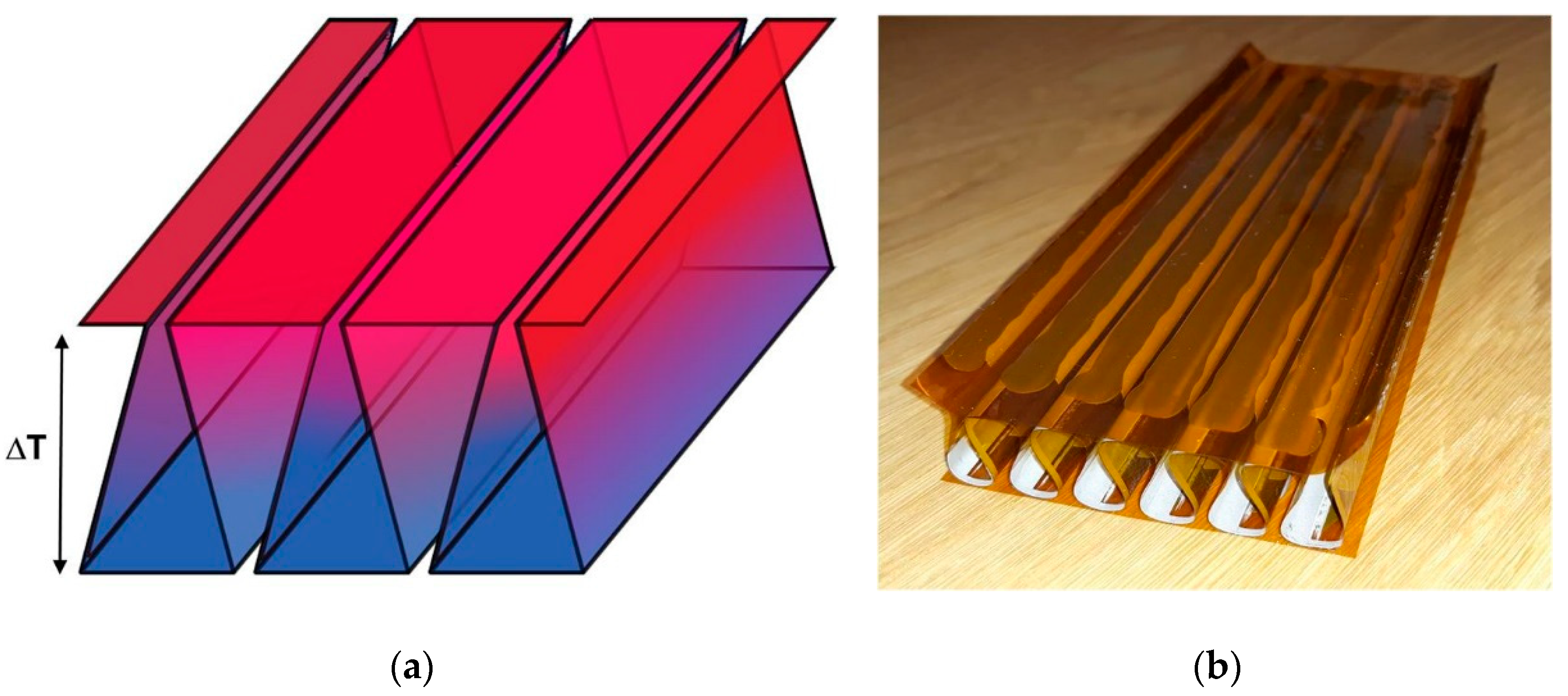
®) films of 25 μm in thickness were used as substrates for the AZO coating. To enable sufficiently low process temperatures required by the flexible substrates, atomic layer deposition (ALD) performed by Picosun was used to coat the substrates with AZO. Silver ink electrodes (Inkron IPC-114) were coated on AZO by screen printing and the TEG legs defined by sanding AZO away between the adjacent electrodes at the same temperature so that the planar thin-film TE elements are connected electrically in series on the substrate. After the appropriate folding of the substrate, the three dimensional (3D) TE module is formed with the TE elements connected thermally in parallel as shown in
Figure 1.
The structure was simulated with Comsol
® Multiphysics, using the parameter values listed in
Table 1. Additionally to these values, the total resistance of eleven TEG elements connected in series was measured to be 100 Ω. The contact resistance of 30 Ωcm
2 between AZO and the silver conductor was extracted from the simulations.
The module prototype was measured by placing it on a heat plate and cooling it down from above using ice. An aluminum plate with pt-100 temperature sensors was placed between the module and the bag of ice to even up and measure the temperature of the cold side. In the measurement, the module was loaded with different resistance values and the voltage produced by the module was recorded as a function of the resistance, based on which the DC power can be calculated.
3. Results
Here, we present the first experimental results of the new TEG design supported by theoretical calculations. The basic structure of the TEG is fabricated on flexible foils, which allows low-cost processing methods and makes the devices suitable for large-area applications. The TEG foil is folded in such a way that both the heat flux and current flow are parallel to the thermoelectric thin-film but the temperature gradient is perpendicular to the plane of the thermoelectric module, as indicated in
Figure 1a. It is shown that the latter minimizes the heat leakage through the module itself and maximizes the available temperature gradient under heatsink-limited conditions.
In
Figure 2, the simulated temperature gradient (Δ
T) available for power production is depicted as a function of the thickness of the thermoelectric module prepared of different materials. It can be seen that the heat leakage through the folded module itself is very small compared to the conventional bulk or thin-film TEGs where the heat and electrical current are flowing across the plane of the TE films, and that the behavior of the folded TEG is very close to that of air. Under heat sink limited conditions with only free convection available for heat transfer on the cold side of the TEG, the conventional TEGs can support only a fraction of the temperature gradient sustained by the folded TEG.
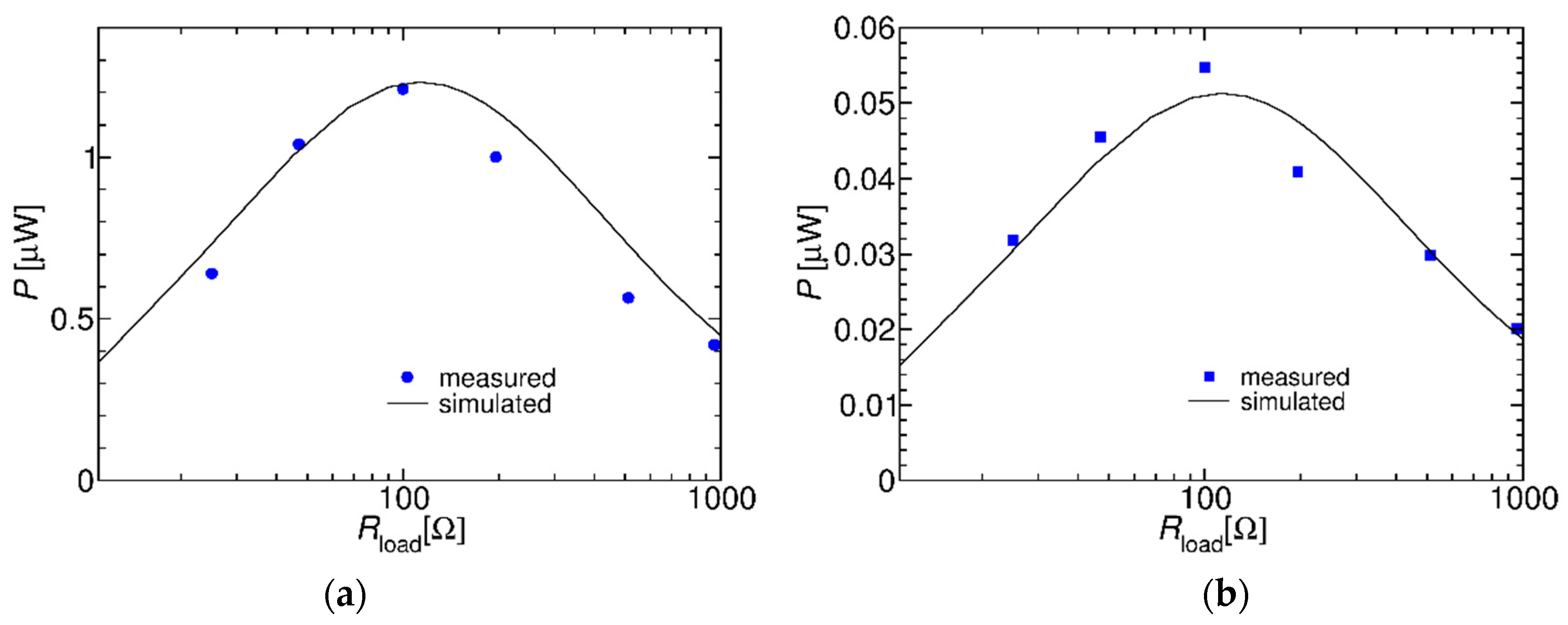
The fabricated TEG module of 11 elements (145 mm × 60 mm in size) connected in series was measured to produce 1.2 µW of power for a temperature gradient of 49 K (
Figure 3). For a temperature gradient of 10 K, more commonly available in building applications, such devices are able to produce 6.3 µW for a 1 m
2 window. The maximum power is measured at the resistance value of 100 Ohms, which is also the measured series resistance of the TEG module.
4. Discussion
A new concept of a thermoelectric generator based on a transparent AZO layer on a flexible foil has been proposed and demonstrated. When compared to traditional TEGs, the proposed solution is light-weight and the heat conduction through the structure is minimal, i.e., close to that of air. TEGs generally operate most efficiently with large temperature differences, which can be seen also by the difference between
Figure 3a,b. Therefore, also this particular solution may appear most useful in environments where large temperature differences are present, e.g., in airplanes that would also benefit from the light weight.
Author Contributions
K.T. and K.J. conceived and designed the experiments; K.J. performed the experiments; K.T. performed the simulations; K.T. and K.J. analyzed the data; K.T. and K.J. contributed analysis tools; K.T. and K.J. wrote the paper.
Acknowledgments
This project has received funding from the European Union’s Horizon 2020 research and innovation programme 2014–2018 under grant agreement No 645241. The partial funding from VTT Technical Research Centre of Finland Ltd. is also gratefully acknowledged. The authors would like to thank R. Ritasalo from Picosun for providing the AZO coating by ALD process for the TEGs. The authors would also like to thank their colleagues at VTT: M. Hillukkala, M. Korkalainen, I. Marttila and T. Pernu for the development of the electronics of the sensor node, and R. Grenman and M. Vilkman for screen printing the silver conductors on the TEG foils.
Conflicts of Interest
The authors declare no conflict of interest. The founding sponsors had no role in the design of the study; in the collection, analyses, or interpretation of data; in the writing of the manuscript, and in the decision to publish the results.
References
- Tappura, K. A numerical study on the design trade-offs of a thin-film thermoelectric generator for large-area applications. Renew. Energy 2018, 120, 78–87. [Google Scholar] [CrossRef]
- Jaakkola, K.; Tappura, K. Exploitation of Transparent Conductive Oxides in the Implementation of a Window-Integrated Wireless Sensor Node. IEEE Sens. J. 2018, 18, 7193–7202. [Google Scholar] [CrossRef]
| Publisher’s Note: MDPI stays neutral with regard to jurisdictional claims in published maps and institutional affiliations. |
© 2018 by the authors. Licensee MDPI, Basel, Switzerland. This article is an open access article distributed under the terms and conditions of the Creative Commons Attribution (CC BY) license (https://creativecommons.org/licenses/by/4.0/).


