Abstract
An electrostatic membrane actuator with an elastomer membrane as movable part and silver nanowires (AgNWs) as flexible electrode material is built and characterized. A layered and modular actuator design facilitates simple and fast modification of actuator properties for characterization purposes. The tested actuators allow a membrane center deflection in the range of over 50 μm with applied voltages lower than 1 kV. The observable membrane center deflection exhibits a viscoelastic creep behavior. With the aim to achieve a more stable membrane deflection, a simple correction function was applied to the constant electrode voltage thus compensating the linear creep rate. With this method, the creep rate was changed from +0.27 μm/s to −0.08 μm/s. This method already improves the stability of the actuator deflection to a high degree.
1. Introduction
Electrostatic actuators with AgNWs as electrode material have been demonstrated in the past. The reported applications include switchable transmission windows [1], tactile surfaces [2] and tunable optical lenses [3]. These actuator systems are operated with voltages above 1 kV while still providing an actuation travel below 200 μm. To reduce the required voltage, an actuator was designed and built within this study which can achieve similar membrane deflection with voltages below 1 kV.
The actuator is designed in a modular manner to provide for a simple variation of the dominating actuator properties. The different layers of this actuator and their dimensions are shown in Figure 1. To form the electrostatic actuator, all layers are stacked and held in place by a milled PMMA casing not shown in the sketch. The membrane center deflection is monitored with a laser displacement sensor mounted above the center of the movable PDMS membrane.
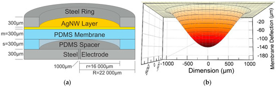
Figure 1.
(a) Schematic cut of the actuator model showing the individual layers. (b) Simulation of the membrane deflection with the dimensions of the model introduced in (a) at an applied voltage of 700 V.
2. Materials and Methods
The actuator design is different to the usually reported Dielectric Elastomer Actuators (DEAs). The actuation of DEAs is realized by compressing an elastomer membrane within two electrode layers, to cause a lateral deformation of the membrane material. Here, an elastomer membrane is deformed into an air-filled cavity by the Maxwell force caused by the electric field applied to the electrodes. The discussed actuator setup is fabricated in a modular way and can be modelled with a method based on Kirchhoff’s plate equation.
2.1. Actuator Fabrication
The membrane actuator is designed in a layered modular way facilitating an easy exchange of individual layers to vary the actuator dimensions. A schematic cross section of such an actuator is depicted in Figure 1a. The bottom layer of the actuator is formed by a steel electrode with a thickness of 300 μm and a diameter of 22 mm. To avoid an influence on the membrane deformation by compressing the air inside the cavity, a 1 mm hole is located at the center of the steel plate. An elastomer spacer ring is placed on top with an inner and outer diameter of 16 mm and 22 mm, respectively, and a height of 300 μm. The 300 μm thick elastomer membrane is located on top of the spacer ring. The upper membrane surface is covered with silver nanowires to provide a flexible and electrically conductive electrode layer. This layer is contacted by a steel ring electrode having the same lateral dimensions as the spacer ring and a thickness of 300 μm.
To manufacture the elastomer components, a polydimethylsiloxane (PDMS) (Sylgard® 184 Silicone Elastomer, Dow Corning, Midland, MI, USA) film was casted in a milled PMMA mold with a depth of 300 µm. The circular shape of the membrane and spacer ring were punched out of the cured PDMS film. The steel electrodes were laser cut from a steel foil (h+s Präzisionsfolien GmbH, Pirk, Germany) using a nanosecond pulsed Nd:YAG-Laser (DPL Smart Marker II, ACI Laser GmbH, Nohra, Germany).
The nanowires were synthesized in a polyol process reported by Korte et al. [4] that was modified as described in an earlier publication [5]. For improving the wettability of the PDMS surface, the membranes were treated with oxygen plasma for one minute before applying an ethanol solution containing nanowires by drop casting, until a closed layer was formed. After that, the membrane was left at room temperature for evaporation of the ethanol solution, thus producing a web of nanowires on the PDMS membrane. To increase the contact area between the individual nanowires and therefore the layer conductivity, the nanowire covered membranes were heated to 150 °C in a convection oven for 30 min. This process is necessary to weld the nanowires together at their contact points and melt away their side passivation polymer (polyvinylpyrrolidone) remaining from the synthesis process. Otherwise, this layer would electrically insulate the nanowires from each other and prevent the formation of an electrically conductive layer.
2.2. Actuator Model
Based on Kirchhoff’s plate equation, a model for the prediction of the membrane deformation was established. With the approximation of the actuator as a parallel plate capacitor the resulting force was assumed to be constant, even under actuation deformation. The dependency of the membrane center deflection on the voltage w(U) and the actuator dimensions is given by
w(U) = C·U2 r4 [m3 (m + s)·(m·εc + s·εm)]−1.
Here, m and s are the thickness of the membrane and spacer, respectively, r the inner radius of the spacer defining the membrane area, εc and εm the dielectric permittivities of air between the plates and the membrane material, respectively, U the voltage applied to the electrodes and C a constant containing further constant material parameters. Figure 1b shows a deflected membrane with this model at a state when 700 V are applied to the actuator electrodes.
2.3. Measurement
The actuator described in Section 2.1. is mounted into a PMMA casing. A laser distance sensor (LK-G32, Keyence, Neu-Isenburg, Germany) is used for measuring the membrane displacement when a voltage is applied to the electrodes by a high voltage supply (SVR 353-3bip, Piezomechanik GmbH, Munich, Germany). The displacement is recorded over time with a sample rate of 1 kHz. Measurements of the membrane deflection over the time with constant voltages applied show a viscoelastic creep behavior, as can be seen in Figure 2a. The viscoelastic creep varies with the applied voltages, as listed in the legend of Figure 2a.

Figure 2.
(a) Recorded membrane deflection behavior with various constant voltages applied. The linear creep rate b for the shown cases is listed above each dataset. (b) The creep compensation with an applied voltage of 700 V (b). The applied constant (black) and corrected voltage (yellow) are also included.
3. Results
A measurement of the actuator deformation was performed by applying different voltages to the electrodes and monitoring the membrane deformation over time. Measurement results are shown in Figure 2a. A viscoelastic creep behavior can be observed after the immediate deflection happening instantaneously after the application of voltage. This creep behavior can be divided into two regimes, the first one being dominated by a behavior decaying exponentially in time and the second one showing a linear behavior in time. This time-dependent deflection wcreep(t, U0) can be described with the equation
wcreep(t, U0) = w0(U0) + b·t + c·exp(−t/d).
The instantaneous membrane deflection w0(U0) results from the applied constant voltage U0, b is the linear creep constant and the third term the exponential creep onset with the amplitude c and the time constant d. In general, this viscoelastic creep is disadvantageous for applications that require a constant state of deformation. While the exponentially decaying part may be compensated by simply re-adjusting the actuation voltage, the linear long-term drift is highly subjective to the actual actuation time and has therefore to be compensated by a time-variable approach.
Linear Creep Compensation
In a first approach, that is shown here, a compensation of only the more relevant, linear part of the creep was performed by neglecting the exponential term in Equation (2) resulting in
wcreep(t, U0) = w0(U0) + b·t.
Using Equation (1) and including all material properties and actuator dimensions in a constant α, a corrected function for the applied voltage in time can be obtained:
U(t) = α·(w0(U0) − b·t)1/2.
The linear creep rate is subtracted from the displacement caused by the initially constant voltage to compensate for the creeping deformation. The creep constant b is determined in this case as the slope of a linear regression to the data of the measurement interval from t = 6 s to t = 31 s. The compensation of the linear creep is demonstrated with an applied constant voltage of 700 V (black) in Figure 2b. The linear creep rate in the measurement (red) is determined to +0.27 μm/s in the before mentioned interval. The applied voltage following the compensation function of Equation (4) is also shown in Figure 2b (yellow) as well as the resulting membrane deflection (blue). The slope of the resulting creep-compensated measurement is −0.08 μm/s, being a threefold reduction of the absolute deflection variation over time.
4. Conclusions
The described, rather simple model provides a fast and easy method to compensate for the viscoelastic creep of an electrostatically deflected PDMS membrane. The initial linear creep of +0.27 μm/s, observed when applying a constant voltage of 700 V to the actuator, was changed to −0.08 μm/s by applying a voltage correction function. This results in a threefold decrease of the absolute viscoelastic creep and stabilizing the membrane deflection enabling a further characterization of the deformed membrane. Improving the model boundary conditions and including the neglected exponential onset of the viscoelastic creep may reduce the slight overcompensation leading to a more stable membrane deflection.
Author Contributions
The actuator fabrication, data acquisition and processing were performed by N.S. in the scope of a Bachelor Thesis. S.S. conceived and designed the experiments, analyzed the data and wrote the paper. F.G. proposed the research project and was involved in the interpretation of the results. The research was conducted in the Laboratory for Design of Microsystems under the supervision and with fruitful discussion and inputs by P.W.
Acknowledgments
The authors gratefully acknowledge the funding of the German Research Foundation (DFG) for this research (GO 1686/3-1).
Conflicts of Interest
The authors declare no conflict of interest.
References
- Shian, S.; Clarke, D.R. Electrically tunable window device. Opt. Lett. 2016, 41, 1289–1292. [Google Scholar] [CrossRef] [PubMed]
- Tiwari, N.; Rajput, M.; Chien, N.A.; Mathews, N. Highly Transparent and Integrable Surface Texture Change Device for Localized Tactile Feedback. Small 2018, 14, 1702312. [Google Scholar] [CrossRef]
- Park, S.; Park, B.; Nam, S.; Yun, S.; Park, S.; Mun, S.; Lim, J.; Ryu, Y.; Song, S.; Kyung, K. Electrically tunable binary phase Fresnel lens based on a dielectric elastomer actuator. Opt. Express 2017, 25, 23801–23808. [Google Scholar] [CrossRef] [PubMed]
- Korte, K.E.; Skrabalak, S.E.; Xia, Y. Rapid synthesis of silver nanowires through a CuCl- or CuCl2-mediated polyol process. J. Mater. Chem. 2008, 18, 437–441. [Google Scholar] [CrossRef]
- Schierle, S.; Woias, P.; Goldschmidtboeing, F. High aspect ratio silver nanowires for flexible conductive networks with high optical transparency as electrodes for mechanical actuators. In Proceedings of the MikroSystemTechnik 2017 Congress, Munich, Germany, 23–25 October 2017. [Google Scholar]
Publisher’s Note: MDPI stays neutral with regard to jurisdictional claims in published maps and institutional affiliations. |
© 2018 by the authors. Licensee MDPI, Basel, Switzerland. This article is an open access article distributed under the terms and conditions of the Creative Commons Attribution (CC BY) license (https://creativecommons.org/licenses/by/4.0/).