Abstract
This paper introduces a new way to detect charge using MEMS variable capacitors for extremely sensitive, room temperature electrometry. It is largely based on the electrometers introduced by Riehl et al. [1] except variable capacitance is created by a changing area, not a changing gap. The new scheme will improve MEMS electrometers by eliminating the effects of squeeze-film damping and by theoretically increasing the maximum charge resolution by 70%. The charge conversion gain (the increase in output voltage per input unit charge) for this system is derived. The result show good agreement with MATLAB calculations.
1. Introduction
Microelectromechanical systems (MEMS) show potential for creating extremely sensitive charge sensors. These sensors, or electrometers, are used in mass spectrometry, detection of bio-analyte and aerosol particles, measurement of ionization radiation, space exploration, quantum computing and scanning tunneling microscopy [1,2,3]. Commercially, electrometers can sense a minimum equivalent charge of 5000 electrons [4]. MEMS electrometers have demonstrated detection of 6 electrons at room temperature and atmospheric pressure [2]. Other technologies have been used to detect charges smaller than one electron such as the single electron tunneling transistor. One such transistor detected an equivalent charge of 1.9 × 10⁻⁶ electrons [3]. However, the sensing temperature was 4.2 Kelvin, which is too low for practical applications.
There exists a demand for more sensitive, more accurate charge detection at room temperature. For example, charge-detection electrometers are used to measure the charge on large particles such as viruses. With the capability of detecting 15 electrons, these charge-detection electrometers could be used for DNA analysis [1]. Moreover, gas-detector electrometers could be used for car exhaust monitoring with a 500-electron resolution [4]. These applications cannot be realized with present commercial electrometers. Previously reported MEMS electrometers are vibrating reed, variable gap capacitors [1,2,3,5]. These devices suffer from high damping (due to squeeze-film damping) and limited charge conversion gain (which directly relates to charge resolution). This research proposes a different sensing scheme that eliminates the effects of squeeze-film damping and increases the maximum possible conversion gain by more than 70%.
2. Results
In order to obtain high resolution, the noise produced by a sensor must be minimized. The electrometers in this research utilize harmonic sensing to reduce the noise of the feed-through signal created by the ac drive voltage (the feed-through signal couples to the output node through parasitic capacitance). The electrometer does this by modulating the charge voltage between the grounded resonator and the sense electrodes to even harmonics of the drive signal. A lock in amplifier is used to measure the rms voltage of the second harmonic of the output. This section derives the equation of the second harmonic voltage of the resonator.
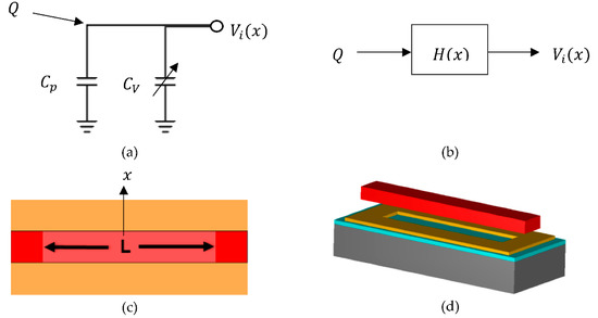
The electrometer is differentially actuated in the x direction by a comb drive. The resonating part is made up of several grounded parallel electrodes. Each one of the electrodes is surrounded by a bottom electrode as seen in Figure 1c,d. We will examine the voltage response of one of these electrodes to derive the charge conversion gain.

Figure 1.
This figure shows conceptual pictures of the variable capacitor. (a) shows a simplified circuit where Cp is the lumped up parasitic capacitances, C𝑣 is the variable capacitor, and 𝑄 is the charge that induces the sense voltage 𝑉𝑖; (b) is a block diagram of the same circuit; (c) is a 2D model of the simple variable capacitor; (d) is a 3D model of (c).
Figure 1a shows a simplified circuit representation of the electrometer, where Cp is the parasitic capacitance and Cv is the variable capacitor. The charge, Q, is applied to the input node of the device resulting in an AC voltage, Vi, due to the variable capacitance. A block diagram representation of this circuit is shown in Figure 1b with transfer function
 𝜖o is the permittivity of free space and g is the gap between the two electrodes. The area between the two electrodes is equal to the length L times the displacement x(t) plus a constant area (represented by the dark color red in Figure 1d). The constant area induces a static capacitance denoted by Co. The displacement is sinusoidal with an amplitude . Since both positive and negative displacement increases the area, the variable capacitance is related to the absolute value of the displacement. Plugging in x (t) and rearranging results in

If we assign the variables Cmax and 𝛼 as
 the transfer function, with respect to time, will be equal to


Equation (1) shows that the output voltage divided by the input charge is equal to the transfer function. It is also true that the derivative of the voltage taken with respect to 𝑄 is equal to the transfer function. This derivative is equal to the charge conversion gain (denoted as ). To find the change in the second harmonic of the output voltage, we perform a Fourier series expansion on Equation (4).

Here, when n is equal to two, 𝑎n is equal to the change in amplitude per charge at the second harmonic. Since H(t) is an even function, the sin product in the summation can be ignored. Solving for 𝑎n gives

The integral was solved empirically and the numerical results agree with MATLAB calculations. The actual measurement to be taken will be equal to the rms value of the second harmonic, which is

3. Discussion
Previous MEMS electrometers created a variable capacitance by varying the gap between electrodes. The charge conversion gain for these devices is [1]

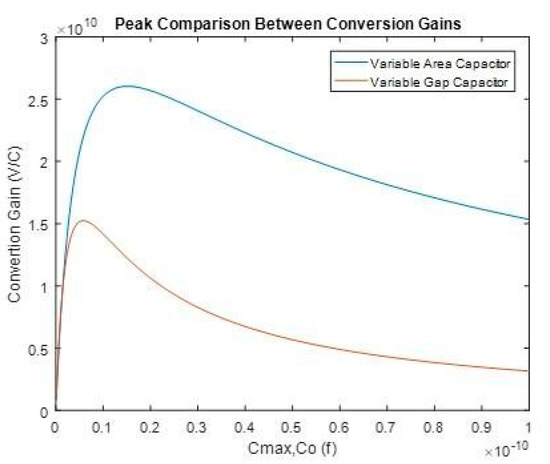
The maximum conversion gains for both Equations (7) and (8) are plotted in Figure 2 with respect to Cmax and Co respectively. Both equations are plotted assuming the same parasitic capacitance. The peak of Equation (7) is nearly 70% larger than the peak in Equation (8), and peaks when Cmax is approximately 2.6Cpo. Equation (8) peaks when Co is equal to Cp.

Figure 2.
Peak comparison between the maximum charge conversion gains of the variable area and gap capacitor electrometers. The plots were created from Equations (7) and (8).
It is necessary to note that obtaining a sense capacitance equal to the parasitic is a difficult task. Still, the new scheme compares well to previous devices when the sense capacitance to parasitic capacitance ratio is small.
Initial simulations show that fringing capacitance can be significant. If the fringing capacitance is high, it can add to the static capacitance and decrease the overall charge resolution. Furthermore, the resolution will be decreased if the derivative of fringing capacitance with respect to displacement is negative.
Physical devices will be created using the PolyMUMPs foundry process. Good agreement between the theoretical and physical results will prove this method of detection to be a viable, cost-effective way to create high-resolution electrometers.
Author Contributions
G.U. Derived the theory for the research; T.L. and G.U. designed the test devices tobe tested; G.U. wrote the paper. All authors have read and agreed to the published version of the manuscript.
Acknowledgments
The authors would like to thank the Air Force Institute of Technology for support and funding of this research. Thanks is extended to MEMSCAP for accepting the PolyMUMPs submission.
Conflicts of Interest
The authors declare no conflict of interest.
References
- Riehl, P.S.; Scott, K.L. Electrostatic Charge and Field Sensors Based on Micromechanical Resonators. J. Microelectromechan. Syst. 2003, 12, 577–589. [Google Scholar] [CrossRef]
- Lee, J.; Zhu, Y.; Seshia, A. Room temperature electrometry with SUB-10 electron charge resolution. J. Micromechan. Microeng. 2008, 18, 025033. [Google Scholar] [CrossRef]
- Jalil, J.; Zhu, Y.; Ekanayake, C.; Ruan, Y. Sensing of single electrons using micro and nano technologies: A review. Nanotechnology 2017, 28, 142002. [Google Scholar] [CrossRef] [PubMed]
- Riehl, P.S. Microsystems for Electrostatic Sensing. Ph.D. Thesis, Department of Electrical and Electronic Engineering, University of California, Berkeley, CA, USA, 2002. [Google Scholar]
- Jaramillo, G.; Buffa, C.; Li, M.; Brechtel, F.J.; Langfelder, G.; Horsley, D.A. MEMS electrometer with femtoampere resolution for aerosol particulate measurements. IEEE Sens. J. 2013, 13, 2993–3000. [Google Scholar] [CrossRef]
Publisher’s Note: MDPI stays neutral with regard to jurisdictional claims in published maps and institutional affiliations. |
© 2018 by the authors. Licensee MDPI, Basel, Switzerland. This article is an open access article distributed under the terms and conditions of the Creative Commons Attribution (CC BY) license (https://creativecommons.org/licenses/by/4.0/).