1. Introduction
Within the past decade, numerous researchers have invested time in the development of micro-electro-mechanical systems (MEMS) micromirror structures which have the ability to deflect at large angles (>20°). These large tip/tilt micromirrors are ideal for many applications to include microscopy, biomedical endoscopy, laser communication, and various other medical instrumentations [
1,
2,
3,
4,
5,
6], just to name a few. Although many of these research efforts exhibit large tip/tilt angles, they generally do not include a piston motion for optical correction requirements or exhibit high fill-factors for large area optical scanning applications. In this research, we present a surface micromachined large angle beam steering micromirror structure which enables tip, tilt, and piston motion so large beam steering arrays can be envisioned at angles >25°. To achieved the desired high fill-factor (>95%), the electrothermal actuation system and the reflective micromirror, are fabricated separately and then integrated together through flip chip bonding. This approach enables the fabrication of the mirror and the actuation system to be completed independently, allowing more rapid incorporation of design modifications into the actuation structure. The research presented in this paper is focused solely on the modeling, fabrication, and testing of the actuation assembly which enables the large angle beam steering.
2. Design Concept
The actuation system is comprised of four, individually controlled electrothermal actuators which are mechanically connected via a torsional spring assembly to a central platform as shown in
Figure 1. The mirror structure will be flip chip bonded to this platform assembly to create the high fill factor array. Due to the bimorph construction of the actuation assembly which consists of an array of integrated beam structures as shown in
Figure 1, the different coefficient of thermal expansion (CTE) of the materials, residual stresses, and beam construction, the central platform will be deflected out-of-plane following release. The torsional spring interconnects between the actuation assembly and the platform enables the torsional twisting and bending necessary such that the platform can physically tip and tilt.
Each actuator is comprised of a series of beams that are designed to maximize the out-of-plane deflection of the platform due to the residual stress and CTE differences. The actuation assembly is composed of a series of five beam pairs all composed of the same material layer composition (SiO
2/aluminum/SiO
2) as shown in the cross-section in
Figure 1.
3. Finite Element Method Model
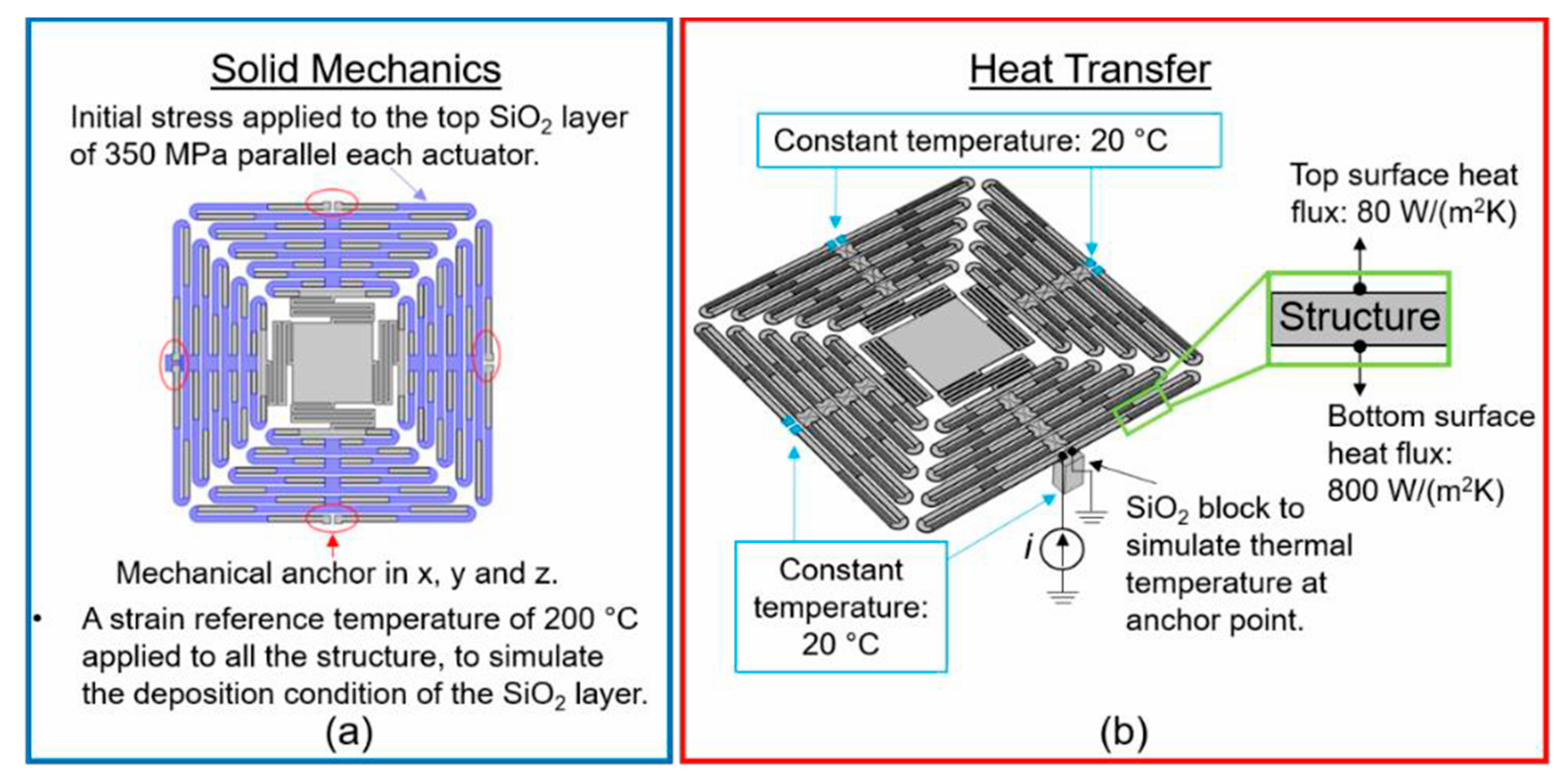
Finite element method (FEM) models were created using COMSOL 5.3a, to simulate the structure from a single beam perspective to eventually a model of the complete actuation assembly. The reduced FEM beam model was used to determine optimal thicknesses of each material layer to achieve the desired initial out-of-plane deflection. From this model, a thickness of 1 µm was determined to be ideal for each material layer to meet the out-of-plane deflections as well as creating the most structurally sound actuation system. A more complex model was then created based off these initial results such that the complete actuation assembly was model as shown in
Figure 2. Two different simulations were performed where the structural geometry and the material layers were identical but the boundary conditions were different. The first simulation was used to determine the initial out-of-plane upward deflection of the actuation system after release (solid mechanics), while the second simulation was to determine the required input current to actuate the structure while also observing the thermal distribution across the actuator (heat transfer). The primary material properties used in the simulations were taken from the built-in COMSOL library to include the electrical conductivity for aluminum (35.5 × 10⁶ S/m), CTE for aluminum (231.1 × 10
−6 1/K) and SiO
2 (0.6 × 10
−6 1/K), heat capacity for aluminum (904 J/kg·K) and SiO
2 (730 J/kg·K), and thermal conductivity for aluminum (237 W/m·K) and SiO
2 (1.4 W/m·K). The boundary conditions for each simulation are illustrated in
Figure 2. For the solid mechanics simulation, the actuators are anchored at the beginning of the structure (red circle) while the complete structure was subject to a strain reference temperature of 200 °C which simulates the deposition temperature of the oxide layers. In addition, an external stress was applied to the top oxide layer to simulate the inherent residual stress between the aluminum layer and the top oxide layer.
In the heat transfer simulations, a temperature of 20 °C was used as the initial thermal condition of the actuation structure. Upon bias, the heat is mainly dissipated through heat conduction, through the material towards the heat sink (anchor). To represent the heat sink at the anchor points of the biased actuator, a SiO2 block was placed in contact with the anchor where the bottom of the block has a constant temperature of 20 °C. This allows the anchor to change temperature as a result of the increased heat generation due to the increased bias potential. The actuators are designed to operate in air, thus there will be some heat dissipation through the air (heat convection). To represent this thermal condition in the model, two different values were used, one for the top and bottom surface of the device. These values were estimated by using the distance (d) between a heat sink and the heat source, and the thermal conductivity of air (𝛷𝑎𝑖𝑟) with the following equation: ℎ𝑒𝑎𝑡 𝑓𝑙𝑢𝑥 = 𝛷𝑎𝑖𝑟⁄𝑑.
The represented heat sink for the bottom surface is the substrate while that of the top heat sink consists of a layer of cold air. The distance of the bottom surface needs to be considered as the elevation of each beam in the actuator assembly is different with respect to the substrate. A simple and conservative estimate value was chosen to be constant between the minimum and the maximum elevation of the beams, with a final value of 50 µm which results in a heat flux of 800 W/(m2·K). The distance for the top surface was chosen to be 500 µm, resulting in a heat flux of 80 W/(m2·K).
4. Results
Similarly to the simulations, the experimental results were measured using two different setups. The initial out-of-plane deflections of the MEMS actuators were measured using the Olympus LEXT OLS4100 laser scanning digital microscope, while the thermal imaging was performed using an infrared camera (OptoTherm, Infrasight MI320), while applying a 20 mA bias current to the actuators. The simulated out-of-plane deflection as shown in
Figure 3a was 484 µm while the measured deflection was 487 µm as shown in
Figure 3b. In order to approximately match the experimental deflection results, a 350 MPa SiO
2 residual biaxial stress level was used in the simulations.
The heat transfer simulation and experimental results are shown in
Figure 4. A common reference point was chosen to measure the temperature of the simulation and the experimental results which provided temperatures of 87 °C and 92 °C, respectively, for a bias current of 20 mA. Furthermore the simulation demonstrates that each actuator was thermally and electrically isolated from each other.
5. Conclusions and Future Work
We presented the design, modeling, and testing of an electrothermal actuation assembly capable of producing large out-of-plane deflections. The actuation system was studied using FEM model to determine and validate different parameters of the design and fabrication results. The solid mechanics simulation helped determine the initial out-of-plane deflection of the structure and was validated with experimental results. Finally, a heat transfer simulation was shown where the unique geometric design of the metal layer was validated both as a heater and as a traditional bimorph structure. Future work will focus on implementing a FEM simulation where the solid mechanics and heat transfer boundary conditions are coupled together to achieve full actuation of the system. On the experimental side, mechanical and thermal studies of the complete system are needed to fully validate the simulation results.
