Abstract
A Current-Mode (CM) TransImpedance Amplifier (TIA) based on Second Generation Current Conveyors (CCIIs) for capacitive microsensor measurements is presented. The designed electronic interface performs a capacitance-to-voltage conversion using 3 CCIIs and 3 resistors exploiting a synchronous-demodulation technique to improve the overall detection sensitivity and resolution of the system. A CM-TIA solution designed at transistor level in AMS0.35 µm integrated CMOS technology with a power consumption lower than 900 µW is proposed. Experimental results obtained with a board-level prototype show linear behavior of the proposed interface circuit with a resolution up to 34.5 fF and a sensitivity up to 223 mV/nF, confirming the theoretical expectations.
1. Introduction
Capacitive sensors can be used in a wide range of applications for the detection of mechanical [1,2], chemical [3,4] and physical [5,6] quantities by measuring capacitance variations. Capacitive sensing has gained a crucial role particularly in Micro Electro-Mechanical Systems (MEMS) where quantities such as acceleration, displacement or pressure have to be measured without generating excessive electrostatic forces on the capacitive sensing element [7,8,9,10]. A TransImpedance Amplifier (TIA) based on Second Generation Current Conveyors (CCII) with good performances in terms of linearity, sensitivity, resolution and capability to reveal large dynamic ranges of capacitance sensor variations is proposed. In particular, with respect to voltage-mode architectures based on Operational Amplifiers (OAs), CCII-based Current-Mode (CM) solutions are mainly suitable for their integration in a standard CMOS technology through simple architectures with a reduced number of transistors, within a small silicon area and having low-power characteristics [11,12,13]. The use of CCII promotes the design of integrated circuits for portable sensor applications, overcoming constraints typically provided by circuits based on OAs, ensuring a larger frequency bandwidth and a good capability to work at low supply voltage levels with a wide input-output dynamic range [14,15]. The proposed CM-TIA description and operating principle are illustrated in Section 2, experimental results are presented in Section 3, and conclusions are given in Section 4.
2. Current-Mode Transimpedance Amplifier
The block diagram of the CM-TIA is shown in Figure 1a while Figure 1b reports the schematic circuit of the proposed CCII designed at transistor level in AMS0.35 µm CMOS integrated technology with a power consumption lower than 900 µW at ±1 V dual supply voltage. Time and frequency domain simulation results of the integrated CM-TIA are reported in Figure 2. The current is(t) produced by the excitation sinusoidal signal vs(t) applied to the capacitance under test Cx is applied to the CCII1 low-impedance input X. The three resistors R1 = 100 kΩ, R2 = 51 kΩ and R3 = 100 kΩ set the total gain of the TIA:
G = vt(t)/is(t) = (2R1R3)/R2
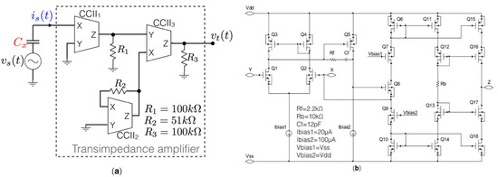
Figure 1.
(a) Block diagram of the CCII-based transimpedance amplifier. (b) Transistor-level CCII schematic circuit.
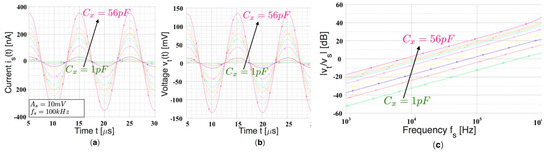
Figure 2.
Time domain simulation results showing (a) the input signals is(t) and (b) vs(t) for different capacitance values Cx. The resulting transimpedance gain G is about 390 kΩ. (c) Frequency simulation.
Thanks to the virtual ground at the CCII1 X node, the current is(t) is given by:
is(t) = 2πfsCx vs(t)
The output voltage of the TIA vt(t) is then equal to:
vt(t) = G 2πfsCx vs(t)
3. Experimental Results
A board-level prototype of the TIA has been implemented with three commercial CCII (AD844) for preliminary measurements as shown in Figure 3. The experimental frequency responses of the board-level CM-TIA obtained using different reference capacitances within the range of 1–56 pF are reported in Figure 4.

Figure 3.
(a) Bottom view of the implemented board-level CM-TIA prototype. (b) Experimental setup.
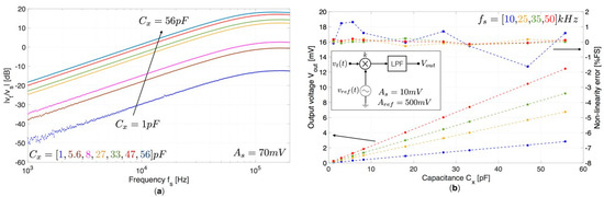
Figure 4.
(a) Magnitude of the ratio vt/vs as a function of the frequency fs obtained for different values of reference capacitance Cx. (b) Measured output voltage Vout as a function of the reference capacitance Cx for different values of fs. Raw data are represented with dots while dotted-lines represent fittings with a first-order polynomial. The calculated non-linearity error as a function of Cx is also reported considering as full-scale FS the maximum output voltage Vout obtained at each operating frequency.
A good agreement with the theoretical behavior is obtained, showing a linear trend for frequencies up to 80 kHz, exhibiting a lower bandwidth with respect to the proposed optimized integrated version, as reported in Figure 4a. A synchronous demodulation has been implemented to provide a DC output voltage and improve the signal-to-noise ratio by using an analog multiplier (AD835) and a low-pass filter as reported in the inset of Figure 4b. The sinusoidal reference voltage vref(t) has a peak amplitude Aref = 0.5 V and a nominal phase shift ϕ = −90 deg with respect to the excitation signal vs(t) whose peak amplitude is As = 10 mV. The DC output signal is equal to:
where k = 1.05 V is the multiplier gain factor. Figure 4b shows the measured output voltage Vout as a function of the reference capacitance Cx obtained at different frequency values fs of 10, 25, 35, 50 kHz. Experimental results are in good agreement with the expected values, showing a good linearity within the measurement range. The obtained maximum sensitivity is about 223 mV/nF for fs = 50 kHz with an estimated resolution calculated at 3 = 7.68 µV of about 34.5 fF.
Vout = 0.5 k−1 G As Aref 2πfsCx cos(ϕ + 90)
4. Conclusions
A current-mode transimpedance amplifier based on second generation current conveyors able to measure capacitive variation with low sensing signal amplitude has been presented.
The integration of CCII promotes the design of low-power integrated circuits, overcoming restraints typically provided by circuits based on operational amplifiers, ensuring a larger frequency bandwidth and a good capability to work at a low supply voltage levels with a wide dynamic range. The proposed electronic interface performs a capacitance-to-voltage conversion using 3 CCIIs and 3 resistors exploiting a synchronous-demodulation technique to improve the overall sensitivity and resolution of the system. Experimental results obtained with a board-level prototype have led to a sensitivity of about 223 mV/nF for fs = 50 kHz with an estimated resolution calculated at 3 = 7.68 µV of about 34.5 fF. The obtained values of sensitivity and resolution show that the proposed CM-TIA is suitable for capacitive measurement of comb-finger parallel-plate MEMS sensors.
Conflicts of Interest
The authors declare no conflict of interest.
References
- Xia, F.; Campi, F.; Bahreyni, B. Tri-mode capacitive proximity detection towards improved safety in industrial robotics. IEEE Sens. J. 2018, 18, 5058–5066. [Google Scholar] [CrossRef]
- Lee, J.C.; Yang, S.H. Development of nanopositioning mechanism with real-time compensation algorithm to improve the positional accuracy of a linear stage. Precis. Eng. 2017, 50, 328–336. [Google Scholar] [CrossRef]
- Molinnus, D.; Muschallik, L.; Gonzales, L.O.; Bongaerts, J.; Wagner, T.; Selmer, T.; Siegert, P.; Keusgen, M.; Schöning, M.J. Development and characterization of a field-effect biosensor for the detection of acetoin. Biosens. Bioelectron. 2018, 115, 1–6. [Google Scholar] [CrossRef] [PubMed]
- Zhao, Y.; Yang, B.; Liu, J. Effect of interdigital electrode gap on the performance of SnO2-modified MoS2 capacitive humidity sensor. Sens. Actuator B Chem. 2018, 271, 256–263. [Google Scholar] [CrossRef]
- Ren, Y.; Pan, M.; Chen, D.; Tian, W. An Electromagnetic/Capacitive Composite Sensor for Testing of Thermal Barrier Coatings. Sensors 2018, 18, 1630. [Google Scholar] [CrossRef] [PubMed]
- Xue, N.; Gao, G.; Sun, J.; Liu, C.; Li, T.; Chi, C. Systematic study and experiment of a flexible pressure and tactile sensing array for wearable devices applications. J. Micromech. Microeng. 2018, 28, 075019. [Google Scholar] [CrossRef]
- Aydemir, A.; Terzioglu, Y.; Akin, T. A new design and a fabrication approach to realize a high performance three axes capacitive MEMS accelerometer. Sens. Actuator A Phys. 2016, 244, 324–333. [Google Scholar] [CrossRef]
- Nastro, A.; Ferrari, M.; Russo, A.-L.; Ardito, R.; Ferrari, V. MEMS force sensor with DDS-based position feedback and tunable sensitivity. In Proceedings of the IEEE Sensors Conference, Glasgow, Scotland, 29 October–1 November 2017. [Google Scholar] [CrossRef]
- Nastro, A.; Ferrari, M.; Russo, A.-L.; Ardito, R.; Ferrari, V. Servo-Assisted Position-Feedback MEMS Force Sensor with Tunable Sensitivity and Sub-Nanonewton Range. In Proceedings of the Eurosensors17 Conference, Paris, France, 3–6 September 2017. [Google Scholar] [CrossRef]
- Cerini, F.; Ferrari, M.; Ferrari, V.; Russo, A.; Urquia, M.A.; Ardito, R.; de Masi, B. Electro-Mechanical Modelling and Experimental Characterization of a High-Aspect-Ratio Electrostatic-Capacitive MEMS Device. Sens. Actuators A Phys. 2017, 266, 219–231. [Google Scholar] [CrossRef]
- De Marcellis, A.; Di Carlo, C.; Ferri, G.; Stornelli, V. A CCII-based wide frequency range square waveform generator. Int. J. Circuit Theory Appl. 2013, 41, 1–13. [Google Scholar] [CrossRef]
- López-Martín, A.J.; Ramirez-Angulo, J.; Carvajal, R.G. Highly accurate CMOS second generation current conveyor and transconductor. In Proceedings of the IEEE EUROCON, Salamanca, Spain, 8–11 September 2015. [Google Scholar] [CrossRef]
- Reda, A.; Ibrahim, M.F.; Farag, F. Input–output rail-to-rail CMOS CCII for low voltage–low power applications. Microelectron. J. 2016, 48, 60–75. [Google Scholar] [CrossRef]
- De Marcellis, A.; Ferri, G.; Mantenuto, P. A CCII-based non-inverting Schmitt trigger and its application as astable multivibrator for capacitive sensor interfacing. Int. J. Circuit Theory Appl. 2017, 45, 1060–1076. [Google Scholar] [CrossRef]
- De Marcellis, A.; Palange, E.; Liberatore, N.; Mengali, S. Low-cost portable 1MHz lock-in amplifier for fast measurements of pulsed signals in sensing applications. IEEE Sens. Lett. 2017, 1, 1–4. [Google Scholar] [CrossRef]
Publisher’s Note: MDPI stays neutral with regard to jurisdictional claims in published maps and institutional affiliations. |
© 2018 by the authors. Licensee MDPI, Basel, Switzerland. This article is an open access article distributed under the terms and conditions of the Creative Commons Attribution (CC BY) license (https://creativecommons.org/licenses/by/4.0/).