Proceeding Paper

Resonant Accelerometer based on Double-Ended Tuning Fork and a Force Amplification Mechanism †

by
Eurico Esteves Moreira
1,2,*,
Burkhard Kuhlmann
3,
João Gaspar
2 and
Luis Alexandre Rocha
1,2
1
CMEMS-UM, University of Minho, 4800-058 Guimarães, Portugal
2
MeN, International and Iberian Nanotechnology Laboratory (INL), 4717-330 Braga, Portugal
3
Robert Bosch GmbH, 72762 Reutlingen, Germany
*
Author to whom correspondence should be addressed.
Presented at the Eurosensors 2018 Conference, Graz, Austria, 9–12 September 2018.
Proceedings 2018, 2(13), 1030; https://doi.org/10.3390/proceedings2131030
Published: 13 November 2018
(This article belongs to the Proceedings of EUROSENSORS 2018)

Abstract

:
Resonant accelerometers are an alternative to amplitude modulated devices due to their higher integration capabilities, since they are encapsulated in vacuum and are stable at low pressures. Vacuum is required for some sensors (i.e., gyroscopes) but amplitude modulated accelerometers tend to be unstable under such conditions and therefore cannot be integrated in the same package. Herewith, a device composed by double-ended tuning fork resonators (DETF) and a force amplification mechanism for sensitivity enhancement is presented. Characterization of the fabricated devices was performed, and the design was successfully validated. A sensitivity close to 80 Hz/g was experimentally measured and the DETF characterization for different driving (AC) and bias voltages (DC) is also presented.

1. Introduction

The endless quest for smaller, cheaper and more integrated systems led to several studies on alternatives to amplitude modulated accelerometers, as those devices suffer from lack of stability when encapsulated in vacuum. Two main alternatives are available, the use of closed-loop mechanisms such as sigma-delta [1] and frequency modulated devices [2]. Resonant MEMS are a promising solution, since their readout circuit is less power consuming than their capacitive alternative, they can be fabricated on standard MEMS processes and they are immune to pull-in [3]. Lately, frequency modulated MEMS sensors had proven themselves suitable in many applications and several authors have presented gyroscopes [4], accelerometers [2] and inclinometers [5]. Here, a frequency modulated accelerometer composed by DETF resonators on a differential architecture is presented. Regarding the resonators, single-beam [2] and DETF [5] are commonly used since they are sensitive to stress applied to their extremities. Despite a higher sensitivity reported on single-beam accelerometers (due to their lower cross-sectional area), DETF benefits from zero net force at the anchors and a higher quality factor [6]. Although, the sensor here presented has a capacitive readout, piezoelectric materials can be deposited on top of the resonators beams, simplifying the electronics, but unfortunately, those devices are usually prone to a high temperature dependency [7].

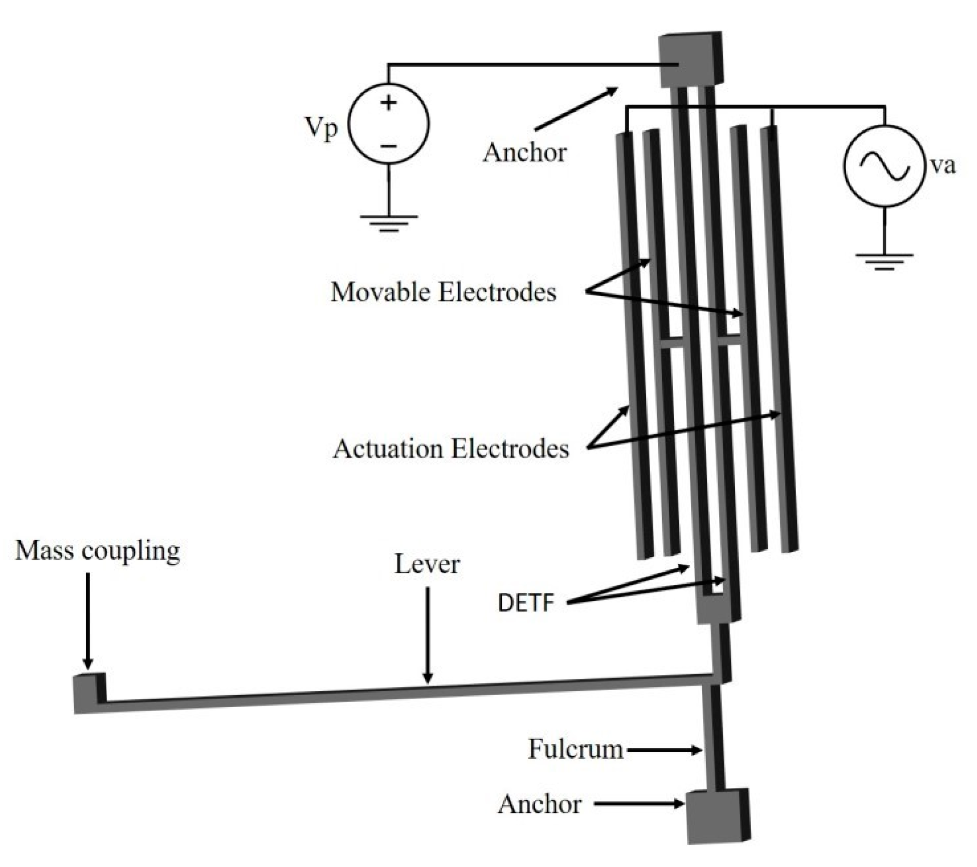
2. Accelerometer Design

A resonant accelerometer is constituted by stress sensors (i.e., single beam or DETF) coupled to a proof mass that induces a stiffness change on the beams and consequently a shift in their resonance frequency proportional to the external acceleration. However, the lack of sensitivity, usually few Hz/g, are a drawback in the use of those resonant devices. This can be overcome by using a force amplification mechanism. Several options are available accordingly to the footprint and amplification factor desired, namely, single-stage [2] and dual-stage levers [8]. Those mechanisms increase the force applied to the stress sensitive structures, based on the relation of the input/fulcrum and output/fulcrum distances. One knows, that using the standard MEMS processes, an ideal fulcrum is impractical, and therefore the amplification gain is more difficult to predict. Therefore, an amplification/sensitivity optimization of the sensor was performed linking a parametric CAD design with a FEM tool, enabling a complete study on the importance of each feature on the device behavior. The design here introduced has a first-class lever with a flexible pivot (see Figure 1), increasing the theoretical sensitivity to approximately 50 Hz/g.
Additionally, a differential approach was adopted, doubling the frequency shift and minimizing common mode errors, such as, temperature dependency. The structures (0.45 × 0.45 mm2) were fabricated on a commercial process (see Figure 2) and sealed with a silicon lid at low pressure (150 Pa).

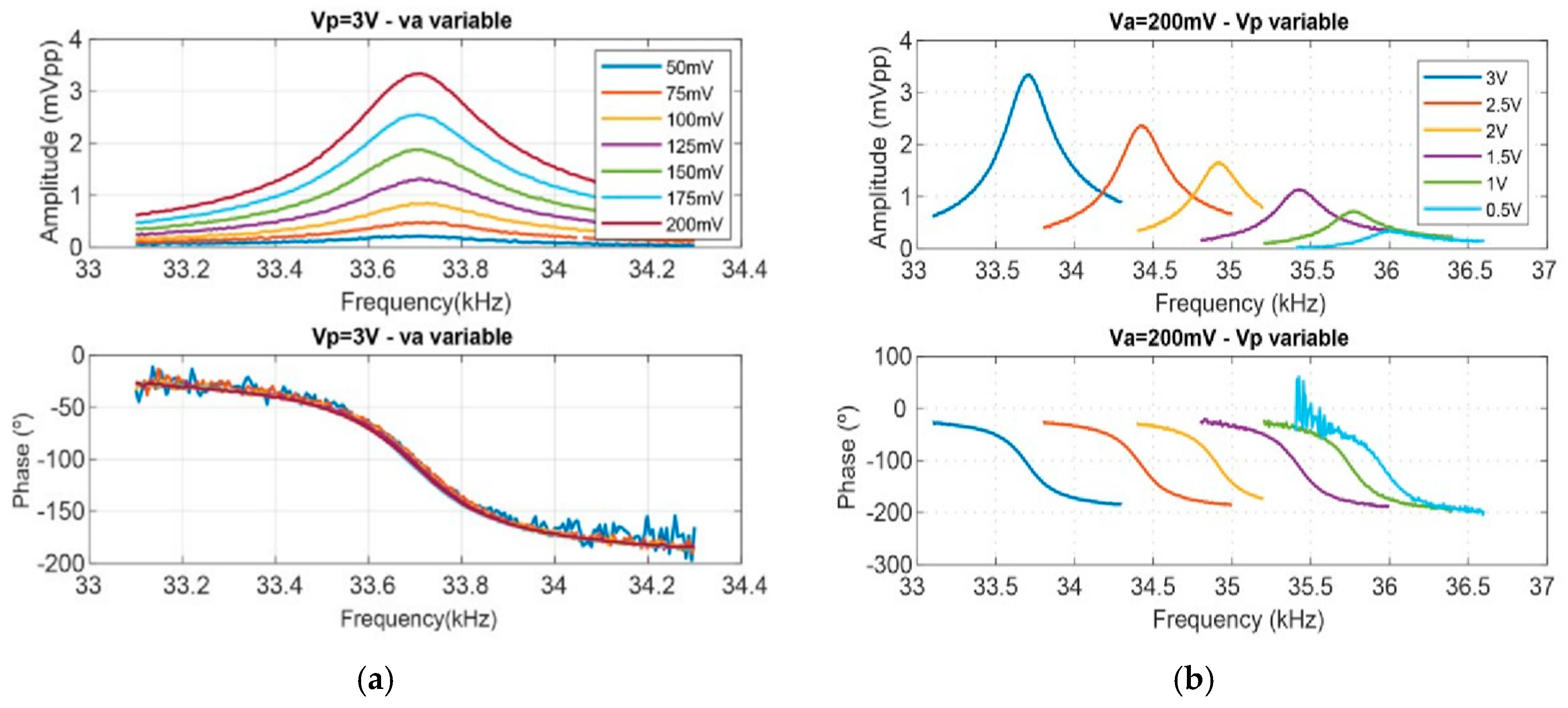
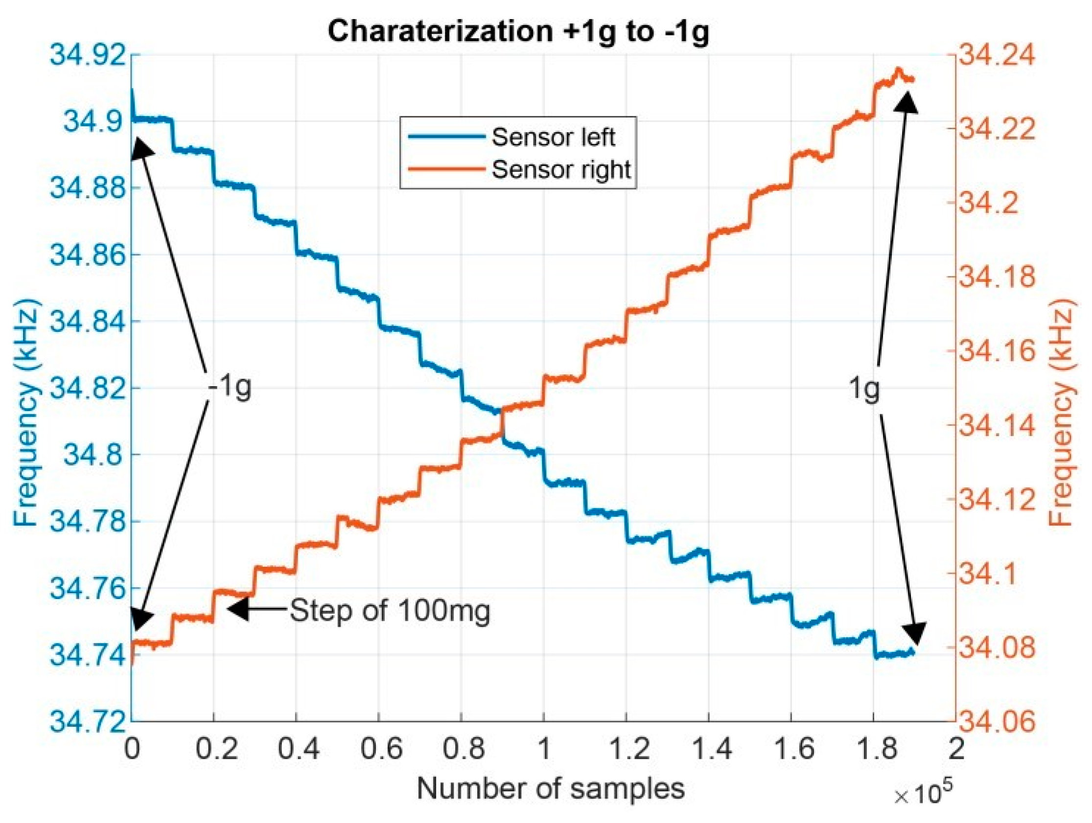
3. Experimental Results

After the packaging process, the structures were characterized. First, a frequency sweep was performed, and a quality factor close to 120 was experimentally measured. Then, the DETFs were characterized for different driving (va) and bias (Vp) voltages, being va an AC signal and Vp a DC voltage. Experimentally it is shown that the resonator natural frequency does not change with a higher driving voltage but the amplitude of signal increases, as shown in Figure 3a. Nonetheless, a rise in the bias voltage leads to a lower resonance frequency due to the negative spring effect caused by a higher electrostatic force (see Figure 3b), as theoretically expected. The measurements were made using a lock-in amplifier and a transimpedance amplifier.
Sensitivity measurements were performed adding a proportional controller that updates the driving voltage accordingly to the resonant frequency of the sensor. The structures were tested from −1 g to +1 g and an experimental sensitivity of 80 Hz/g was obtained. Both DETF of the differential design were characterized as presented in Figure 4.

4. Conclusions

A resonant accelerometer composed by DETF resonators, a central mass and a force amplification mechanism (first-class levers) is presented. The devices were fabricated with a Bosch MEMS process that allows vacuum packaging and their small size (approximately 0.45 × 045 mm2) is advantageous. Subsequently, the sensors were characterized using a system composed by a transimpedance amplifier, a lock-in amplifier and a proportional controller. This system follows in real time the natural frequency of the DETF and automatically adjusts the driving voltage frequency. A quality factor near 120 was experimentally measured and the effect of the driving and bias voltages on the sensor behavior was studied. Additionally, the structures were tested in the range [−1 g, +1 g] showing a sensitivity of 80 Hz/g.

Acknowledgments

The first author is supported by FCT– Fundação para a Ciência e Tecnologia through the grant PDE/BDE/114564/2016. This work is supported by FCT with the reference project UID/EEA/04436/2013, COMPETE 2020 with the code POCI-01-0145-FEDER-006941.

Conflicts of Interest

The authors declare no conflict of interest.

References

  1. Dong, Y.; Zwahlen, P.; Nguyen, A.M.; Frosio, R.; Rudolf, F. Ultra-high precision MEMS accelerometer. In Proceedings of the 2011 16th International Solid-State Sensors, Actuators and Microsystems Conference, Beijing, China, 5–9 June 2011; pp. 695–698. [Google Scholar]
  2. Comi, C.; Corigliano, A.; Langfelder, G.; Longoni, A.; Tocchio, A.; Simoni, B. A Resonant microaccelerometer with high sensitivity operating in an oscillating circuit. J. Microelectromech. Syst. 2010, 19, 1140–1152. [Google Scholar] [CrossRef]
  3. Caspani, A.; Comi, C.; Corigliano, A.; Langfelder, G.; Tocchio, A. Compact biaxial micromachined resonant accelerometer. J. Micromech. Microeng. 2013, 23, 105012. [Google Scholar] [CrossRef]
  4. Zega, V.; Comi, C.; Minotti, P.; Langfelder, G.; Falorni, L.; Corigliano, A. A new MEMS three-axial frequency-modulated (FM) gyroscope: A mechanical perspective. Eur. J. Mech. A/Solids 2018, 70, 203–212. [Google Scholar] [CrossRef]
  5. Wang, S.; Wei, X.; Weng, Y.; Zhao, Y.; Jiang, Z. A novel single-axis MEMS tilt sensor with a high sensitivity in the measurement range from 0° to 360°. Sensors 2018, 18, 346. [Google Scholar] [CrossRef]
  6. Kaajakari, V. Practical MEMS: Design of Microsystems, Accelerometers, Gyroscopes, RF MEMS, Optical MEMS, and Microfluidic Systems; Small Gear Publishing: Las Vegas, NV, USA, 2009. [Google Scholar]
  7. Wang, Y.; Ding, H.; Le, X.; Wang, W.; Xie, J. A MEMS piezoelectric in-plane resonant accelerometer based on aluminum nitride with two-stage microleverage mechanism. Sens. Actuators A Phys. 2017, 254, 126–133. [Google Scholar] [CrossRef]
  8. Su, S.X.P.; Yang, H.S. Analytical modeling and FEM simulations of single-stage microleverage mechanism. Int. J. Mech. Sci. 2002, 44, 2217–2238. [Google Scholar] [CrossRef]
Figure 1. Schematic of a DETF coupled to a force amplification mechanism, namely a first-class lever. All the features and the electrical connections are represented.
Proceedings 02 01030 g001
Figure 2. SEM images of a resonant accelerometer.
Proceedings 02 01030 g002
Figure 3. (a) Several frequency sweeps performed with a bias voltage of 3 V and different driving voltages. (b) Characterization of the resonator for different bias voltages and a fixed driving voltage of 200 mV.
Proceedings 02 01030 g003
Figure 4. A device was dynamically characterized from +1 g to −1 g and a motor with a high rotational precision was used to make steps of 100 mg. Furthermore, the system implemented was able to update in runtime the driving voltage to the natural frequency of both sensors present on the differential configuration.
Proceedings 02 01030 g004
Publisher’s Note: MDPI stays neutral with regard to jurisdictional claims in published maps and institutional affiliations.

