1. Introduction
The community is looking for a new manner to improve wastewater (WW) treatment efficiency, recycling and reuse treated water [
1,
2,
3,
4]. This work provides the first part of optimizing sludge management (SM) as a case study focusing on comparison of sludge dewatering technology, pilot testing unit in the real condition and design of optimized SM. This paper represents only the first part of applied research and at the second part, currently our research is focused on selection of the most suitable combination of polymers for dewatering.
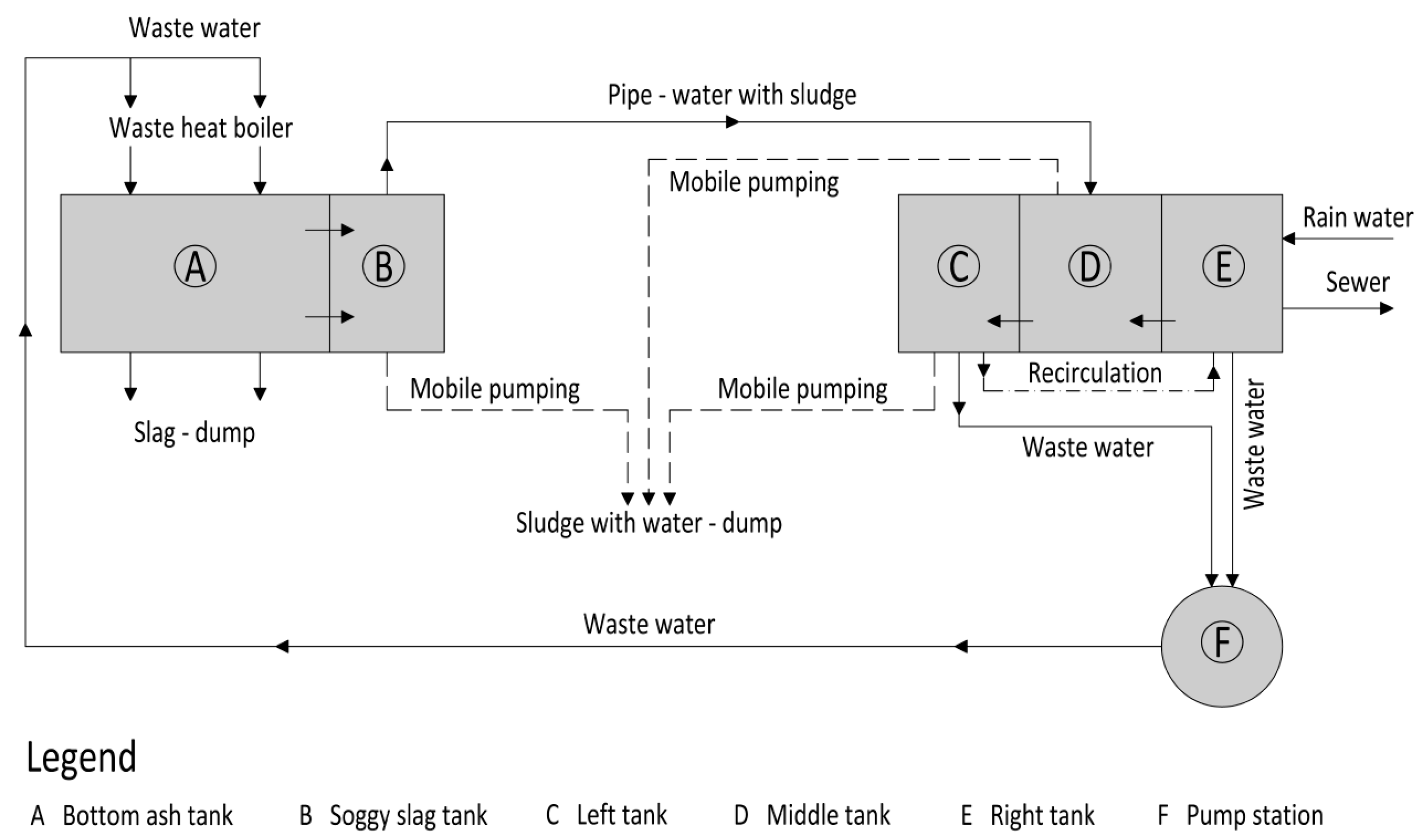
The existing SM system at the SAKO Brno, a.s. municipal solid waste incinerator (MSWI) consists in the dewatering of slag from boilers in the slag building. This soggy slag is conveyed along the bottom through entries to the bottom ash tank. Fine fractions settle in this bottom ash tank. Soggy water overflows into gravity sewerage and is then discharged into an outside retention tank. The retention tank consists of three parts: middle tank, left tank and right tank. The existing technologies generate excessive volumes of sludge that must be regularly extracted and transported off site for disposal by a specialised company approximately once a month. The volume of sediments disposed of by the specialised company is ca. 50 m
3 a month. WW is conveyed by discharge pipes along with storm water via 4 pumps to the flue gas sprinkling technology. This establishes a technological cycle at the MSWI as shown in
Figure 1.
The original SM conception at MSWI was supposed to be waste-free compared to competitive landfill sites [
4]. However, the current operation has shown that there is a need to ensure regular extraction and disposal of settling sludge from the bed of the bottom ash tank and the retention tank. There is excessive polluted storm water that needs to be treated so that it can be discharged into the sewer system or utilised in a different manner. The current condition of the SM system causes not only operating problems related to the MSWI technological process downtimes but also major financial issues related to the solutions of regular tank cleaning.
The traditional waste management system using a wastewater treatment plant (WWTP) including chemical management, absorption, neutralization, sedimentation and dewatering, appears demanding in terms of investments and operation [
5]. Therefore, it is necessary to propose SM optimization at the MSWI based on a suitable technology of mineral sludge thickening [
6].
Furthermore, pilot testing of the selected equipment in realistic conditions is advisable to be carried out at the MSWI. If needed, flocculation tests of selected soggy slag sludge dewatering flocculants should be conducted and evaluated and treated WW utilization should be proposed. In thus paper, the flocculation is considered sludge conditioning to improve the sludge dewaterability. We expect the use of flocculants, i.e., synthetic polymers that are highly efficient in WW flocculation [
7]. Nevertheless, these synthetic flocculants are not as environmental-friendly asnatural flocculants [
8]. The resulting dewatered sludge with the use of flocculants can be marked as physical-chemical sludge [
6]. The aim of the applied research presented in this paper is SM optimization by a mobile SW press unit with optimal polymer combination for DW which are currently being clarified.
2. Materials and Methods
Currently, SM means that service water is used to sprinkle the equipment in the flue gas cleaning building where the polluted service water with sludge gets to the bottom ash tank. The bottom ash tank is an open reinforced concrete basin with a local bottom reinforcement from where the slag is extracted using a grab crane. The polluted service soggy slag is conveyed through entries with fitted stainless steel sieves into the soggy slag tank, which is a closed reinforced concrete tank with bottom and walls lined with basalt. The final sludge fraction from flue gas technology of slag cooling settles here. Polluted service water is discharged from the soggy slag tank via a gravity concrete pipe DN 400 outside the building to the external retention tank.
The retention tank is divided into 3 separate spaces, i.e., right rainwater tank, soggy slag middle tank with two built-in mixers, flocculant dosing system and scraping device for sludge sediments where soggy slag flows out at the end of the scraping system through an opening to the side third left tank with soggy slag free of sediments. The DN 400 pipe discharges into the middle space where waste soggy slag is mixed by means of slow-moving mixers installed on a composite platform with the flocculant in a built-in room of a rectangular ground plan. WW then flows through the bottom of the rectangular built-in space in a longitudinal direction through the middle space via the scraping system. Settling sludge is collected under the mixers, under the rectangular built-in space, nevertheless, a part of fine fraction settles also in the side left tank. Water is extracted by horizontal pumps back to the technological process lue gas equipment sprinkling from the side space where the settled soggy slag is stored. Pumps are installed in the basement in a separate civil structure close to the retention tank. The equipment has been recently reconstructed here. In the basement, there are 4 pumps extracting settled soggy slag and rainwater which is collected from adjacent bituminous surfaces. These pumps also pump water to sprinkle boilers using a delivery pipe. This pipe gets often clogged, incrustation is formed and the operator then flushes the pipe using a solution of water an acid out of the flue gas building back to the retention sump.
2.1. Technology for Sludge Dewatering
The WW treatment technology, i.e., treatment of soggy slag with a high pH value, fluctuating and high levels of dissolved solids, chlorides, fine sediment fractions and high heavy metal (HM) content disabling discharge into the sewerage system fails to follow the sewerage regulations, see the point analysis values in comparison with the values specified in the sewerage regulations, see
Table 1. If the values were to meet the sewerage regulations, the technology would have to include technological processes consisting of neutralization, precipitation, evaporation and sludge thickening. With regard to the technologically demanding processes and taking into account high investments and operational demands, the method of soggy slag treatment enabling its discharges into municipal sewerage is not further assessed. Only sludge thickening technology or technology thickening sediments from the bottom ash tank and the retention tank is considered.
The technology treating soggy slag with high pH (around 12), fluctuating and high values of dissolved solids DS, chlorides, fine sediment fractions and high content of HM is problematic. Slag production is ca. 48,000 t of slag a year, maximum inflow to the retention tank, with sand filter flushing, is ca. 40 m
3∙h
−1. For comparison, the MSWI Termizo processes 91,165 t of slag a year, which in terms of SM represents 21,882 m
3∙year
−1 of WW and 792 t∙year
−1 of HM in filter cake [
5]. It is necessary to consider application of continuous and discontinuous operation. To assess soggy slag sludge dewatering (DW), which may be called mineral sludge [
6], sludge thickening technologies were selected and compared: chamber filter press, screw dehydrator (DW press) [
9] and belt press.
These 3 pieces of equipment were tested, i.e., 20 L of representative samples of soggy sludge were taken from the bottom of the central part of the retention tank and then submitted to the representatives of the equipment manufacturers for sedimentation tests and representative dewatering using the specific equipment.
With respect to Czech standard ČSN EN 12255-13 [
10] and ČSN EN 12255-8 [
11] the proposed mechanical equipment must respect the sludge properties, scope and concentration of solids, physical characteristics of WW with sludge, aggressive and corrosive conditions, effects of abrasive substances and effects of additives used in WW treatment, i.e., flocculants.
2.2. Chamber Filter Press
A testing chamber filter press was studied at the MSWI plant in Prague, where this technology has been in operation for more than 1 year to dewater soggy slag from the MSWI plant. Additionally, a chamber filter press was studied in a private company in Brno, where the filter press is used to process waste from metallurgical industry. On the basis of a representative 20 L sample of soggy slag taken at SAKO Brno, a.s. for laboratory testing in laboratories operated by a company supplying chamber filter press.
2.3. Sludge Dewatering Press
Another alternative mechanical equipment for DW from the soggy slag tank and retention tank is a screw dehydrator which was studied at the production plant of the machinery supplier in Prague, followed by a study of an installed screw dehydrator in a representative municipal WWTP. Just like in the case of the chamber filter press, a representative sludge sample in a volume of about 20 L was provided in order to determine the volume of sludge sample dewatering by the sludge dewatering press.
2.4. Belt Filter Press
The third alternative equipment for DW from the bottom ash tank and retention tank was a belt press in Slovakia. This belt press was studied and also tested in the MSWI in Slovakia, it was studied at the premises of the machinery supplier. As in the previous cases, a representative sludge sample of approximately 20 L was provided along with an attached sampling protocol in order to determine the possibility of dewatering the sample using a belt press. Demonstrative DW tests were conducted in order to simulate dewatering by a belt press. The sludge was mixed with anionic flocculant which caused sludge flocculation. Subsequently, sample dewatering using the belt press was performed. The dewatered sludge showed a high degree of dewatering, separation was simple and meshes did not get clogged. The dewatered water showed a low content of undissolved SS and this water is suitable, for example, for equipment rinsing.
2.5. Pilot Testing in Real Conditions
After the first review of collected information concerning the assessment and evaluation of 3 various pieces of equipment for soggy slag DW it seems that the sludge dewatering press facility [
9] is potentially suitable. To test the suitability of the equipment, a pilot sludge dewatering press was transported and installed on a steel pallet. The pilot screw dehydrator unit was commissioned first at the bottom ash tank in September 2016.
Flocculants are hydrophilic polymers having a molecular weight varying from 1 to 30 million, i.e., a degree of polymerization of between 14,000 and 420,000 monomer units. Their water solubility comes from sufficiently strong solvation of the polar groups (either ionic or non-ionic) that they contain, so that the various segments of a chain are dissociated. Usually based on acrylamide, they have, by homopolymerization, a nonionic nature and may have, by copolymerization, a cationic or anionic nature [
12].
During the test, two different types of flocculants, i.e., structurally-chained polymers, were tested: Kemira Superfloc C-1596 from Kemira and Praestol A 3040 L from Solenis. Both these aforementioned types of flocculants were characterized by good separation of suspended solids and a similar size of flocs—5–7 mm. However, the flocs thus formed did not have sufficient strength when applying pressure in the dewatering drum. As a result, individual flocs were ruptured, which subsequently adversely affected the quality of separated filtrate. This fact was caused by a significant sludge variability at the dewatering inlet of 0.4–1.5%. This affected the quality of interaction between the dosed flocculant and suspended solids contained in WW. Optimal flocculation was achieved only periodically at times when the sludge concentration was temporarily stable. This fact negatively affected presentation of automatic operation when the flocculant dosage had to be constantly controlled depending on the current concentration of input sludge. To improve the efficiency of flocculation in cases of permanent changing of the sludge quality could be recommended the installation of a sensor that monitors the feed solids.
Output concentrations of thickened sludge were analysed at 26%. The application of pressure in the dewatering cylinder was considerably reduced mainly due to the fragility of individual flocs. With regard to unstable operating conditions and variation of the sludge input concentration, laboratory flocculation tests of selected flocculants were conducted.
2.6. Flocculation Tests
Based on the experience with difficult flocculation during the pilot unit testing, was 25 L of a representative sample of soggy slag was taken. The representative sample was taken from the retention tank, sludge concentration at 2.69%, pH 12.
The flocculation tests were performed in a laboratory of CHEM.ENGI s.r.o., test principles followed TNV 75,7961 Determination of sludge thickening and dewatering properties [
13]. Flocculants, suitable for mechanical industry and sludge treatment were selected: anionic and cationic flocculant [
12]. On the polymer selection test were used the combination of polymers with the commercial name YESfloc: coagulants PA100 and YESfloc PG in different dilution 20, 50% and flocculants: CWE823, AWE30, CWE35 with dilution 0.5%; 1.0%; 3.0%. A suitable selection of flocculant means a volume of polymer, smaller volume of dewatered sludge, which saves 25–30% of opex [
14]. They could be structured as copolymers of acrylamide which are used in water industry. Flocculant could be used in a production lines of different industries, as are mining, cosmetics etc. In copolymers with acrylamide, hydrolysis of the ester groups has been investigated and found to be CD and pH dependent with hydrolysis increasing under more alkaline conditions [
15].
To assess the flocculating tests variants, a methodology was defined based on the visual evaluation. To make laboratory assessment of the soggy slag representative sample dewatering efficiency, repetition followed characterisation for category C1–C4.
3. Case Study of SAKO Brno
Three pieces of equipment were tested: a testing chamber filter press, sludge dewatering press and belt filter press.
A testing chamber filter press: the dry solids content of the sample was determined at 1.9%, the sediment dry solids content was 10.1%. When filtration was performed on the chamber filter press at 14 bars: a hard, almost brittle, filter cake with a dry solids content of 48.6% and bulk density of 1600 kg·m−3 was produced. Filtration was then carried out on a 6-bar chamber filter press. A hard, almost brittle, filtration cake with a dry solids content of 46.9% and bulk density of 1550 kg·m−3 was produced. On the basis of the performed laboratory tests and based on filtration carried out at 14 bars and at 6 bars, a chamber filter press with a capacity of 5 m3 of suspension per week is recommended.
Sludge dewatering press: a dewatering test was performed on the provided sample but it was not possible to determine suitability of a particular polymer and therefore the tests were not completed and testing using a small DW press was proposed instead in order to confirm or disprove the suitability of installing this equipment.
Belt filter press: results of the laboratory tests of the belt press are as follows: dry solids content in the tested sample 6.3%, dry solids content after dewatering 39.4%, consumption of flocculant-sokoflok 26 anionic 1.2 kg per 1 ton of dry solids, dry solids content in pressed cake approx. 40%. The test showed that the sludge is also dewaterable with the help of a chamber filter press in combination with membrane post-pressing. A prototype belt press was installed at the MSWI, Slovakia. This unit has an output of ca. 5 m3·h−1.
The sludge dewatering press pilot unit testing validated application of equipment for SM optimizing at the MSWI with a requirement for the selection of a suitable flocculant, specifically polymer. The comparison of various equipment for soggy slag sludge dewatering is shown in
Table 2. The results of dewatering the representative sample were compared with the performance of proposed equipment. Besides these two parameters we also assessed the advantages and disadvantages of the considered mechanical equipment for soggy slag sludge dewatering such as: automated operation, operating demands, discontinuous operation, service availability and, last but not least, acquisition price.
The main preferred advantages are: minimal requirements for operation (automated operation), minimum cleaning requirements, discontinuous operation, the expected lower dewatering efficiency is not considered a disadvantage—these requirements are met by the sludge dewatering press. The sludge dewatering press was selected despite the defined disadvantages-high price, high abrasiveness of particles causes degradation to movable slats and screws. In order to verify the right selection of the equipment, pilot testing of a small sludge dewatering press was conducted under real conditions at the MSWI SAKO Brno, a.s.
Two flocculants were used during the pilot testing, which did not fully meet the expectations. Therefore, laboratory flocculation tests were performed followed by evaluation.
Combination of PA20 + AWE30, following CWE35, refers to 2 phases of flocculant, polymer, dosing. During 1st phase, polymer, PA20 (0.5 mL) with flocculant AWE30 in a concentration of 0.5%, volume of 20.0 mL, in total 20.5 mL, were dosed gradually together into the sample of soggy slag sludge, 500.0 mL, with the resulting sample of 520.5 mL. Good results were based on the good liquid solids separation.
The filtrate was taking out after the sedimentation. In to approx. 200 mL of separated solids was dosed flocculant CWE35. 200.0 mL was removed from this previously mixed sample during 2nd phase, flocculant CWE35 in a concentration of 3.0% and a volume of 60.0 mL was added. The final result after the 2nd phase is medium.
Based on the results of separation efficiency testing, a combination of the following polymers is proposed with a division into Phase 1 and Phase 2 according to
Table 3.
During the 1st phase we recommend joint dosing of mixed coagulant PA20 with anionic flocculant AWE30 with a concentration of 0.5%. During the 2nd phase, cationic flocculant CWE35 in a concentration of 3% is added to the sample.
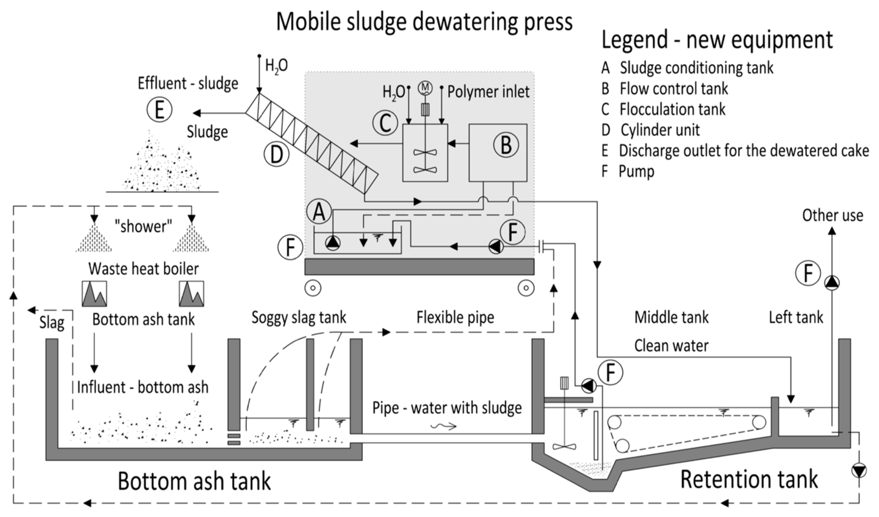
Optimization of the SM system with respect to the technological scheme in
Figure 2 consists in the design of a mobile sludge dewatering press installed on a mobile truck chassis. This mobile system will be transported by the operator as needed between the bottom ash tank and the retention tank. As regards the retention tank, soggy slag together with soggy slag sludge will be extracted from the retention tank by a feed pump placed on a composite platform. The second auxiliary pump will be placed on the mobile system, the discharge pipe will lead to a sludge conditioning tank where other chemicals can be added, and where another pump is installed.
The soggy slag then continues from the third pump to a flow control tank where the amount is regulated and excess slag overflows back to the sludge conditioning tank. This is followed by a flocculation tank where the selected flocculant, polymer is added and soggy slag is mixed with this chemical and forms floc. Soggy slag with the formed flocs enters a cylinder unit, where sludge is instantly thickened in the thickening zone in the previous stage and dewatered at the dewatering zone in the subsequent stage under increasing inner pressure. This is followed by a discharge outlet for the dewatered cake, extra pressure is applied from the outlet side with the end plate, and the discharged dewatered cake has solids content of 15% or higher.
Sludge then overflows to a container and is processed by the operator together with slag from the bottom ash tank. The filtrate, treated water from the mobile dewatering press, is discharged into the left tank and is intended for re-use in SAKO Brno, a.s. area, for example, for lime milk dilution.
4. Discussion
Selected pollution parameters according to the performed analyses of soggy sediments from the retention tank confirmed the impossibility of discharging WW into the sewerage system in accordance with the sewerage regulations. Construction of a WWTP including processes of neutralization, precipitation, evaporation and sludge disposal entails high financial demands on investments and operation. The current method of cleaning the soggy slag tank and the retention tank with a sludge volume disposed of by an external specialized company in the amount of about 50 m3 per month is financially demanding in operational terms.
Based on the expected proposal of sludge thickening technology: chamber filter press, sludge dewatering press and belt filter press, the sludge dewatering press was selected for pilot testing. The sludge dewatering press pilot unit was tested in real conditions with the application of two types of flocculants. Optimal flocculation was achieved only periodically at times when the sludge concentration was temporarily stable.
The efficacy of coagulation and flocculation (called in some literature as sludge conditioning) is, to a large extent, dependent on pH. Upstream coagulation, pH adjustment is usually included in the process line. By using proposed polymers YESfloc the proposed sludge treatment process at the MSWI does not require any additional high pH adjustment (around pH 12). By maintaining the current pH value, the metal compounds remain in insoluble form, which subsequently improves the quality of filtrate and increases dewatering efficiency.
With regard to unstable operating conditions and variation in input sludge concentrations, laboratory tests of the flocculants were conducted. Test was conducted on 500 mL of a representative sample using several flocculants and including their combinations. For the laboratory evaluation of the efficiency of soggy slag representative sample dewatering, a methodology for the evaluation of dewatering efficiency using categories C1 to C4 was applied. Based on the results of the efficient separation testing, a combination of the following Polymers: coagulant YESfloc PA 100 and flocculant YESfloc AWE35, following by YESfloc CWE35. The resulting products are sediment and filtrate, both these products can be processed by the MSWI plant. A proposal was made to optimize the SM.
The SM was optimized using a mobile sludge dewatering press installed on a mobile chassis. These mobile systems will be moved around by the operator as needed between the bottom ash tank and the retention tank. The resulting sludge will be processed by the operator together with slag from the bottom ash tank. The filtrate, treated water from the mobile dewatering press, will be fed to the left tank and will be further reused, for example, to dilute lime milk.
5. Conclusions
The applied research has shown that is not necessary to install a stationary WWTP at MSWI SAKO Brno to treat WW in order to meet the sewerage regulation parameters. Furthermore, it has been determined that there is no need to install a chamber press or belt press meeting the high demand for dry solids content in DW. As an optimum solution, a mobile sludge dewatering press unit has been proposed with a suitable flocculant combination which makes the SM with the proposed optimization a waste-free system without the necessity to carry out laborious and costly bottom ash tank and retention tank cleaning. These results can be transferred into optimizing ST of others MSWIs. Current research is focused on performing further flocculant tests for optimal combination of dewatering.


