1. Introduction
Pipe failure in drinking water distribution networks occurs as a result of high loadings on the pipe. Especially, pipes that deteriorate over time have an increasing probability of failure. Prediction models that estimate when a particular pipe will fail are therefore valuable tools in pipe replacement strategies.
Comsima (COMputation of Stresses In MAins) is a numerical model that predicts the pipe stresses and joint rotations as a result of different loadings on the pipe [
1,
2]. The model follows as much as possible physical principles to predict pipe failure. Failure occurs when the stresses or rotations exceed the maximum allowable values.
In this paper, the basics of Comsima are explained including pipe degradation mechanism for AC and PVC pipes. By adding degradation mechanisms to Comsima, the evolution of pipe stresses and joint rotations over time can be approximated, as well as the progressive changes in allowable pipe stresses, allowing for prediction of the life expectancy of pipes. Furthermore, a more detailed approximation of soil differential settlements was added by means of high resolution satellite data (PS-InSAR). The satellites measure the soil deformation in time (mm/year) at a large number of spatial positions. These positions are transformed to the individual pipes in the network to obtain the differential settlement rate along the pipe (in mm/year). Model validation was conducted by comparing predicted pipe failures with pipe failure registrations for an area in the Netherlands (30 × 50 km).
2. Materials and Methods
2.1. Comsima
Comsima uses a numerical model to calculate stresses and joint rotation in a pipe. The following loadings are incorporated: differential soil settlement, internal water pressure, soil loading and traffic loading. The different loading result in stresses in different directions. From these stresses, the Von Mises stress is calculated, which are compared to the maximum allowable stress. Differential soil settlements result in bending stresses but also in joint rotation. Joint rotation depends on the stiffness of the soil, bending stiffness of the pipe and soil settlement curve. Hereby it is assumed that the joints have zero stiffness. More details are explained in Wols et al. [
1,
2,
3].
Both the stresses and rotations are compared to the allowable stresses (
) and rotations (
), which result in a failure parameter:
If the failure parameter exceeds 1, pipe failure will occur.
2.2. Pipe Degradation Mechanisms
Reduction of wall thickness by leaching of calcium (asbestos-cement) and slow crack growth resistance (PVC) were considered as pipe degradation mechanisms. For the reduction of wall thickness in AC pipes, knowledge rules that were previous developed for AC pipes in the Netherlands were used [
4]. In these knowledge rules, both internal and external leaching were considered. For internal leaching, the saturation index of the water is used [
4]:
SI > 0, wall thickness reduction = 0 mm/year;
−0.2 < SI < 0, wall thickness reduction = 0.05 mm/year;
−0.8 < SI < −0.2, wall thickness reduction = 0.1 mm/year;
SI < −0.8, wall thickness reduction = 0.2 mm/year.
External leaching may occur for pipes without external coating. The external leaching depends on the concentration of calcium carbonate in the soil [
4]:
CaCO3 > 1%, wall thickness reduction = 0.0 mm/year;
0.5% < CaCO3 <1%, wall thickness reduction = 0.05 mm/year;
CaCO3 < 0.5%, wall thickness reduction = 0.1 mm/year.
For PVC pipes, the stress over time as a result of slow crack growth resistance can be written as derived from [
5]:
where
σf represents the allowable stress over a time
t,
σfb is the initial allowable stress and
σfa the reduction in allowable stress. In the knowledge rules, the value of
= −3.5 MPa/log(s) is used corresponding to the design guidelines for PVC (allowable stress of 42 MPa at 1 h and 35 MPa at 100 h [
5]). The initial allowable stress is determined as follows using an artifical lifetime (LT) [
4]:
where
LTmax = 300 years and
LTmin = 35 years. The score depends on the year of installation, as the quality of the installed pipes has been different over the years: the score is 0.9 for years of installation <1970, 0.5 for years of installations between 1970 and 1980, and 1.0 for years of installation >1980.
The soil (differential) settlements can also change over time. Using the satellite data, the soil settlement is measured over time on fixed scatter points at the earth surface to obtain the soil settlement rate (mm/year) [
6]. These points are translated to the pipes: each pipe is divided into segments of 5 m, and for each segment the scatter points that are within a buffer of 10 m are taken, from which an average soil settlement rate is obtained (weighted by the distance to the center of the pipe).
2.3. Case Study in the Netherlands
In a case study, Comsima calculations were made for a water distribution network in an area in the Netherlands (30 × 50 km) and compared to pipe failure registrations. The following data is used for the Comsima calculation:
pipe data (shapefile format used in a geographical information system (GIS)), consisting of: material (including PVC pressure class), diameter, original wall thickness, year of installation, internal pressure (maximum pressure on an average day calculated from a hydraulic model Synergee), internal and external coating, status (in operation or not in operation), date of latest change in status;
satellite data, obtained from SkyGeo for the considered area in the Netherlands;
drinking water quality data: saturation index and corrosion index;
data of surroundings: soil types (using soil type map 2006 [
7]) lime content in soil (using Alterra soil map [
8]), ground water levels (using Alterra soil map [
8]) location of roads and road classes (using TOP10NL [
9]).
Failure data over the period 2009–2017 was gathered from USTORE (a Dutch failure registration database [
10]). Both failures in pipes and joints were considered. Failures caused by third parties or by installation errors were removed. This results in 983 failures in AC pipes on a total length of 2150 km and 198 failures in PVC pipes on a total length of 922 km.
3. Results of Case Study
3.1. Results of Comisma
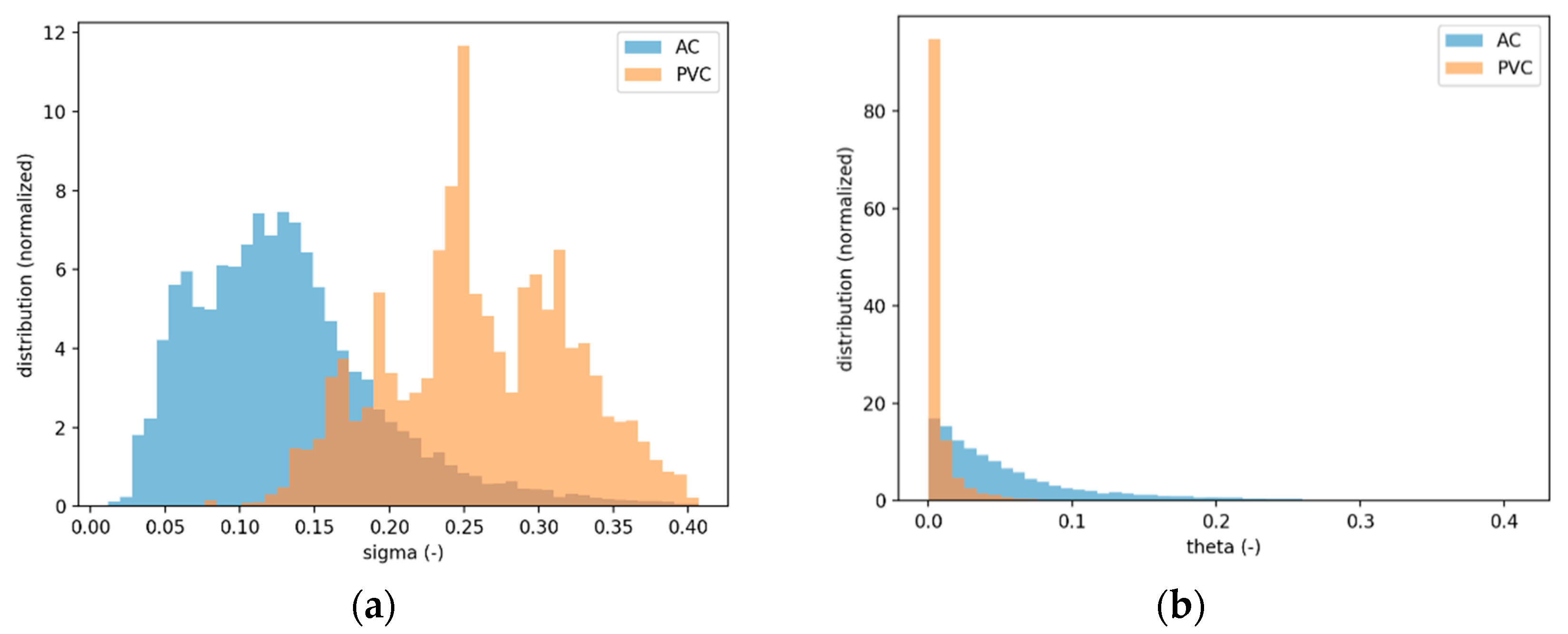
Comsima calculated the normalized stresses and normalized joint rotations in each pipe (
Figure 1). The maximum value of the normalized stress and normalized joint rotation of each pipe is described by the failure parameter. The failure parameter is largely defined by the stresses, as the normalized stresses are usually higher than the normalized joint rotations. In general the stresses are low: for AC pipes, the stresses are mostly below 30–40% of the allowable material stress with a peak at around 10%. In PVC pipes the stresses are a little higher with a peak of around 20–30% of the allowable material stress.
Figure 2 shows the percentage decrease in wall thickness as a result of ageing. Most of the AC pipes have a reduced wall thickness between 20 and 50% of the original wall thickness. A pipe with reduced wall thickness results in an increase in stress, shown by the failure parameter in
Figure 2 with and without ageing. Although the stress may increase with a factor of 2 (depending on the wall thickness reduction), the increase in terms of allowable stress is small (around 5% of the allowable stress).
3.2. Comparison with Failure Data
The calculated failure parameter from Comsima is compared to the failure rate from failures registrations (
Figure 3). Each point in the figure represents a pipe material cohort with a certain failure parameter range. The failure rate is determined by counting the number of failures in each cohort divided by the period of the failure registration and the total length valid for each cohort (determined from the pipes with the considered pipe material and within the Comsima calculated failure parameter range). The AC pipes show a clear relation (
Figure 3): a higher value of the failure parameter results in a higher failure rate. The PVC pipes do not show a clear relation with the failure parameter. When only joint rotations are considered (
Figure 3c), although the joint rotation in terms of allowable rotation is small, the failure rate does increase with a higher joint rotation.
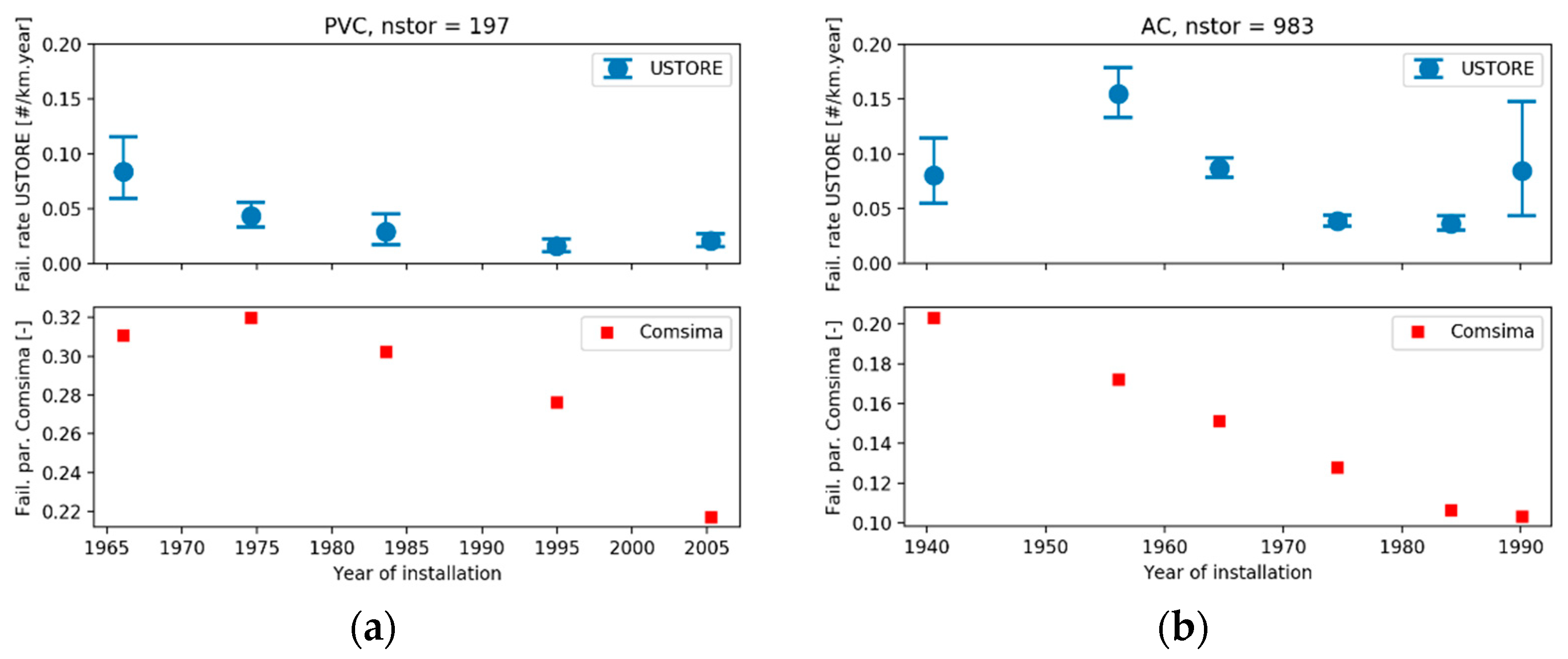
In addition, cohorts were constructed upon pipe material and pipe age (with installation year categories of 10 years, and 25 years for pipes constructed before 1950). Failure rates from failure registrations as well as the Comsima failure parameter were plotted against the year of installation (
Figure 4). Both Comsima and the failure registration show an increase in pipe failure with increasing pipe age.
4. Discussion
Despite of some deviations, the Comsima results in general show similar trends as the failure registration. One of these deviations is the relation between pipe stresses and failures in PVC. This may be caused by the variations in allowable stresses that are found in samples of PVC pipes [
11] and the complexity of the PVC ageing process. In the current model, the reduction in allowable stress is an exponential function of time, resulting in an allowable stress after 100 years that varies between 20 and 21 MPa (depending on the year of installation). However, in reality the loadings are not constant in time (e.g., traffic loads, increasing differential settlement) and ageing is a complex process often depending on local stresses around impurities in the material, so that much more variation in allowable stresses can be expected.
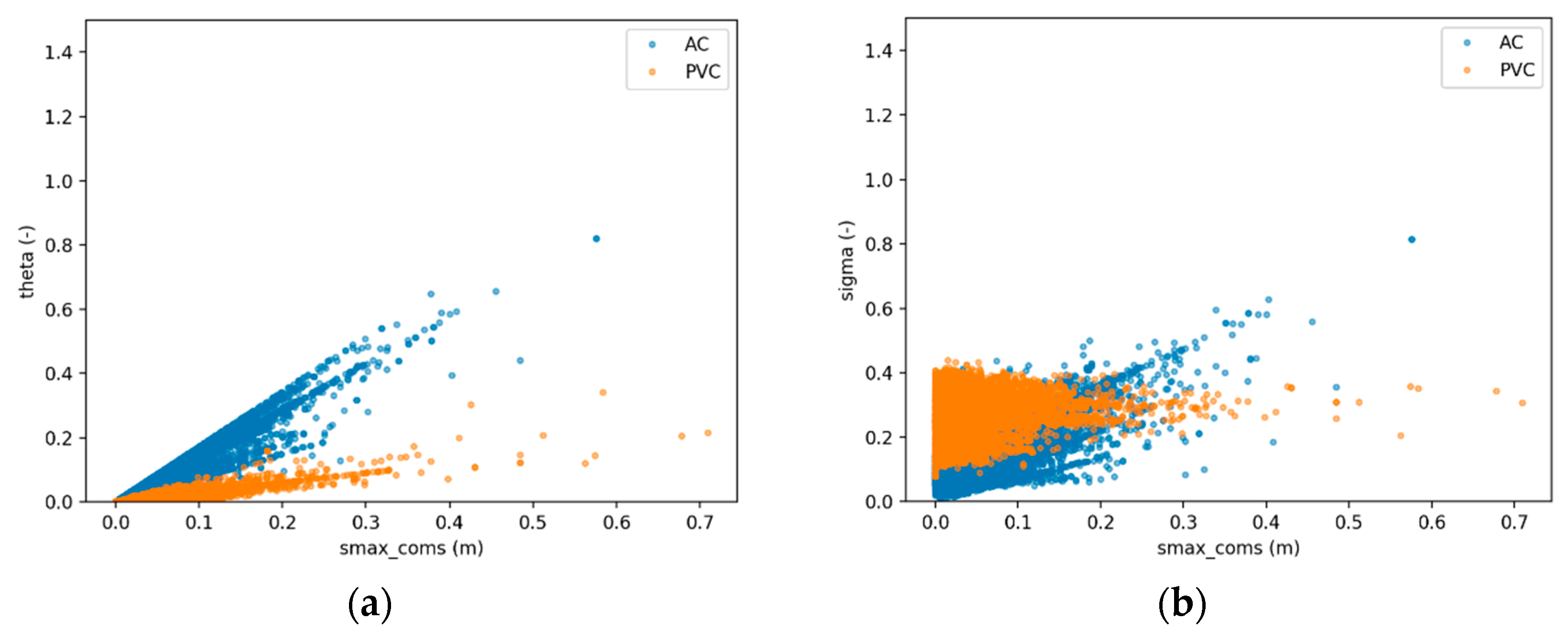
In addition, the effect of (differential) settlement may partly be underestimated. The differential settlement from the satellite data is plotted against the calculated pipe stresses and joint rotations (
Figure 5). For AC, a distinct relation between both Comsima results and the settlement can be found. However, for PVC there is no increase in pipe stresses and a small increase in joint rotation at higher settlements. The calculated joint rotation remains small compared to the allowable joint rotation. As PVC pipes are more flexible, a part of the settlement is taken up by bending of the pipe and another part by joint rotation. But due to the low elasticity modulus the bending of the pipe does not result in much higher stresses. So, according to the model, PVC is not sensitive to differential settlements. Nevertheless, from the failure registration, it can be observed that both AC and PVC show a significant higher failure rate in pipes with larger differential settlements (
Table 1). Possibly other failure mechanisms, and the complex interaction between joint and failure may explain these deviations. Finite element modelling (FEM) is therefore conducted [
12], which results in allowable joint rotations that could be included in Comsima.
5. Conclusions
Comsima is a mechanical model that calculates stresses and joint rotations in drinking water distribution pipes based upon several loadings on the pipe (soil, traffic, water pressure, differential settlements). Pipe degradation mechanisms (slow crack growth resistance for PVC and calcium leaching for AC) were added to the model. A comparison with failure registration for an area in the Netherlands using satellite data to determine differential settlements show that pipes with higher stresses or higher joint rotations in general have a higher failure rate.
Several improvements are being developed to further increase the accuracy of the predictions of Comsima. Amongst them are improvements of pipe degradation mechanism and the inclusion of more advanced modelling techniques, such as FEM (finite-element models) to determine allowable PVC joint rotations [
12]. Data from inspection techniques could also help to improve degradation models. In addition, also a Monte Carlo method could be applied in Comsima to allow for variations in input parameters. However, the variations in terms of probability density functions needs to be carefully chosen and justified, preferably on actual data. Results from the Monte Carlo analysis could then be used for a better translation of the Comsima results with failure rates, for example using the concept of hazard rate as a function of pipe age.
Author Contributions
B.W. developed the model and wrote the paper; A.M. performed the GIS analyses, P.H. provided the data and contributed to the data preparation, K.v.L. contributed to the ageing mechanisms of the model.
Funding
This study was funded by the Dutch drinking water company PWN as well as the Dutch drinking water companies within the context of the BTO collective research program of the Dutch drinking water sector.
Conflicts of Interest
The authors declare no conflict of interest. The funding sponsors provided data and agreed on publishing the results.
References
- Wols, B.A.; van Thienen, P. Modelling the effect of climate change induced soil settling on drinking water distribution pipes. Comput. Geotech. 2014, 55, 240–247. [Google Scholar] [CrossRef]
- Wols, B.A.; van Thienen, P. Modelling the effect of climate change induced soil settling on jointed drinking water distribution pipes. Comput. Geotech. 2015, 70, 106–115. [Google Scholar] [CrossRef]
- Wols, B.A.; van Daal, K.; van Thienen, P. Effects of climate change on drinking water distribution network integrity: Predicting pipe failure resulting from differential soil settlement. Procedia Eng. 2014, 70, 1726–1734. [Google Scholar] [CrossRef]
- Beuken, R.H.S.; Mesman, G.A.M. Kennissysteem Levensduurbepaling Versie 2.0, (‘Knowledge system lifetime determination version 2.0′) BTO 2011.113(s); KWR Watercycle Research Institute: Nieuwegein, The Netherlands, 2011. [Google Scholar]
- NEN-EN-ISO 1452-1:2009; Plastics Piping Systems for Water Supply and for Buried and above-Ground Drainage and Sewerage under Pressure—Unplasticized Poly(Vinyl Chloride) (PVC-U). NEN: Delft, The Netherlands, 2009.
- Tabak, A.; Maljaars, H. Memo: Beknopte Uitleg Kaartlagen InSAR Analyse; SkyGeo: Delft, The Netherlands, 2017. [Google Scholar]
- Grondsoortenkaart 2006. Available online: http://www.wageningenur.nl/nl/show/Grondsoorten kaart.htm (accessed on 1 June 2016).
- Bodemkaart 2006. Available online: http://www.wageningenur.nl/nl/show/Bodemkaart-1-50-000.htm (accessed on 1 June 2016).
- TOP10NL 2016. Available online: http://www.kadaster.nl/web/artikel/producten/TOP10NL.htm (accessed on 1 June 2016).
- Vreeburg, J.H.G.; Vloerbergh, I.N.; van Thienen, P.; de Bont, R. Shared failure data for strategic asset management. Water Sci. Technol. Water Supply 2013, 13, 1154–1160. [Google Scholar] [CrossRef]
- Mesman, G. Kennisregels PVC Leidingen (‘Knowledge Rules PVC Pipes’); BTO 2015.054; KWR Watercycle Research Institute: Nieuwegein, The Netherlands, 2015. [Google Scholar]
- Van Laahoven, K.; Wols, B.A. Combining models to simulate the condition of the PVC distribution network. In Proceedings of the 3rd EWaS International Conference on “Insights on the Water-Energy-Food Nexus”, Lefkada, Greece, 27–30 June 2018. [Google Scholar]
| Publisher’s Note: MDPI stays neutral with regard to jurisdictional claims in published maps and institutional affiliations. |
© 2018 by the authors. Licensee MDPI, Basel, Switzerland. This article is an open access article distributed under the terms and conditions of the Creative Commons Attribution (CC BY) license (https://creativecommons.org/licenses/by/4.0/).


