Mixing of Particles in Micromixers under Different Angles and Velocities of the Incoming Water †


Abstract
:1. Introduction
2. Materials and Methods
3. Results
4. Conclusions
References
- Foley, J.A.; De Fries, R.; Anser, G.P.; Barford, C.; Bonan, G.; Carpenter, S.R.; Chapin, F.S.; Coe, M.T.; Daily, G.C.; Gibbs, H.K.; et al. Global consequences of land use. Science 2005, 309, 570–574. [Google Scholar] [CrossRef] [PubMed]
- Falconer, I.R.; Humpage, A.R. Health risk assessment of cyanobacterial (blue-green algal) toxins in drinking water. J. Environ. Res. Public Health 2005, 2, 43–50. [Google Scholar] [CrossRef] [PubMed]
- Li, F.B.; Li, X.Z.; Liu, C.S.; Liu, T.X. Effect of alumina on photocatalytic activity of iron oxides for bisphenol; A degradation. J. Hazard Mater. 2007, 149, 199–207. [Google Scholar] [CrossRef] [PubMed]
- Daniel-da-Silva, A.L.; Lóio, R.; Lopes-da-Silva, J.A.; Trindade, T.; Goodfellow, B.J.; Gil, A.M. Effects of magnetite nanoparticles in the thermorheological properties of carrageenan hydrogels. J. Colloid Interface Sci. 2008, 324, 205–211. [Google Scholar] [PubMed]
- Shen, Y.F.; Tang, J.; Nie, Z.H.; Wang, Y.D.; Ren, Y.; Zuo, L. Preparation and application of magnetic Fe3O4 nanoparticles for wastewater purification. Sep. Purif. Technol. 2009, 68, 312–319. [Google Scholar] [CrossRef]
- Indira, T.K.; Lakshmi, P.K. Magnetic nanoparticles—A review. Int. J. Pharm. Sci. Nanotechnol. 2010, 3, 1035–1042. [Google Scholar]
- Qu, X.; Alvarez, P.J.; Li, Q. Applications of nanotechnology in water and wastewater treatment. Water Res. 2013, 47, 3931–3946. [Google Scholar] [CrossRef] [PubMed]
- Karvelas, E.G.; Lampropoulos, N.K.; Karakasidis, T.E.; Sarris, I.E. A computational tool for the estimation of the optimum gradient magnetic field for the magnetic driving of the spherical particles in the process of cleaning water. Desalin. Water Treat. 2017, 99, 27–33. [Google Scholar] [CrossRef]
- Lampropoulos, N.K.; Karvelas, E.G.; Sarris, I.E. Computational Modeling of an MRI Guided Drug Delivery System Based on Magnetic Nanoparticle Aggregations for the Navigation of Paramagnetic Nanocapsules. In Proceedings of the 11th World Congress on Computational Mechanics (WCCMXI) 2014, Barcelona, Spain, 14 April 2015; Available online: https://arxiv.org/abs/1504.03490 (accessed on 19 March 2018).
- Karvelas, E.G.; Lampropoulos, N.K.; Sarris, I.E. A numerical model for aggregations formation and magnetic driving of spherical particles based on OpenFOAM®. Comp. Methods Progr. Biomed. 2017, 142, 21–30. [Google Scholar] [CrossRef] [PubMed]
- Tijskens, E.; Ramon, H.; Baerdemaeker, J. Discrete element modelling for process simulation in agriculture. J. Sound Vib. 2003, 266, 493–514. [Google Scholar] [CrossRef]


| Simulation Parameters | ||
|---|---|---|
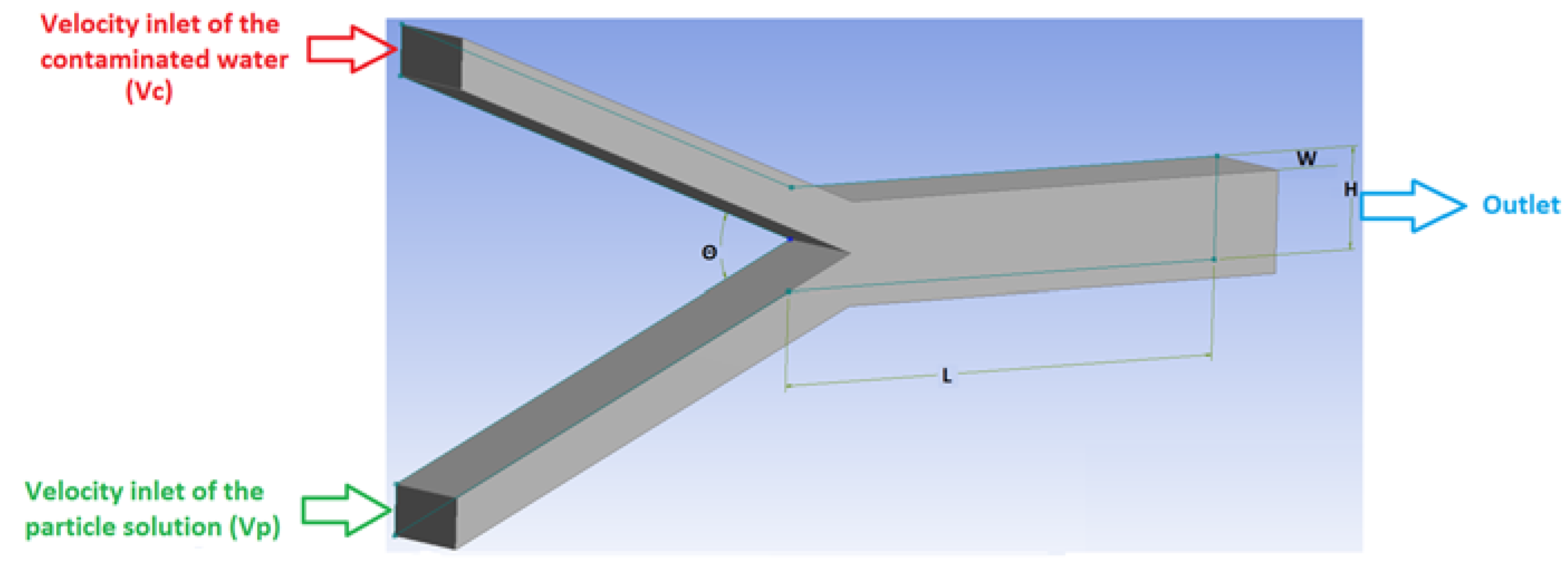
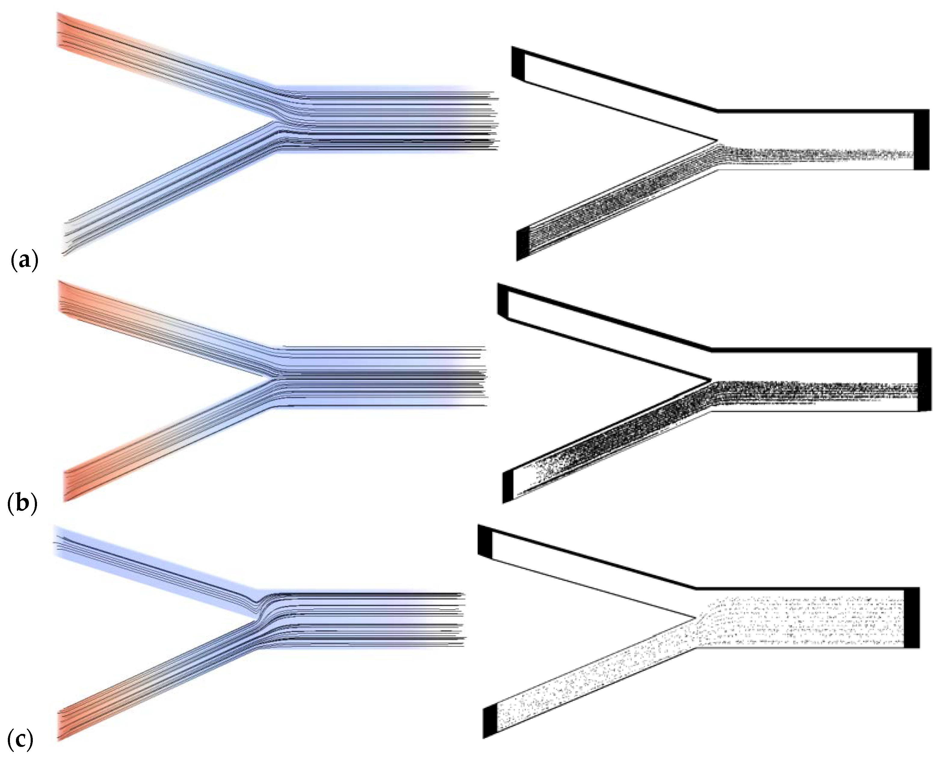
| Dimensions of the micromixer geometry | Length (L): 5 × 10⁻⁴ m, Height (H): 1 × 10⁻⁴ m, Width (W): 1 × 10⁻⁴ m | |
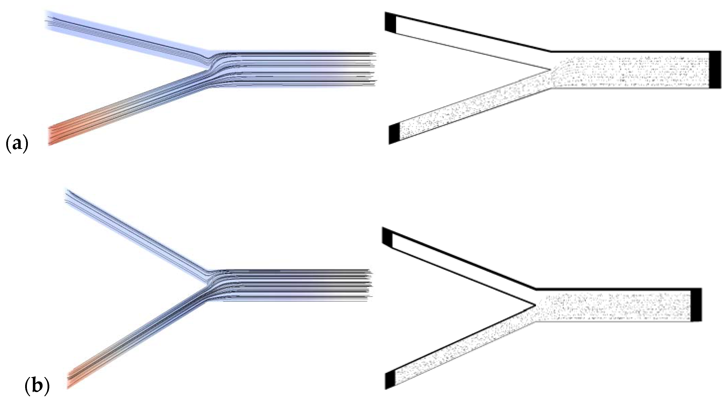
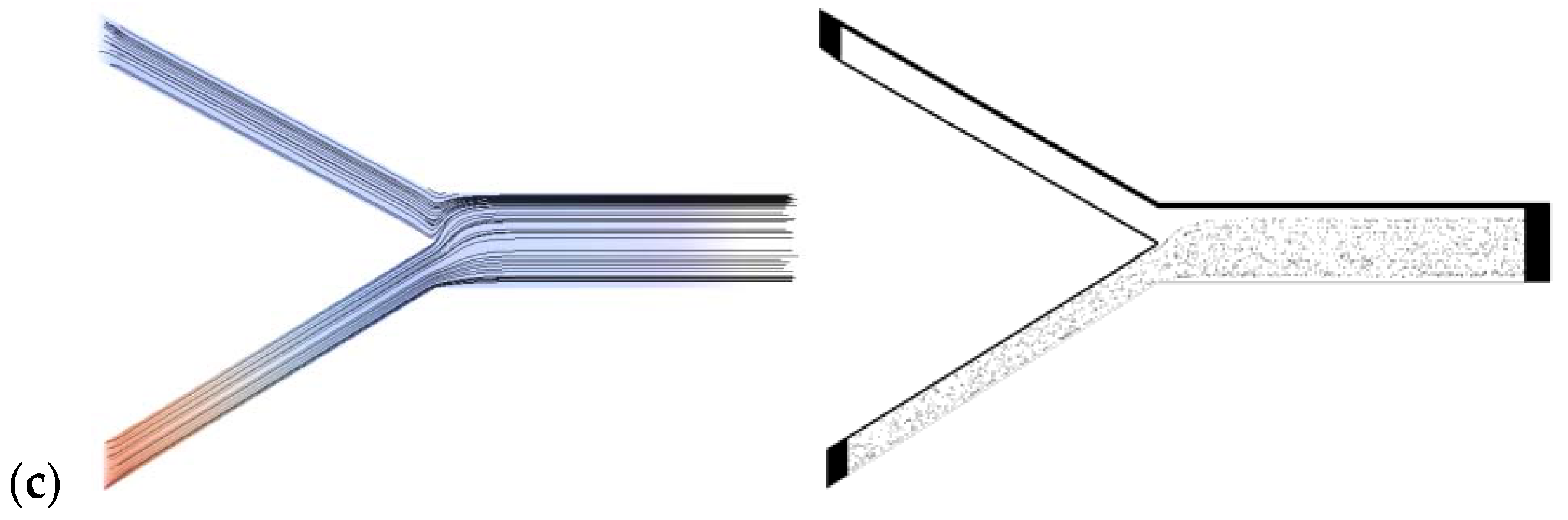
| Inlet angle (Θ) between the two streams | 30°, 45°, 60° | |
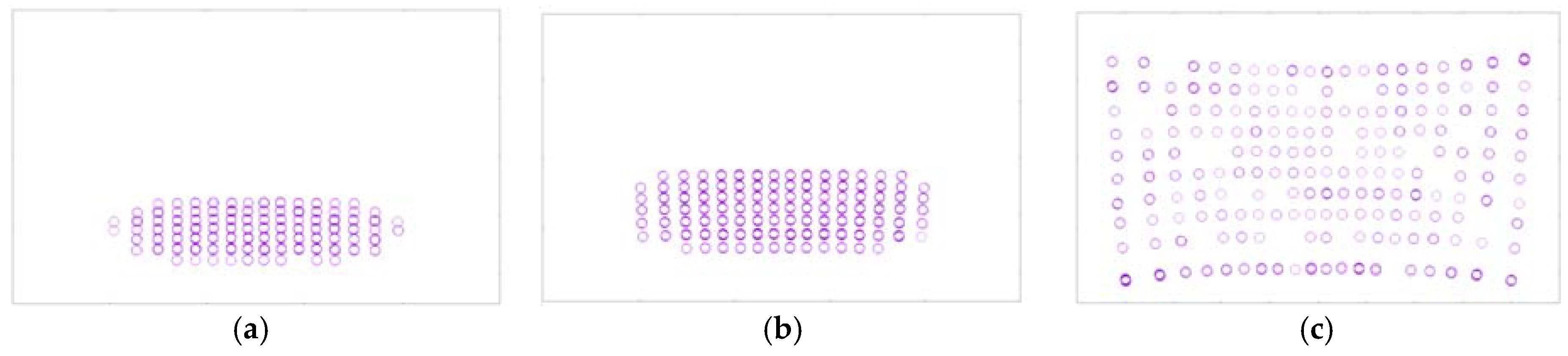
| Diameter of particles | 1 μm | |
| Particles per second | 3000 | |
| Particle’s density | 1087 kg/m3 | |
| Boundary conditions | ||
| Boundary | Velocity (U) (m/s) | Pressure (p) (pa) |
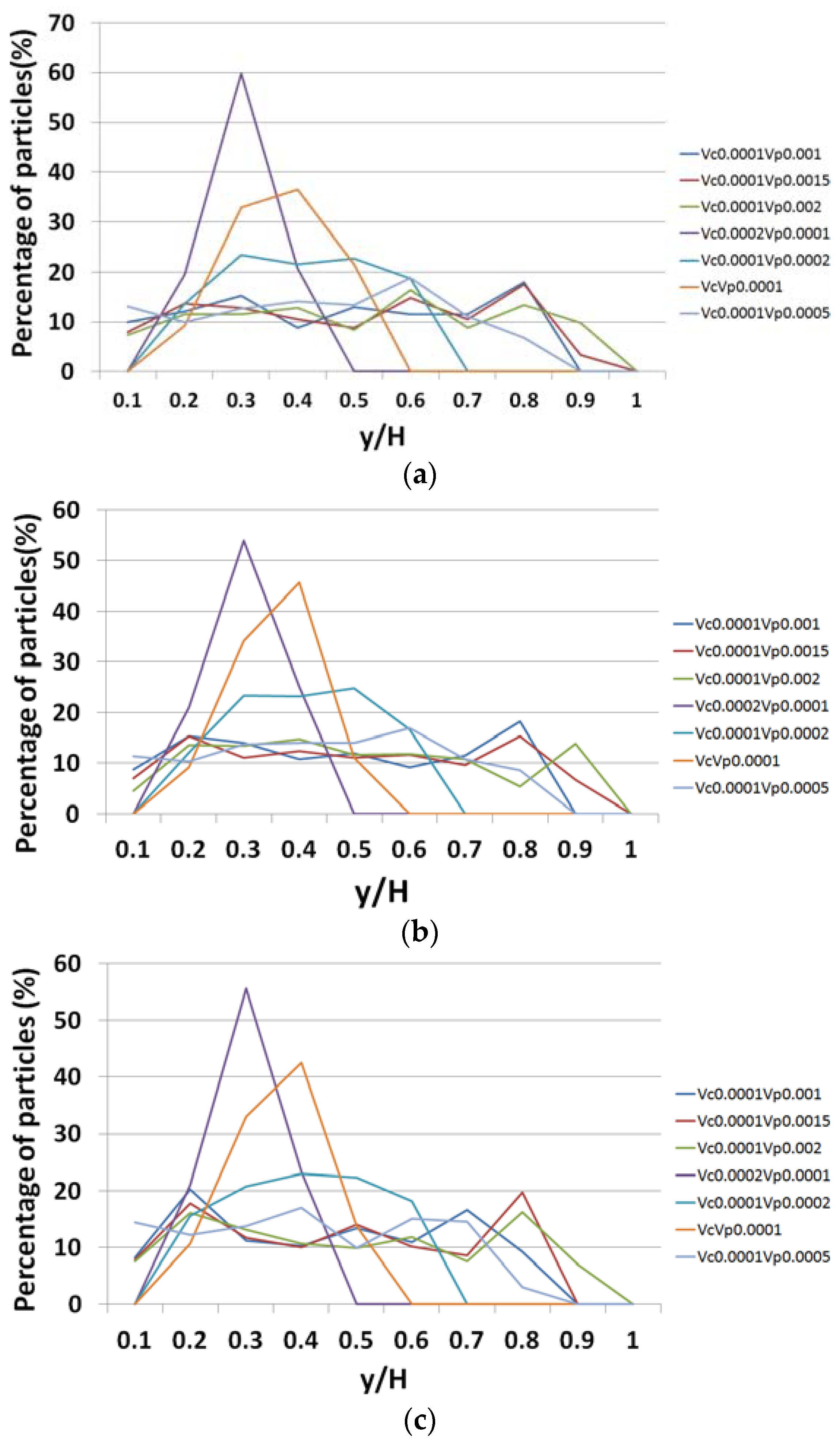
| Contaminated water (Vc) | 0.001, 0.002 | zero gradient |
| Particle solution (Vp) | 0.0001, 0.0002, 0.0005, 0.001, 0.0015, 0.002 | zero gradient |
| Outlet | zero gradient | 0 |
| Walls | 0 | zero gradient |
Publisher’s Note: MDPI stays neutral with regard to jurisdictional claims in published maps and institutional affiliations. |
© 2018 by the authors. Licensee MDPI, Basel, Switzerland. This article is an open access article distributed under the terms and conditions of the Creative Commons Attribution (CC BY) license (https://creativecommons.org/licenses/by/4.0/).
Share and Cite
Karvelas, E.; Liosis, C.; Karakasidis, T.; Sarris, I. Mixing of Particles in Micromixers under Different Angles and Velocities of the Incoming Water. Proceedings 2018, 2, 577. https://doi.org/10.3390/proceedings2110577
Karvelas E, Liosis C, Karakasidis T, Sarris I. Mixing of Particles in Micromixers under Different Angles and Velocities of the Incoming Water. Proceedings. 2018; 2(11):577. https://doi.org/10.3390/proceedings2110577
Chicago/Turabian StyleKarvelas, Evangelos, Christos Liosis, Theodoros Karakasidis, and Ioannis Sarris. 2018. "Mixing of Particles in Micromixers under Different Angles and Velocities of the Incoming Water" Proceedings 2, no. 11: 577. https://doi.org/10.3390/proceedings2110577
APA StyleKarvelas, E., Liosis, C., Karakasidis, T., & Sarris, I. (2018). Mixing of Particles in Micromixers under Different Angles and Velocities of the Incoming Water. Proceedings, 2(11), 577. https://doi.org/10.3390/proceedings2110577