Abstract
A new millimetre-wave passive and chipless packaged sensor for wireless pressure monitoring in harsh environment is proposed. This sensor uses a planar microstrip resonator coupled with a high resistivity silicon membrane. The remote interrogation of this sensor is performed from a Frequency-Modulated Continuous-Wave (FMCW) radar. Prototypes have been designed and fabricated using photoresist intermediate layer for the silicon membrane bonding. Pressure characterization of packaged sensor validate the transducer and packaging hermeticity. The sensor sensitivity is close to 2% per bar for the resonant frequency and the radar response is evaluated at 2 dB per bar.
1. Introduction
Wireless, batteryless and chipless (without electronic circuit) sensors are a promising solution for the remote measurement of physical quantities in high radiation or extreme temperature environment or/and when the battery replacement is difficult or induces high costs. Electromagnetic sensors operating at millimetre-wave frequency range are good candidates and the authors have demonstrated the proof-of-concept from several transducers [1] using Frequency-Modulated Continuous-Wave (FMCW) radar interrogation [2]. A reading range up to 58 m of passive humidity sensors using a FMCW radar beam scanning technique was recently reported in [3]. This range is significantly higher than one achieved from wireless interrogation of passive RFID sensors (typically lower than 10 m).
In this communication, the authors focus on a practical application case in which pressure is monitored in harsh environment. The objective is to validate a packaged transducer that fits the pressure specification (≅1.4 bar of overpressure) and operates in the frequency range of our FMCW radar (22.8 GHz/24.8 GHz).
In our previous studies, we used a coplanar waveguide (CPW) microwave resonator whose resonant frequency was modified by the displacement of a silicon membrane [4]. However, this configuration required a CPW-to-microstrip line transition (Figure 1) which creates undesirable spurious modes (Figure 2).
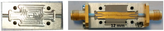
Figure 1.
View of microstrip-to-CPW transition inside the packaging (right) and packaging cover (left).
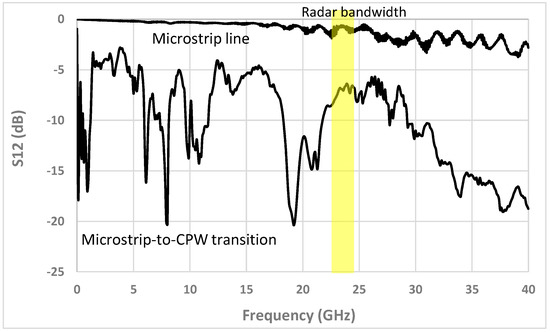
Figure 2.
Measured transmission coefficient (S12) versus frequency by using (1) the microstrip-to-CPW transtion and (2) the microstrip line, inside the packaged structure.
As shown in Figure 2, by removing this transition we obtain a significant improvement of the transmission coefficient through the back-to-back transition and a suppression of spurious resonances. The connection of one port of the packaged structure to an antenna and of the second port to variable load impedance allows remote interrogation from the FMCW radar. We can see that it is possible to reach a full-scale radar response up to 10 dB (Figure 3).
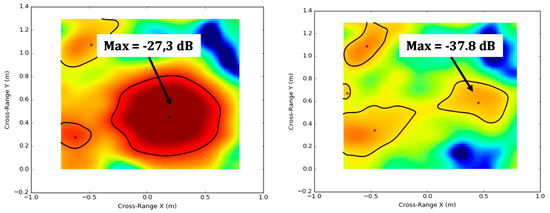
Figure 3.
Cut-planes of a 3D millimeter-wave radar image obtained from a packaged 50 Ω microstrip line loaded by a short-circuit (left) and by the 50 Ω matched impedance (right). The full-scale radar response is of 10dB
2. Design of the Microstrip Resonator
The new design of the transducer with microstrip resonator is shown in Figure 4 and Figure 5. A 0.5 μm thick aluminium layer is used to fabricate a half-wavelength coupled line resonator on a 500 μm thick borosilicate glass wafer. A 100 μm thick high resistivity silicon membrane is then bonded over the resonator using low-loss photoresist (≅10 μm thick). This bonding solution allows a quite simple process providing a sufficient hermeticity for experimentally validating the prototype performances.
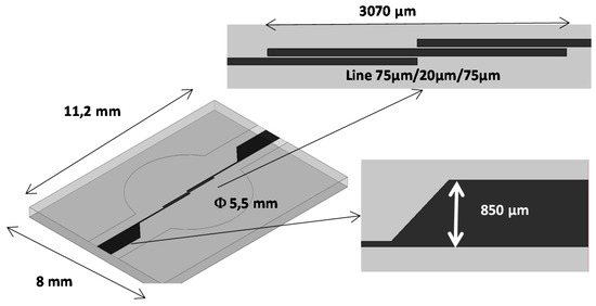
Figure 4.
Dimensions of the microstrip planar resonator.
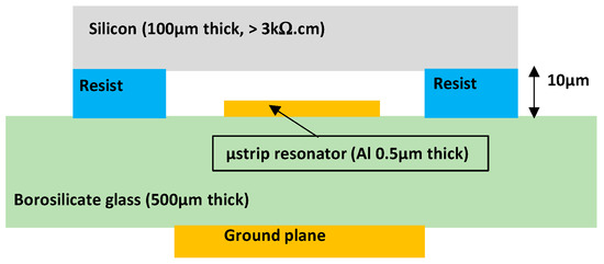
Figure 5.
View of the different sensor layers.
The simulated transducer response is given in Figure 6 where the resonant frequency shift is plotted versus the distance between the silicon membrane and the resonator. The electromagnetic simulation was performed assuming a planar silicon membrane deflection. For the full-scale pressure, a 9 μm membrane deflection is expected leading to a resonant frequency shift of 9%.
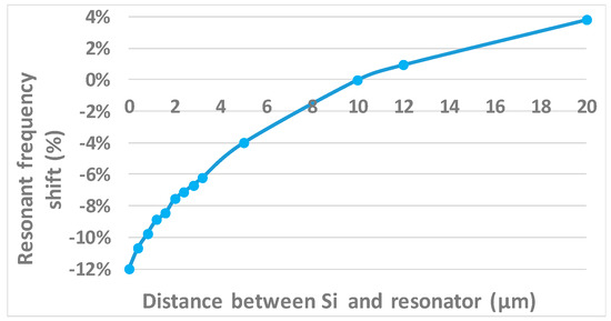
Figure 6.
Simulated resonant frequency shift versus distance between the Si membrane and planar resonator.
3. Characterization of the Sensor
Transducers were fabricated and packaged (Figure 7). In Figure 8 the reflection coefficient S11 is measured for different applied pressures in order to characterize the sensor response. As expected, the resonant frequency decreases when the applied pressure increase (≅2% per bar). For the full scale pressure of 1.4 bar, the total resonant frequency shift is around 0.5 GHz. In Figure 9 the reflection coefficient S11 at the structure input is plotted versus the applied pressure at 23.8 GHz, that is, the frequency at the center of the radar bandwidth. It can observed that the S11 response is quasi-linear with respect to the pressure with a sensitivity of 2 dB per bar. The expected full scale radar response is then of 3 dB. The next steps will be devoted to the indoor and outdoor radar measurements of the sensor.
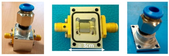
Figure 7.
View of the packaged sensor.
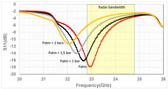
Figure 8.
Measured reflection coefficient S11 versus frequency for various applied overpressure.
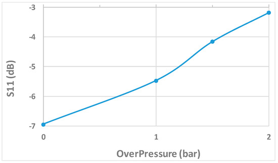
Figure 9.
Measured reflection coefficient S11 at 23.8 GHz versus the applied overpressure.
Acknowledgments
This work was partly supported by the french RENATECH network.
Conflicts of Interest
The authors declare no conflict of interest.
References
- Pons, P.; Aubert, H.; Menini, P.; Tentzeris, M. Electromagnetic transduction for wireless passive sensors. In Proceedings of the Eurosensors 2012, Krakow, Poland, 9–12 September 2012. [Google Scholar]
- Aubert, H.; Chebila, F.; Jatlaoui, M.; Thai, T.; Hallil, H.; Traille, A.; Bouaziz, S.; Rifaï, A.; Pons, P.; Menini, P.; et al. Wireless Sensing and Identification based on RADAR Cross Sections Variability Measurement of Passive Electromagnetic Sensors. Ann. Telecommun. 2013, 68, 425–435. [Google Scholar] [CrossRef]
- Henry, D.; Hester, J.; Aubert, H.; Pons, P.; Tentzeris, M. Long Range Wireless Interrogation of Passive Humidity Sensors using Van-Atta Cross-Polarization Effect and 3D Beam Scanning Analysis. In Proceedings of the IEEE International Microwave Symposium, Honolulu, HI, USA, 4–9 June 2017. [Google Scholar]
- Jatlaoui, M.; Chebila, F.; Pons, P.; Aubert, H. Working Principle Description of the Wireless Passive EM Transduction Pressure Sensor. Eur. Phys. J. Appl. Phys. 2011, 56. [Google Scholar] [CrossRef]
Publisher’s Note: MDPI stays neutral with regard to jurisdictional claims in published maps and institutional affiliations. |
© 2017 by the authors. Licensee MDPI, Basel, Switzerland. This article is an open access article distributed under the terms and conditions of the Creative Commons Attribution (CC BY) license (https://creativecommons.org/licenses/by/4.0/).