Proceeding Paper

MEMS Capacitive Microphone with Dual-Anchored Membrane †

Electronics and Telecommunications Research Institute, Daejeon, Korea
*
Author to whom correspondence should be addressed.
Presented at the Eurosensors 2017 Conference, Paris, France, 3–6 September 2017.
Proceedings 2017, 1(4), 342; https://doi.org/10.3390/proceedings1040342
Published: 9 August 2017
(This article belongs to the Proceedings of Proceedings of Eurosensors 2017, Paris, France, 3–6 September 2017)

Abstract

:
In this paper, we proposed a MEMS capacitive microphone with a dual-anchored membrane. The proposed dual anchor could minimize the deviation of operating characteristics of the membrane according to the fabrication process variation. The membrane is connected and fixed to the back plate insulating silicon nitride structures instead to the sacrificial bottom insulating oxide layer so that its effective size and boundary conditions are not changed according to the process variation. The proposed dual-anchored MEMS microphone is fabricated by the conventional fabrication process without no additional process and mask. It has a sensing membrane of 500 μm diameter, an air gap of 2.0 μm and 12 dual anchors of 15 μm diameter. The resonant frequency and the pull-in voltage of the fabricated device is 36.3 ± 1.3 kHz and 6.55 ± 0.20 V, respectively.

1. Introduction

Recently, MEMS-type capacitive microphones have been widely applied in mobile applications, especially smart phones and tablets [1]. MEMS microphones have been usually fabricated by bulk micromachining processes which include a complicated processes such as multi-layer patterning and bulk etching processes. The deviations of these complicated fabrication processes affect the boundary conditions of the fabricated devices which are important factors of device yield. Sensing membranes of the present MEMS microphones are anchored to the substrate by the remained oxide layer after oxide sacrificial layer etching process [2]. As a results, the membrane anchor position varies according to the fabrication deviations such as back chamber etching and oxide etching profile. To solve this problem, the spring suspended membranes [3,4] and top membrane [5] are employed.
In this paper, we proposed a dual anchor which fixed the membrane to the substrate by using the nitride film constituting the back plate. The silicon nitride film is not affected by the preceding bulk etching processes so that we could fabricate the uniformly anchored sensing membrane. In addition, the proposed dual-anchor structure doesn’t require additional mask layers or fabrication processes.

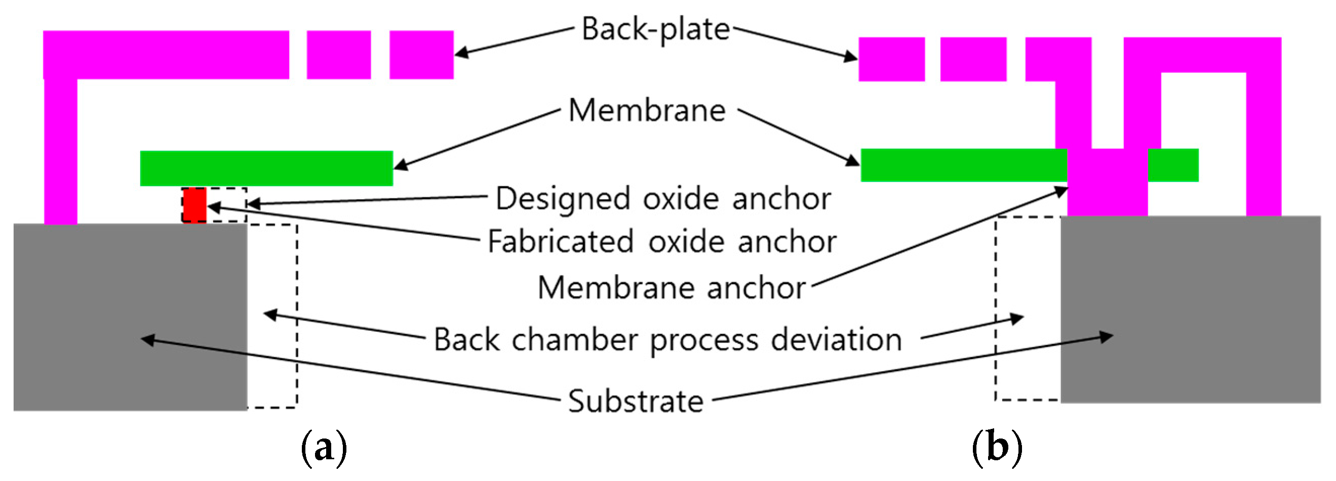
2. Theoretical Analysis

Figure 2a shows a cross-sectional view of the conventional oxide anchored membrane MEMS microphone. The remained insulating oxide layer after sacrificial oxide removal process between the membrane and the substrate acts as an anchor for the sensing membrane. Therefore, the size and position of the anchor is defined by the oxide etching process. Figure 2a shows the relation between the back chamber etching variation and the oxide anchor shape. Table 1 shows the dimensional variations due to the bulk etching process such as substrate through etching for back chamber using Deep Reactive Ion Etcher (DRIE) and sacrificial oxide removal by isotropic etching using Vapor Phase oxide Etcher (VPE). A ±2% deviation of the membrane diameter results a 3.9% to –4.1% deviations of resonant frequency and stiffness of the membrane. And it also affects the pull-in voltage, resulting 4.1% to –3.8% deviations. In this paper, we proposed a dual anchored membrane that are not affected by the fabrication variation. Figure 2b shows the concept of the dual anchor structure. Instead of the previous oxide anchor, the part of the back-plate silicon nitride layer is used as a membrane anchor. It penetrates the edge of the membrane and fixed to the substrate. Therefore, it is not affected by the bulk etching process such as back chamber formation and sacrificial oxide removal as shown in Figure 2b. The simulation results according to the process deviation are summarized in Table 1.

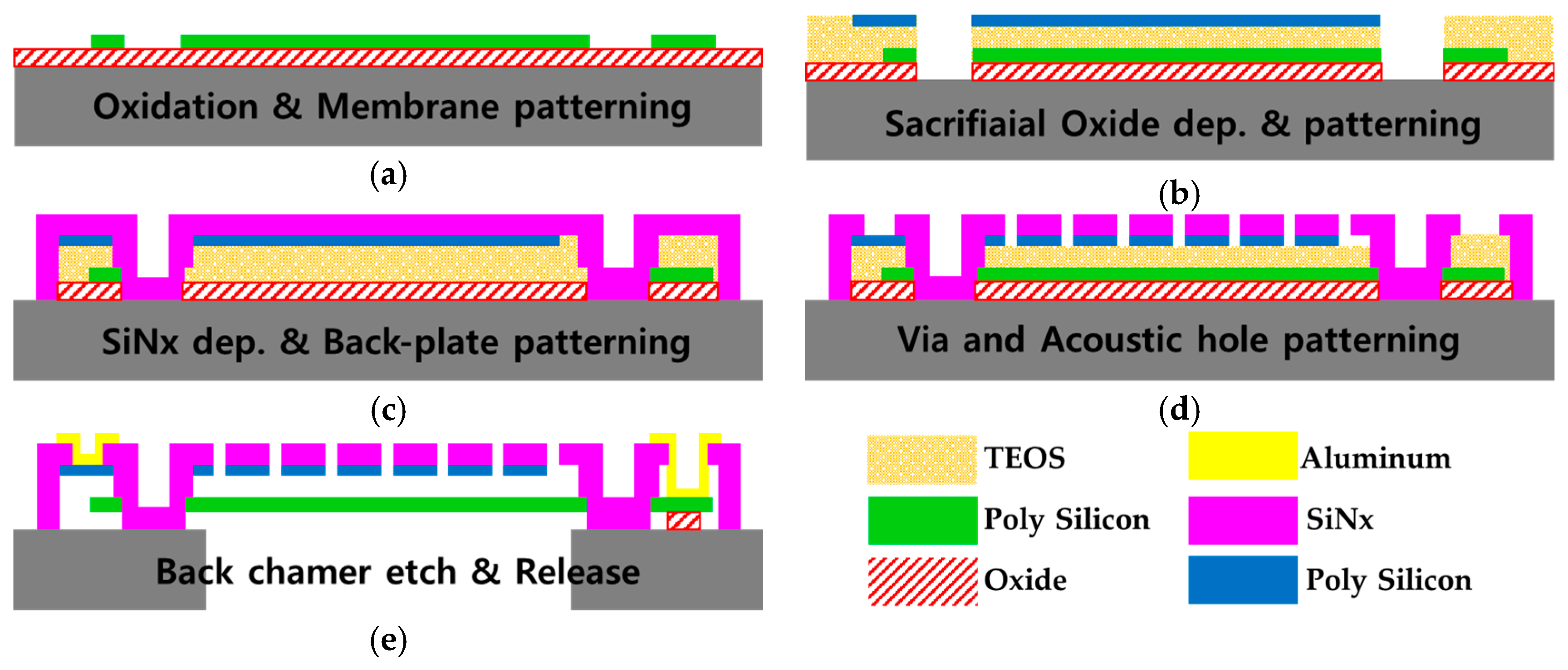
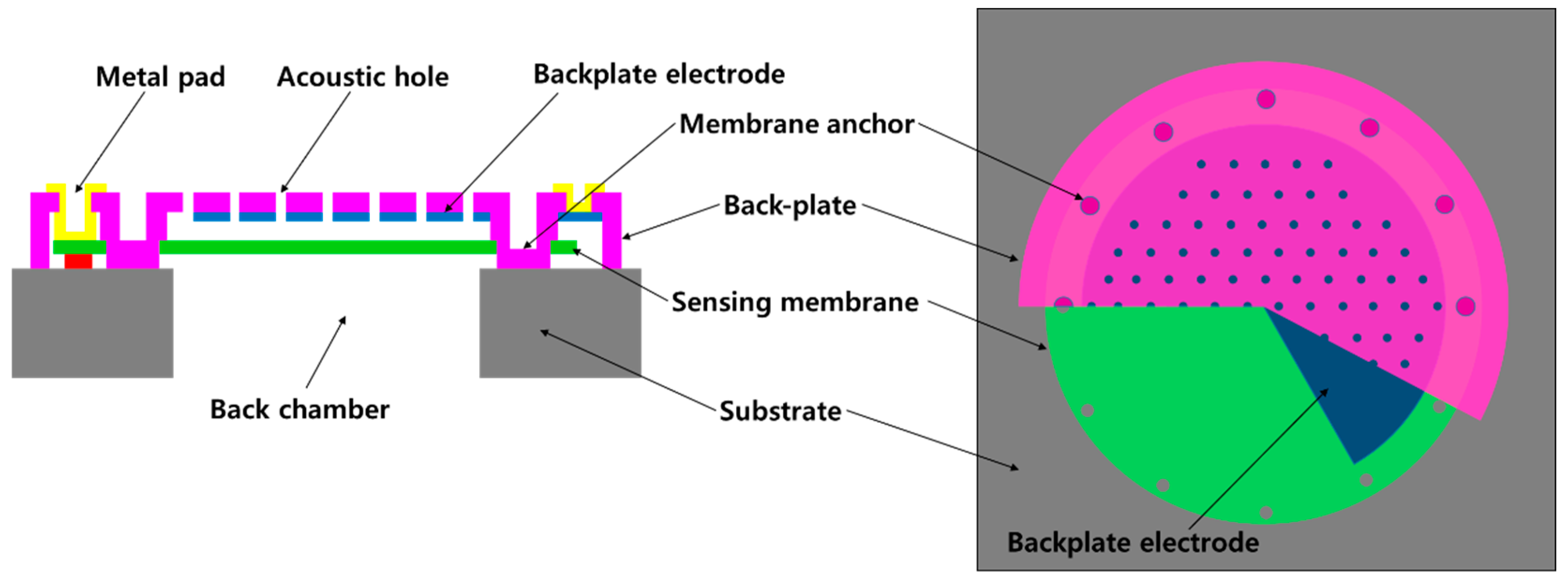
3. Device Design and Fabrication

The proposed dual anchored membrane shows a relatively low stiffness compared to the fully clamped oxide anchored membrane due to its small footprint. So we determined the design parameters to achieve the proper operating characteristics. There are 12 dual anchors are arranged at intervals of 30 degrees on the edge of the membrane. It is a nitride film having a diameter of 15 μm and a thickness of 2.0 μm. Figure 1 shows the schematic view of the proposed MEMS microphone. The design parameters of the proposed dual anchored MEMS microphone are shown in Table 2.
The proposed dual anchor structure is fabricated by using conventional MEMS microphone fabrication process for the oxide sacrificial layer. Especially, it does not require additional materials or fabrication processes or photomasks. It could be fabricated by simply adding patterns to the existing mask layers. The anchor through-hole patterns on the membrane layer and the sacrificial layer are added. Figure 3 shows the fabrication process of the proposed dual anchored MEMS microphone. Figure 4 shows the microscope images of the fabricated MEMS microphone and enlarged view of the dual anchor.

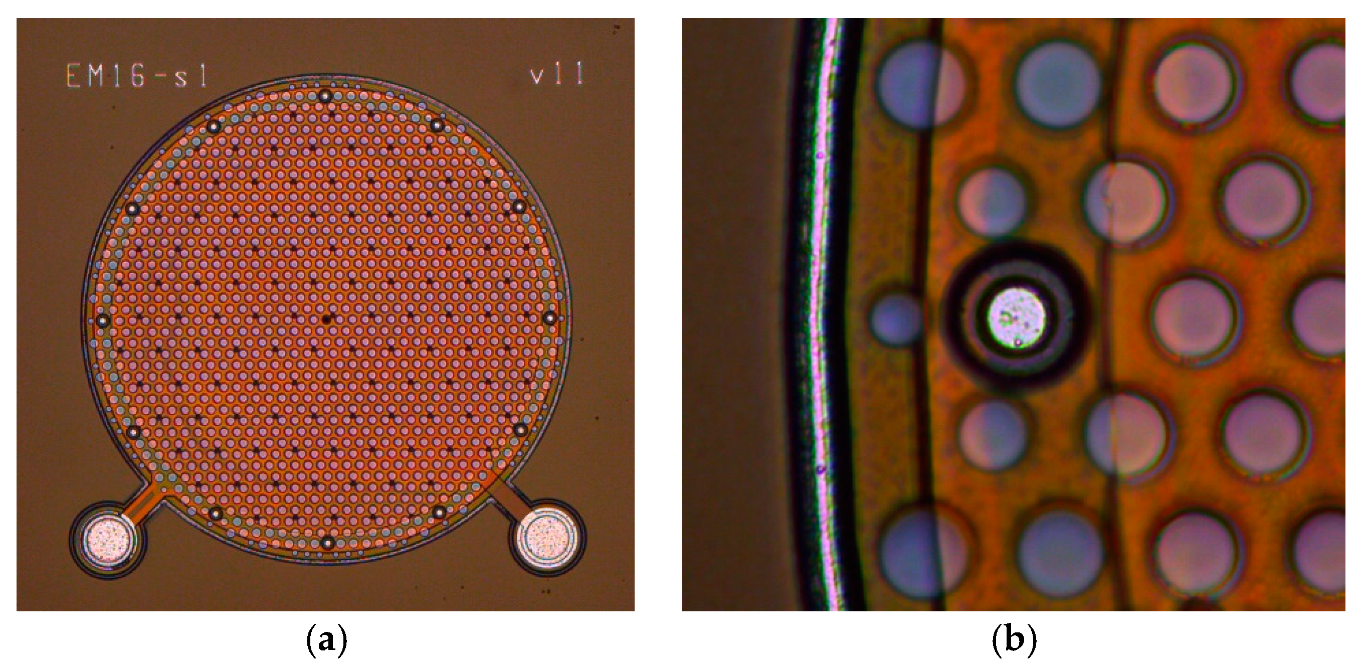
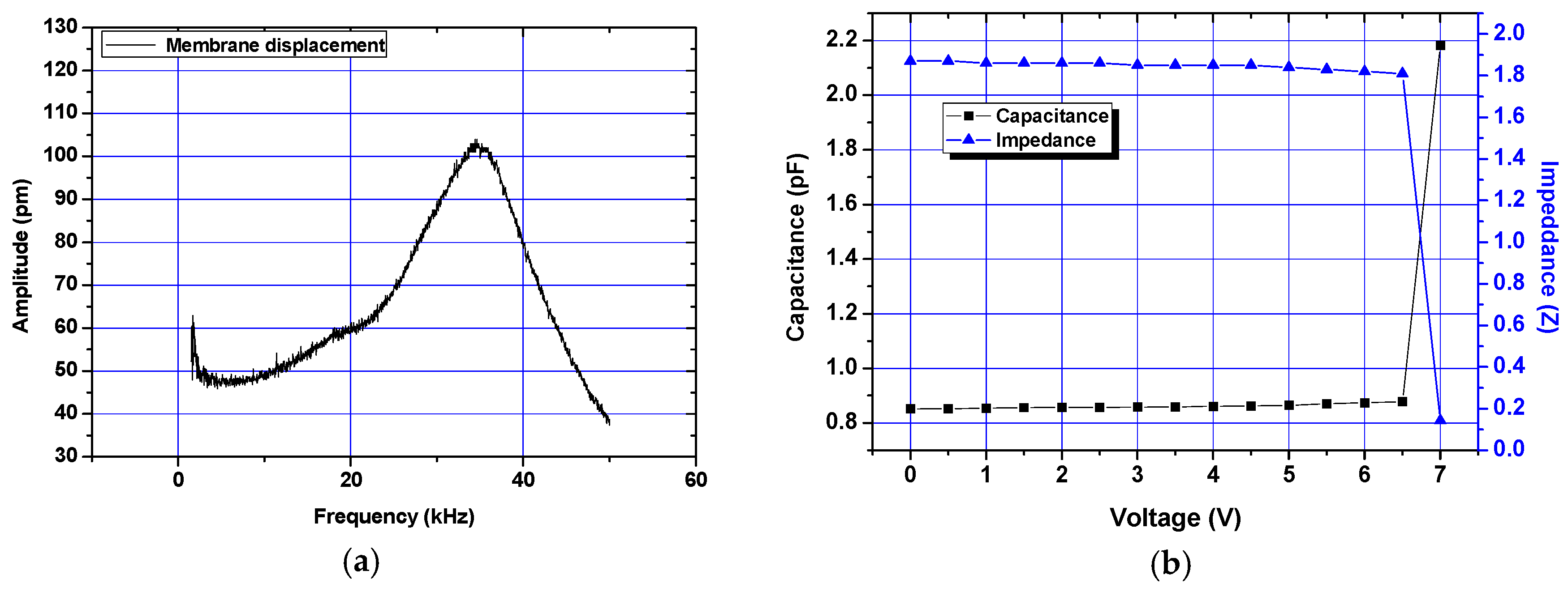
4. Experimental Results

To characterize the effect of the proposed dual anchor, the frequency response and CV curve of the fabricated dual anchored MEMS microphone are measured. The frequency response is measured by using Micro System Analyzer (MSA-400, Polytec GmbH). The sensing membrane was actuated electrostatically with 50 mV AC signal and 4.5 V DC bias. Figure 5a shows the measured frequency responses. To characterize the open-circuit sensitivity, the capacitance and pull-down voltage of the fabricated MEMS microphone are measured using an impedance analyzer (HP 4194A, Agilent). Figure 5b shows the measured C-V data. The pull-down voltage is measured to be 6.55 ± 0.20 V, and the zero-bias capacitances are measured to be 0.86 ± 0.02 pF. The calculated open circuit sensitivity is 14.0 ± 0.8 mv/Pa at a DC bias of 4.5 V. The measured data are summarized in Table 3.
The fabricated dual anchored MEMS microphone shows a below 3.6% deviation within a wafer. By considering other causes of deviation such as the back plate deformation, the residual stress and the air damping, the fabricated MEMS microphone shows a stable operation characteristics.

5. Conclusions

We proposed a MEMS capacitive microphone with a novel dual-anchored membrane. The proposed dual-anchor could minimize the deviation of operating characteristics of the membrane according to the fabrication variation. The membrane is anchored by the back plate insulating silicon nitride structures instead to the sacrificial bottom insulating oxide layer so that its effective size and boundary conditions are not changed according to the process variation. The proposed dual-anchored MEMS microphone is fabricated by the conventional fabrication process without no additional process and mask. From the experimental results, the fabricated MEMS microphone shows a stable operation characteristics so that the proposed dual anchor could contribute the yield.

Acknowledgments

This work was supported by Electronics and Telecommunications Research Institute (ETRI) grant funded by the Korean government. [17ZB1800, Development of Environment & User-Adaptable MEMS Microphone Solution]

Conflicts of Interest

The authors declare no conflict of interest.

References

  1. Lee, J.; Je, C.H.; Yang, W.S.; Kim, Y.G.; Cho, M.H.; Kim, J. Thin MEMS microphone based on package-integrated fabrication process. Electron. Lett. 2012, 48, 866–867. [Google Scholar] [CrossRef]
  2. Leinenbach, C.; Teeffelen, K.; Laermer, F.; Seidel, H. A new capacitive type MEMS microphone. In Proceedings of the International Conference on Micro Electro Mechanical System (MEMS), Hong Kong, 24–28 January 2010; pp. 659–662. [Google Scholar]
  3. Weigold, J.W.; Brosnihan, T.J.; Bergeron, J.; Zhang, X. A MEMS Condenser Microphone for Consumer Applications. In Proceedings of the International Conference on Micro Electro Mechanical System (MEMS), Istanbul, Turkey, 22–26 January 2006; pp. 86–89. [Google Scholar]
  4. Chan, C.-K.; Lai, W.-C.; Wu, M.; Wang, M.-Y.; Fang, W. Design and implementation of a capacitive-type microphone with rigid diaphragm and flexible spring using the two poly silicon micromachining processes. IEEE Sens. J. 2011, 11, 2365–2371. [Google Scholar] [CrossRef]
  5. Je, C.H.; Lee, J.; Yang, W.S.; Kim, J.; Cho, Y.-H. A surface-micromachined capacitive microphone with improved sensitivity. J. Micromech. Microeng. 2013, 23, 1–7. [Google Scholar] [CrossRef]
Figure 1. Schematic view of the proposed MEMS microphone with dual anchored membrane.
Proceedings 01 00342 g001
Figure 2. Cross-sectional view of: (a) Oxide anchored membrane; (b) Dual anchored membrane.
Proceedings 01 00342 g002
Figure 3. Fabrication process of the MEMS microphone with dual anchored membrane.
Proceedings 01 00342 g003
Figure 4. Microscope images: (a) Fabricated MEMS microphone; (b) Enlarged view of the dual anchor.
Proceedings 01 00342 g004
Figure 5. Measurement results of the fabricated MEMS microphone: (a) frequency response; (b) C-V.
Proceedings 01 00342 g005
Table 1. Simulation results of the MEMS microphone according to the membrane anchor deviation.
Membrane Radius (μm)Resonant Frequency (kHz)% errorPull-in Voltage (V)% error
Under etched24532.92−4.146.514.12
Designed25031.61-6.25-
Over etched25530.383.896.01−3.88
Dual-anchored25029.10-6.24−0.14
Table 2. Design parameters of the MEMS microphone with dual anchored membrane.
ParameterMembraneAnchorBack-Plate ThicknessAir Gap
DiameterThicknessDiameter#
μm
values5000.515.0122.32.0
Table 3. Simulation
Table 3. Simulation
ParameterUnitsDesignedMeasured% Deviation
Pull-in voltageV6.246.55 ± 0.22.9
CapacitancepF0.760.86 ± 0.022.4
Resonant frequencykHz29.136.3 ± 1.33.6
Sensitivity (open circuit)mV/Pa 14.0 ± 0.85.7
Publisher’s Note: MDPI stays neutral with regard to jurisdictional claims in published maps and institutional affiliations.

