Abstract
Open-circuit direct piezoelectric coefficients g31 of bi-axially stretched PVDF and chiral PLLA are reported. This measure is decisive for sensor, generator and energy harvesting applications. We use an in-situ method with contactless voltage measurement during a conventional tensile-test, greatly improving measurement precision (error less than 10%).
1. Introduction
Polymers such as poly(vinylide fluoride) (PVDF) have piezoelectric and pyroelectric properties due to their ferroelectric intrinsic chemical formulation and after being subjected to high voltage electrical poling. Other polymers such as Poly-lactic acid (PLA) do not need electrical poling. They develop natural piezoelectricity after mechanical stretching. For the PLA, the stretching creates a non-chiral film poly-l-lactic acid (PLLA) presenting only one shear piezoelectric constant d14 between 10 × 10−12 C.N−1 [1] and 18.9 × 10⁻¹² C.N−1 [2]. This biodegradable polymer presents the advantage of not being pyroelectric, ensuring an absence of drift with the temperature.
To evaluate piezoelectric coefficients, methods such as laser interferometry, low-frequency surface acoustic waves, bimorph bending, or piezo-response force microscopy, are usually used to determine the piezoelectric strength constant d31, determinant for the actuation. In contrast, for sensors, generators and energy harvesting voltage, performances rely on g31 which usually is simply estimated from d31 measurements and almost never measured directly with polymers. This leads to high uncertainty and imprecision (≥30%).
In this work, we consider a new approach [3] to measure directly the g31 coefficient with great reliability (error under 10%). This method, coupled with dielectric constant measurement of the material, allows the determination of the d31 coefficient, which is the one mainly used to express the piezoelectric performance of materials. Measurements have been performed on an experimental PLLA film from TOTAL and a commercial biaxially stretched PVDF film from PIEZOTECH.
2. Experiments
2.1. Sample Preparation
In this study, the PLLA film was obtained from 250 μm thick cast PLA material followed by controlled stretching (5 times) with a tensile test machine at a temperature above the Tg (100 °C). A 100 μm thick monoaxially stretched PLLA film is achieved.
Taking into account the geometric specifications described in [3], samples for our tests are then cut in the 100 μm PLLA film and the 40 μm commercial PVDF film with a length to width ratio upper than 8. The cut samples are then glued with cyanoacrylate glue into 3D-printed clamps and dried for 24 h as shown in Figure 1. The clamps are used to mount the polymer samples into the tensile-test apparatus (MTS) while allowing for in-situ measurements on the samples during stretching. The “active” area between the two clamps has a length of 80 mm and a width of 10 mm.
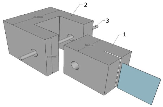
Figure 1.
Schematic drawing of the mounting setup. Part 1 is a 3D-printed clamp in which the polymer is glued. Part 2 is a 3D-printed mounting base attached to the tensile machine. Parts 1 and 2 are held together with pin 3.
Silver conductive grease (CW7100 from CIRCUITWORKS) is subsequently used as electrode material on the active area on both side of the samples. Measurements up to 10% of strain can be performed without electrode damage. Contact with the grease for measurements is insured with thin wires attached to the 3D clamps.
2.2. g31 Determination
In order to extract the piezoelectric coefficient, the tensile test machine is used to strain the film as shown in the Figure 2a. First of all, the force F is registered with a force sensor and the resulting stress σ is determined using sample dimensions: thickness t and width w (1). The strain S is obtained by dividing the direct measurement of the tensile machine’s displacement over the initial sample length. From this measurement, the compliance c31 over a direction is calculated (2).
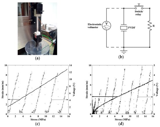
Figure 2.
(a) Picture of a mounted polymer ready to use in the tensile machine. Electrodes are connected to the contactless electrostatic voltmeter and the open-circuit voltage is recorded (Labview software); (b) Schematic of the voltage measurement; (c) Strain-Stress curve and open-circuit output voltage for PLLA sample; (d) Strain-Stress curve and open-circuit output voltage for PVDF sample.
During a tensile cycle, the piezoelectric coefficient g31 is calculated. The method consists in measuring the open-circuit direct piezoelectric voltage by means of a contactless electrostatic voltmeter Trek 370 concurrently to the strain-stress curve of the polymer sample [1]. A switch is used to periodically reset the voltage to zero by discharging the sample into a resistance load, leading to a saw-tooth recorded voltage during the tensile cycle (Figure 2b). The period of the switch is established at 1 s and the pulling speed is set to 2 mm.s−1.
From Equation (3) it can be seen that g31 data is obtained from the slopes of the output voltage V over stress σ. The variability of the g31 coefficient is obtained by repeating the tensile cycle up to 10 times. To do so, the measurement is restricted to elastic zone of each polymer. An example of one tensile cycle measurements is represented in Figure 2c for PLLA and Figure 2d for PVDF.
To verify the achieved properties of the PLLA film, different specimens have been cut with an angle from the polling axis. According to [1], PLLA only has one shear constant (g14) that can be measured as a “g31” (strain perpendicular to electric field) by cutting the sample at 45° from the stretching axis. According to [1], the measured “g31” is at this point equal to 1/2 g14.
The average measured “g31” in Figure 3a experimentally validates the g14 PLLA shear mode hypothesis, with a maximum at 45° and a decreasing coefficient to the polling axis and perpendicular to this axis. The resulting g31 for both PVDF (66 ± 5 mV.m.N−1) and PLLA (64 ± 7 mV.m.N−1) over the stress are comparable as shown in the Figure 3b. Used as sensors, those two materials will generate the same amount of voltage. The measurements show a g14 coefficient for PLLA of 128 ± 14 mV.m.N−1.
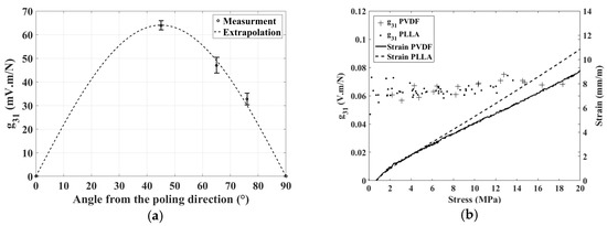
Figure 3.
(a) Influence of the angular direction on the piezoelectric coefficient g31 of the PLLA from the stretching direction; (b) Dependences of the direct piezoelectric voltage coefficient g31 and strain-stress curve for PVDF and PLLA (at 45° from the stretching axis).
2.3. Impedance Measurements
Impedance measurements are performed between 1 kHz and 100 kHz with a HIOKI impedance-meter as shown in Figure 4a,b. The equivalent electrical circuit consists on an access resistor in series with a capacitor and a resistor in parallel. The capacitor is representative of the relative dielectric constant ε33 of the polymer and its parallel resistor is linked to its dielectric losses. The PVDF presents a ε33 of 6.82 ± 0.01 and the PLLA of 2.82 ± 0.02.
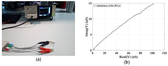
Figure 4.
(a) Pictures of the impedance measurement with the HIOKI impedance-meter; (b) Nyquist representation of the admittance of the PLLA between 1 kHz and 100 kHz.
2.4. d31 Determination
From the previous measurements (ε33. and g31), the d31 coefficient of each polymer can be extracted by means of Equation (4). More widespread than g31, it represents the electro-mechanical transduction. From the calculated coefficients (Table 1), the PLLA working in d14 mode is comparable to the PVDF in d31 mode for the actuation. The tested PLLA film presents piezoelectric d14 values below those of literature (10 × 10−12 C.N−1 [1] and 18.9 × 10⁻¹² C.N−1 [2]) as it is still under development.

Table 1.
Obtained coefficient of PVDF and PLLA.
3. Discussion and Summary
Original experimental results of in situ direct measurements of g31 voltage coefficient and ε33 relative dielectric coefficient of chiral PLLA and bi-axially stretched PVDF were reported. We showed great improved measurement precision (error less than 10%) on g31. This is decisive for sensor, generator and energy harvesting applications. These measurements allow the calculation of the piezoelectric coefficient d31 which determines actuator performance. We conclude that PLLA biopolymers are good candidates to generate electricity, comparable to PVDF. For actuator purposes, PLLA is behind PVDF because of a low ε33 but its thermal drift is less important.
References
- Ochiai, T.; Fukada, E. Electromechanical properties of the Poly-l-Lactic Acid. Jpn. J. Appl. Phys. 1998, 37, 3374–3376. [Google Scholar] [CrossRef]
- Yoshida, M.; Onigi, Y.; Onishi, K.; Inagaki, T.; Tajitsu, Y. High piezoelectric performance of poly(lactic acid) film manufactured by solid-state extrusion. Jpn. J. Appl. Phys. 2014, 53, 09PC02. [Google Scholar] [CrossRef]
- Gusarov, B.; Gusarova, E.; Viala, B.; Gimeno, L.; Cugat, O. PVDF piezoelectric voltage coefficient in situ measurements as a function of applied stress. J. Appl. Polym. Sci. 2016, 133, 1–6. [Google Scholar] [CrossRef]
Publisher’s Note: MDPI stays neutral with regard to jurisdictional claims in published maps and institutional affiliations. |
© 2017 by the authors. Licensee MDPI, Basel, Switzerland. This article is an open access article distributed under the terms and conditions of the Creative Commons Attribution (CC BY) license (https://creativecommons.org/licenses/by/4.0/).