1. Introduction
This work introduces a low-cost fabrication method for Electrowetting-on-Dielectric (EWOD) structures for microsystem and Lab-on-a-Chip applications. The electrowetting effect has been described first by Vallet and Berge [
1]. Integrating a large number of sensors on a single device is a common task for Lab-on-a-Chip related research [
2].
In recent works the focus often has been on sensing certain fluid properties like viscosity and density with resonant viscosity sensors or other small devices, which are feasible for arrangement inside an integrated Lab-on-a-Chip system [
3]. We will see that the electrowetting effect can be utilized to build a small device allowing to differentiate between the viscosities of various fluid droplets.
Building an EWOD stack usually requires expensive equipment, like vapour deposition for the electrodes and parylene C coating devices to obtain hydrophobic and dielectric coatings. This work demonstrates a low-cost approach for rapid prototyping EWOD stacks, which will then be used as a basic structure for the presented viscosity sensing device.
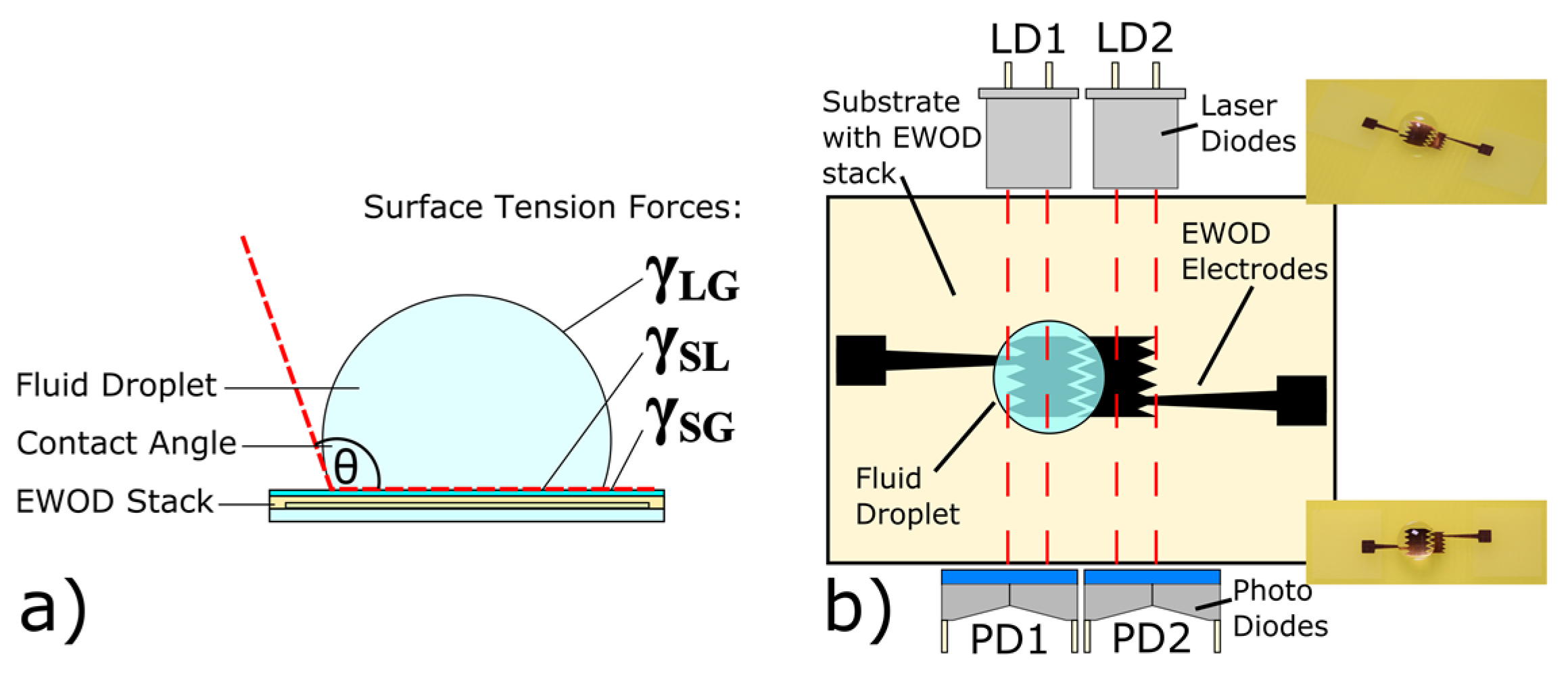
Figure 1a shows how the contact angle (CA)
θ of a droplet on a given substrate depends on the equilibrium of three surface tensions, i.e., at the triple contact line (TCL) between the liquid, gaseous and solid phase (
γLG,
γSG,
γSL) according to Young´s equation:
The figure shows a droplet resting on top of an EWOD stack, consisting of a suitable substrate, electrodes, a dielectric insulation layer, and a hydrophobic layer. This system can now experience a disturbance in the mentioned equilibrium by applying a voltage
V to the electrode layer beyond the droplet. The contact angle then changes according to the well-known Lippmann Young formula
where
θV is the actuated CA,
t the combined thickness of the dielectric and hydrophobic layer,
V the applied EWOD voltage, and
ε0 εr is the permittivity of the dielectric layer.
A droplet slightly overlapping two EWOD electrodes will experience an imbalance in inner pressure, if one electrode is set to GND and the EWOD voltage V
APP is applied to the second electrode. In this case, the CA above the second electrode will adapt to the newly created equilibrium. This gives rise to an inner pressure difference Δ
p described by the Laplace formula
The droplet will subsequently move in direction of the smaller CA.
R1 and
R2 indicate the curve radii on both, the actuated and the non-actuated side of the droplet.
Figure 1b introduces a scheme of the absorption EWOD (aEWOD) switch. It consists of an EWOD stack, two electrodes and two laser- and photodiodes (LD1/LD2 and PD1/PD2) where each laserdiode is exactly facing the associated detection photodiode. In the displayed state, PD1 shows a lower signal than PD2 due to the absorption of a water droplet. After moving the droplet to the right hand side electrode by EWOD forces, PD2 shows a lower signal than PD1. The time difference Δ
t between the two signal edges, measured with an oscilloscope, can be used to determine the time it takes the droplet to move from the left electrode 1 to the right electrode 2. This time difference Δ
t is strongly viscosity dependent as we will see in
Section 3 (Modeling).
2. Fabrication
We focused on rapid processing and prototyping of the used EWOD stack. As a substrate we used the commercially available printed circuit substrate material FR4 with a 15 µm Cu layer. The Cu electrodes have been processed by wet etching. The negative photoresist SU-8 2005 from Micro ChemicalsTM has been used as dielectric insulation because of its easy processing by spin coating and high dielectrical breakdown strength of about 440 V/m. Propylene glycol methyl ether acetate (PGMEA) has been used for the SU-8 development and Polytetrafluoroethylene (PTFE TeflonTM AF601 from DuPontTM, θ0 = 118°) has been used as hydrophobic layer. InGaAs IR photodetectors (LAPD-1-09-17-LCC) with a response maximum at λ = 1550 nm and IR single mode 1540 nm laser diodes (S1550-5MG) from Roithner Laser TechnikTM have been used for the detection part of the aEWOD device.
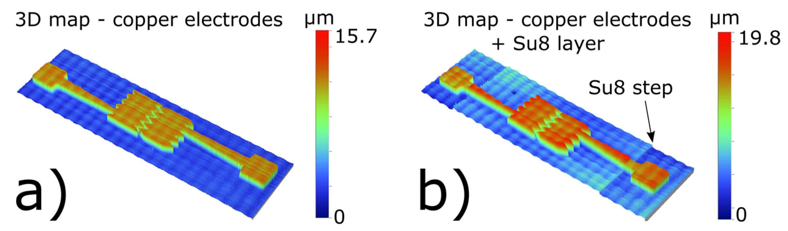
Figure 2 shows a 3D map scan measured with a Bruker DekTak XT profilometer. Scan (a) shows the FR4 board with the plain, wet-etched Cu electrodes. Scan (b) shows the Cu electrodes, covered with a 4 µm layer of SU-8 and uncovered electrode contacts. This change of 4 µm is visible in the height map of the scans. Because of the negligible thickness of the hydrophobic layer (
d ~ 200 nm), a 3D map of the PTFE-coated stack is not necessary for a proper EWOD stack characterization.
Based on the profilometer measurements, the simulation parameters (combined layer thickness t, electrode geometry and initial contact angle θ0) for the EWOD stack are specified and can hereinafter be used for modeling of the EWOD effect.
3. Modeling
Modeling in terms of Computational Fluid Dynamics (CFD) has been implemented with the commercial software COMSOL
TM Multiphysics 5.2. For the absorption simulations, the geometric optics module has been used. For the fluid dynamics, the laminar flow two phase flow module combined with the Phasefield interface tracking algorithm has been used. The used PhaseField interface tracking method coupled with the Navier-Stokes equations is one of the most promising and rather new approaches for handling moving contact lines and fluid-fluid interfaces [
4].
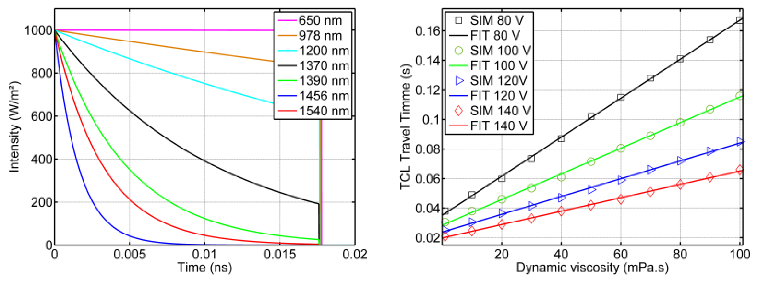
Figure 3 left shows the intensity of the attenuated laser light with various wavelengths
λ versus time if the light becomes attenuated by a water droplet with slightly more than 3.7 mm diameter at the base (~electrode length). The intensity of the light decreases according to the well-known Beer-Lambert law as it propagates through the absorbing medium. Light emitted by a standard 650 nm laser hardly experiences any attenuation in intensity because the extinction coefficient is near to zero in this wavelength range, leading to no measurable intensity difference between LD1 and LD2. We use a 1540 nm infrared laser to get a clear attenuated and measurable signal.
Figure 3 right shows CFD simulation results of the droplet’s dynamic viscosity
η vs. the average travel time
tTCL of the droplet’s moving triple contact line over a distance of 3.7 mm, a dimension given by the electrode length. The bigger the viscosity, the slower the droplet moves from electrode 1 to electrode 2. The traveling speed of the triple contact line increases for higher EWOD voltages. The course of the TCL travel time
tTCL shows a clear linear dependence on the viscosity.


