Article

FPGA Implementation of Secure Image Transmission System Using 4D and 5D Fractional-Order Memristive Chaotic Oscillators

by
Jose-Cruz Nuñez-Perez
1,*,
Opeyemi-Micheal Afolabi
1,
Vincent-Ademola Adeyemi
1,
Yuma Sandoval-Ibarra
2 and
Esteban Tlelo-Cuautle
3
1
Instituto Politécnico Nacional, IPN-CITEDI, Av. Instituto Politécnico Nacional No. 1310, Tijuana 22435, Mexico
2
Tecnológico Nacional de México, Instituto Tecnológico de Tijuana, TecNM-ITT, Calzada Tecnológico No. 12950, Tijuana 22414, Mexico
3
Instituto Nacional de Astrofísica, Óptica y Electrónica, INAOE, Luis Enrique Erro #1, San Andrés Cholula 72840, Mexico
*
Author to whom correspondence should be addressed.
Fractal Fract. 2025, 9(8), 506; https://doi.org/10.3390/fractalfract9080506
Submission received: 28 June 2025 / Revised: 24 July 2025 / Accepted: 29 July 2025 / Published: 31 July 2025

Abstract

With the rapid proliferation of real-time digital communication, particularly in multimedia applications, securing transmitted image data has become a vital concern. While chaotic systems have shown strong potential for cryptographic use, most existing approaches rely on low-dimensional, integer-order architectures, limiting their complexity and resistance to attacks. Advances in fractional calculus and memristive technologies offer new avenues for enhancing security through more complex and tunable dynamics. However, the practical deployment of high-dimensional fractional-order memristive chaotic systems in hardware remains underexplored. This study addresses this gap by presenting a secure image transmission system implemented on a field-programmable gate array (FPGA) using a universal high-dimensional memristive chaotic topology with arbitrary-order dynamics. The design leverages four- and five-dimensional hyperchaotic oscillators, analyzed through bifurcation diagrams and Lyapunov exponents. To enable efficient hardware realization, the chaotic dynamics are approximated using the explicit fractional-order Runge–Kutta (EFORK) method with the Caputo fractional derivative, implemented in VHDL. Deployed on the Xilinx Artix-7 AC701 platform, synchronized master–slave chaotic generators drive a multi-stage stream cipher. This encryption process supports both RGB and grayscale images. Evaluation shows strong cryptographic properties: correlation of 6.1081 × 10 5 , entropy of 7.9991, NPCR of 99.9776%, UACI of 33.4154%, and a key space of 2 1344 , confirming high security and robustness.

1. Introduction

As conventional image encryption techniques increasingly struggle to withstand sophisticated brute-force and cryptanalytic attacks, alternative methods grounded in nonlinear dynamics have emerged as promising candidates for secure image transmission. The rapid expansion of digital communication technologies not only has amplified the volume of transmitted image data, but also has heightened the demand for robust and lightweight encryption mechanisms suitable for real-time applications [1,2]. Among these alternatives, chaotic systems have attracted considerable attention due to their intrinsic properties such as sensitivity to initial conditions, pseudo-random behavior, and ergodicity, which are desirable for encryption [3,4,5]. In particular, high-dimensional chaotic systems have demonstrated improved key-space size and complexity, enabling overall enhanced security of image encryption schemes [6].
Despite this progress, the integration of memristive elements within chaotic systems remains a relatively underexplored domain, especially when considering fractional-order dynamics. Additionally, the real-time hardware realization of such systems poses significant challenges because of the computational complexity of fractional calculus and the high dimensionality of chaotic models. Field-programmable gate arrays (FPGAs), however, offer a compelling platform for implementing these systems due to their inherent parallelism, configurability, and ability to meet real-time processing requirements in embedded environments [7]. For instance, in [8] FPGAs have been successfully used in the design of a chaotic oscillator exhibiting multiple coexisting attractors. Moreover, numerous studies have demonstrated the FPGA-based realization of traditional chaotic systems, including fractional-order variants of the Chen, Lü, Rössler, Lorenz, and Chua circuits [9,10].
A significant paradigm shift in the development of chaotic systems has emerged through the integration of memristive elements, which are nonlinear, passive circuit components characterized by non-volatility, time non-locality, and memory-dependent behavior. These properties enable memristive elements to emulate complex dynamical phenomena, particularly in systems where past states influence present responses, making them ideal for modeling memory-rich dynamical systems [11]. When embedded within chaotic oscillators, they substantially increase the system’s dynamic richness, enhance unpredictability, and diversify the range of attainable trajectories [12]. This heightened complexity is particularly valuable in the context of unconventional computing, where traditional approaches fall short in handling adaptive, nonlinear, and history-sensitive computations. The unique capabilities of memristive elements have catalyzed their application across a broad spectrum of fields, including information security [13], numerical equation solving [14], image processing [15], and neuromorphic computing [16]. Noteworthy recent contributions include the work presented in [17], which proposes a memristor-driven polynomial hyperchaotic system for robust multi-channel image encryption, realized through a cross-coupled memristor configuration. Another significant recent effort by [18] presents a digital hardware synthesis and dynamical behavior characterization of a novel four-dimensional fractional-order Hopfield neural model with memristor-based nonlinearity. Addressing the computational demands of feature extraction, [19] proposes a parallel architecture based on memristor crossbars to accelerate and achieve rotational robustness of Oriented FAST and Rotated BRIEF algorithms. A neurodynamics-based approach for solving nonlinear matrix equations, including a non-iterative Riccati equation solver, is proposed in [20], with demonstrated accuracy sufficient for practical applications.
Extending these systems to the fractional-order domain introduces additional degrees of freedom in system dynamics, enabling richer chaotic behavior [21]. Although the concept of memristive systems has existed for over half a century, their experimental and practical deployment are still in their early stages. Nonetheless, their unique properties positions them as a promising foundation for emerging unconventional computing paradigms, opening new frontiers for research and innovation in complex dynamical systems [22,23,24,25,26,27,28]. Generally, fractional-order models (FOMs) often exhibit behaviors that are closer to reality than integer-order models [29]. Fractional calculus (FC), as a mathematical generalization of classical calculus, offers a more granular representation of a wide array of systems in diverse scientific and engineering domains where better predictive capabilities and more effective control strategies are required [30]. Therefore, studying the behaviors of systems using FOMs is more practical and reflective of real-world phenomena. Although the notion of FC is not new to the scientific community, its practical application to many physical problems has only gained significant momentum in recent years. FC is characterized by a variety of mathematical definitions and notational conventions, with commonly used formulations including the Caputo, Riemann–Liouville, and Grünwald–Letnikov derivatives [31,32,33,34,35,36]. Despite differences in their formalism and application contexts, these definitions share a unified conceptual foundation.
Among these, the Caputo fractional derivative (CFD) is one of the most widely used in modeling physical and engineering systems due to its compatibility with traditional initial conditions [37]. While the Grünwald–Letnikov (GL) numerical method provides an effective means of approximating Caputo-based systems, it requires recursive summation over all previous states to compute the current one. This introduces a significant memory overhead which can make real-time hardware implementations, such as those on FPGAs, computationally intensive and potentially slow [38,39]. To address this challenge, more computationally efficient numerical techniques have been explored. One such approach is the explicit fractional-order Runge–Kutta (EFORK) method [40], which reduces memory requirements while maintaining acceptable numerical accuracy. Due to its low-resource characteristics and compatibility with real-time processing, the EFORK method is particularly well-suited for implementing fractional-order systems in hardware environments.
In the domain of image security, FOMs of chaotic systems have been explored in several frameworks and are well-documented in the literature. For example, in [41], an image encryption system that uses multi-stage hash-based indexing mechanism to enhance key sensitivity and diffusion characteristics is proposed. The system uses a fractional-order chaotic system derived from a Hopfield neural network comprising four neurons as the pseudo-random generator. In [42], the authors proposed a secure image transmission scheme based on a memristive neural network model governed by variable-order fractional dynamics that uses a synchronization-based control strategy to ensure coordinated chaotic behavior between transmitter and receiver. In [43], an image encryption system was developed using a hyperbolic tangent-based memristive chaotic oscillator with six dimensions and fractional-order dynamics to enhance complexity and security. In [44], a medical image encryption scheme is introduced that uses a dynamic neural system operating in the tetradimensional fractional domain. Additionally, in [45], an image encryption algorithm was introduced based on the hybridization of a fractional-order memristive chaotic system and a generalized Arnold map, implemented through the GL approximation technique.
In this paper, we present the FPGA-based implementation of a secure image transmission system using fractional-order four-dimensional (4D) and five-dimensional (5D) memristive chaotic systems. The proposed framework achieves secure communication by synchronizing identical chaotic oscillators-modeled in 4D and 5D-through a master–slave configuration using a combination of Hamiltonian formulation and observer-based control. This synchronization mechanism ensures the coordinated evolution of the transmitter and receiver states, thereby enabling accurate recovery of the encrypted image data at the receiver end. The major contributions of this research are stated as follows:
(i)
The hardware implementation of fractional-order chaotic oscillators based on 4D and 5D memristive systems, realized on FPGA using EFORK method for iterative approximation of system trajectories in VHSIC Hardware Description Language (VHDL).
(ii)
The synchronization of two identical fractional-order chaotic oscillators based on memristive systems in a master–slave topology using Hamiltonian form and observer approach to facilitate secure information transmission, with digital implementations on an Artix-7 AC701 (AMD, Santa Clara, CA, USA) evaluation board.
(iii)
The modular design of transmitter–receiver architecture integrating observer-based synchronization and a multi-stage image encryption pipeline fully implemented in hardware.
The remainder of this paper is structured as follows: Section 2 presents the necessary preliminaries and theoretical background, including an overview of fractional-order systems, the EFORK numerical integration method, and synchronization techniques. Section 3 details the design and mathematical modeling of the proposed 4D and 5D fractional-order memristive chaotic oscillators. Section 4 describes the image encryption and decryption processes, highlighting the multi-stage transformation pipeline driven by synchronized chaotic dynamics. Section 5 focuses on the FPGA-based implementation of the secure image transmission system, covering the hardware realization of the EFORK method, the synchronization mechanism, and the parallel pipelined architecture for image encryption and decryption. Section 6 provides a comprehensive security and performance analysis, including correlation, entropy, differential attack resistance, and hardware resource utilization. Section 7 presents a comparative analysis of the proposed system against existing approaches and outlines potential directions for future research. Finally, Section 8 concludes the paper and summarizes the key findings.

2. Preliminaries

2.1. Fractional Calculus

FC is an extension of classical calculus, which traditionally operates on integer-order differentiation and integration such as f ( t ) and a b f ( x ) d x to the domain of arbitrary order α [46]. Unlike integer-order operators, fractional operators inherently incorporate memory effects, meaning the output depends not only on the current input but also on the entire history of the function. This is commonly denoted as D α f ( x ) where α R . One of the most widely used formulations in engineering applications is the CFD, which is defined as shown in Equation (1),
D t α a c = 1 Γ ( m a ) a t f ( m ) ( τ ) ( t τ ) α + 1 m d τ ( m 1 ) < α < m d m d t m f ( t ) α = m ,
where α > 0 and f ( t ) L 1 [ a , b ] , with a 0 , Γ ( · ) is the gamma function described as Equation (2) for any real numbers z > 0 [47],
Γ ( z ) = 0 t z 1 e t d t .
The Riemann–Liouville’s definition captures the idea of fractional-order derivatives and integral operators in a unified framework as expressed in the mathematical formulation in Equation (3),
D m α f ( t ) = 1 Γ ( n α ) d n d t n m t ( t τ ) n α 1 f ( τ ) d τ ( n 1 < α < n ) .
The GL definition follows a discretized approach, and it is often used in several numerical and digital implementations. It is mathematically described as Equation (4),
D α f ( t ) = lim h 0 1 h α k = 0 t h ( 1 ) k α k f ( t k h ) .

2.2. Explicit Fractional-Order Runge Kutta (EFORK) Numerical Method

The s-order EFORK method [40] constructed by the generalized Taylors series of Caputo’s form for an initial value problem presented in Equation (5) can be described as Equations (6) and (7),
D t α t 0 C y ( t ) = f ( t , y ( t ) ) , t [ t 0 , T ] , 0 < α 1 y ( t 0 ) = y 0 ,
K 1 = h α f ( t , y ) , K 2 = h α f ( t + c 2 h , y + a 2 , 1 K 1 ) , K 3 = h α f ( t + c 3 h , y + a 3 , 1 K 1 + a 3 , 2 K 2 ) , K s = h α f ( t + c s h , y + a s , 1 K 1 + a s , 2 K 2 + + a s , s 1 K s 1 ) ,
y n + 1 = y n + t = 1 s w t K t ,
where y ( t ) C [ t 0 , T ] , f ( t , y ( t ) ) C [ t 0 , T ] × R , and the optimal unknown coefficients a i j for i = 2 , , s , j = 1 , i 1 as well as the optimal unknowns weights c i for i = 2 , , s and w i for i = 1 , s for EFORK of order 2 α can be determined in accordance to Equation (8),
c 2 = 4 Γ ( α + 1 ) Γ ( 3 α + 1 ) 1 α , a 21 = 4 Γ ( 3 α + 1 ) , w 1 = 1 Γ ( α + 1 ) Γ ( 3 α + 1 ) 4 Γ ( 2 α + 1 ) , w 2 = Γ ( 3 α + 1 ) 4 Γ ( 2 α + 1 ) .

2.3. Hamiltonian Form and Observer Synchronization of Chaotic Systems

Chaotic systems are nonlinear deterministic dynamical systems that exhibit complex and seemingly unpredictable behavior due to their sensitivity to initial conditions, ergodicity, aperiodicity, and boundedness. Although such systems inherently resist synchronization, numerous studies have been devoted to developing strategies for achieving synchronization between identical or non-identical chaotic systems [48,49,50,51,52]. One well-established approach combines the Hamiltonian canonical form with observer-based control, which enables the construction of stable synchronization schemes by transforming the chaotic system into a structure amenable to control design. This strategy is particularly effective in master–slave configurations, where the transmitter (master) drives the receiver (slave) to converge to identical trajectories. Let us consider two fractional-order dynamical systems that can be represented in the Hamiltonian form in Equation (9),
D t α t 0 C y = f ( y ) ,
where y R n is the state variable of the nonlinear mapping f : R n R n . Equation (9) can be expressed in the form of Equation (10),
D t α t 0 C y = A H ( y ) y + Φ ( y ) ,
where H ( y ) = 1 / 2 y T M y is the energy function that is positive definite in R n , H / y = M y is its column gradient vector with respect to y, M is a symmetric positive definite constant matrix, and A is the sum of the square matrices J ( y ) = ( A + A T ) / 2 , and S ( y ) = ( A A T ) ) / 2 which, satisfies J ( y ) + J T ( y ) = 0 and S ( y ) = S T ( y ) , respectively, ∀ y R n . By substituting the matrices J ( y ) and S ( y ) into Equation (10) we can derive Equation (11),
D t α t 0 C y = A + A T 2 H y + A A T 2 H y + Φ ( y ) ,
which can be re-written in the Hamiltonian canonical form (12),
D t α t 0 C y = J ( y ) H y + S ( y ) H y + Φ ( y ) .
By considering the master system as a special class of the generalized Hamiltonian form with destabilizing vector field and output vector x ( t ) , in the case of an observer approach, Equation (13) can be constructed as,
D t α t 0 C y = J ( x ) H x + S ( x ) H x + Φ ( x ) y R n x = η H y , x R n ,
where η is a constant matrix and S ( x ) can be written as S ( x ) = I ( x ) + W ( x ) , where I ( x ) is a constant skewed symmetric matrix and W ( x ) is a constant symmetric matrix that is not necessarily of definite sign [53].
In the same vein, a slave system that approximates the trajectory of the master system through observing its state can be constructed by choosing the estimate state vector of y as ζ and the estimated output as κ . The observing system is then given in Equation (14),
D t α t 0 C ζ = J ( x ) H ζ + S ( x ) H ζ + Φ ( x ) + K e x , ζ R n κ = η H ζ , κ R n ,
where K is the observer gain of the system and e x = x κ is the prediction discrepancy while the estimation deviation in the states of the systems can be defined as e = y ζ . It is important to note that the states of the master and slave systems are considered fully synchronized if and only if the absolute value of their phase difference converges to zero, as mathematically expressed in Equation (15). This condition is satisfied when Theorems 1 and 2 hold, ensuring the theoretical basis for asymptotic synchronization [54].
lim t | y m ( t ) ζ m ( t ) | = 0 .
Theorem 1.
The state y of the nonlinear system in (13) can be globally, exponentially, and asymptotically estimated by the state ζ of the nonlinear observer in (14) if the pair of matrices ( η , S ) is observable [53].
Theorem 2.
The state y of the nonlinear system in Equation (13) can be globally, exponentially, and asymptotically estimated by the state ζ of the nonlinear observer in (14) if and only if ∃ a constant matrix K such that the symmetric matrix as described in Equation (16),
[ S K Y ] + [ S K Y ] T = [ W K Y ] + [ W K Y ] T = 2 [ W 1 / 2 ( K Y + Y T K T ) ]
is negative definite [53].

3. Fractional-Order Universal Memristive Systems

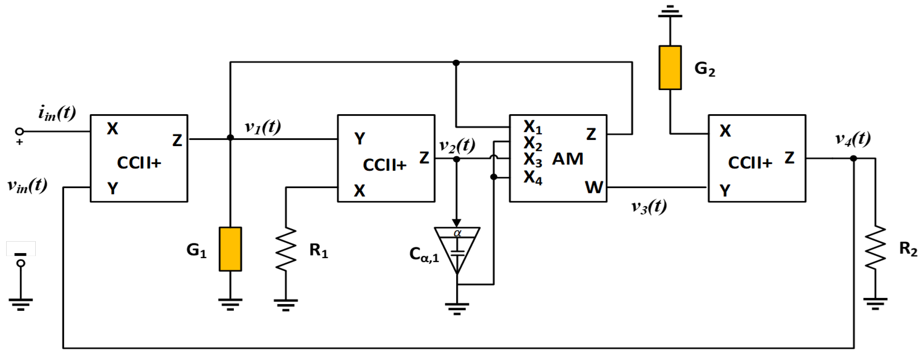
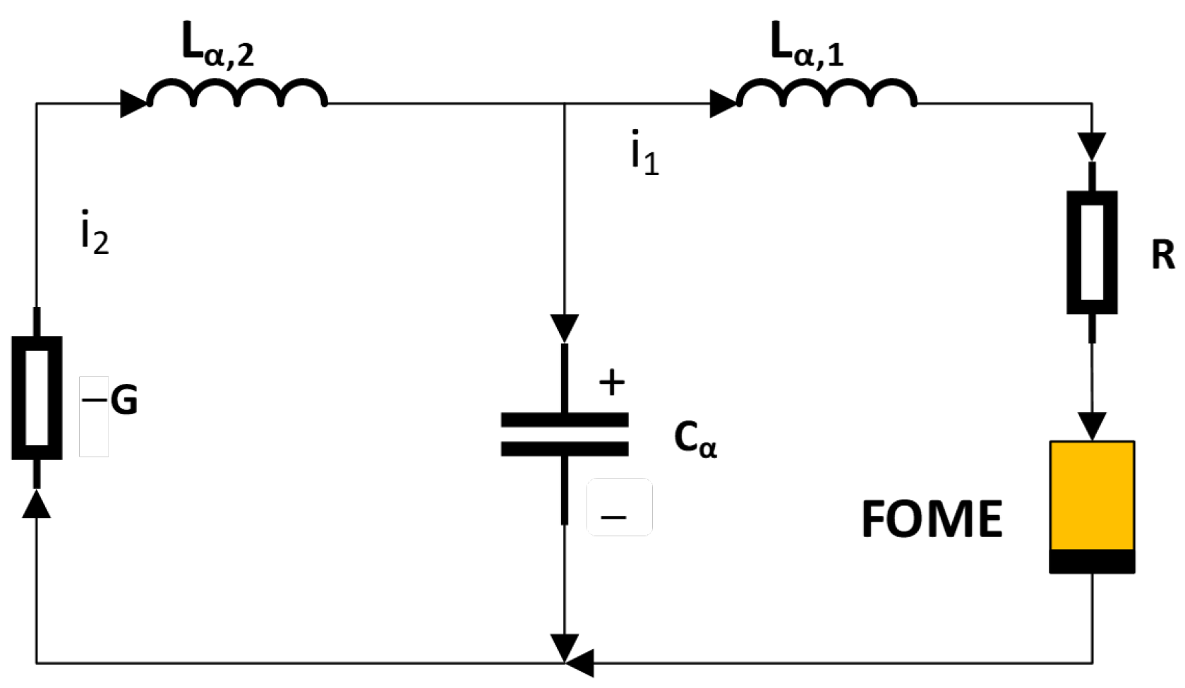
3.1. Reconfigurable Memristive Emulator Circuit of Arbitrary Order

The dimensionality of the universal memristive emulator proposed in [55] can be extended to the fractional-order domain by replacing the conventional capacitor with a fractional-order capacitor (FOC), denoted as C α , as shown in Figure 1. The impedance of this element follows a power-law behavior governed by the order α , thereby introducing enhanced memory and frequency-dependent dynamics into the system. The resulting emulator architecture comprises three second-generation current conveyors (CCII+), whose port characteristics are defined in Equation (17), an analog multiplier (AM) characterized by the transfer function in Equation (18), and a set of passive components.
v x = v y , i y = 0 , i z = i x
v w = ( v x 1 v x 2 ) ( v x 3 v x 4 ) 10 + v z
When components G 1 and G 2 in Figure 1 are configured as resistors R 0 and R 3 , respectively, the voltage–current relationship of the fractional-order memristive element can be derived as shown in Equation (19). In this configuration, R 2 and R 3 are standard resistors that define the memristive behavior by interacting with the fractional-order dynamics.
v i n ( t ) = R 0 R 2 R 3 i i n ( t ) + R 0 2 R 2 10 R 1 R 3 C α , 1 i i n ( t ) a C D t α i i n ( t )
Similarly, under an alternative configuration where G 1 is replaced by a fractional-order capacitor C α , 0 and G 2 remains a resistor R 3 , the voltage–current relationship becomes Equation (20),
v i n ( t ) = R 2 R 3 C α , 0 D t α a c C i i n ( t ) + R 2 10 R 1 R 3 C α , 1 C α , 0 D t α a c C i i n ( t ) ( a C D t α ) 2 i i n ( t )
A third configuration, shown in Equation (21), is obtained by configuring G 1 as a resistor R 0 and substituting G 2 with a fractional-order capacitor C α , 0 of order α :
ϕ ( t ) = R 0 R 2 C α , 0 i i n ( t ) + R 0 2 R 2 C α , 0 10 R 1 C α , 1 i i n ( t ) a C D t α i i n ( t ) .

3.2. A New Fractional-Order Model of Universal Memristive Chaotic System

The oscillator circuit architecture originally introduced in [55] can be extended to support fractional-order dynamics by systematically replacing its conventional components with their fractional-order analogs. Specifically, the generalized design integrates a fractional-order capacitor C α , two fractional-order inductors L α , 1 and L α , 2 , and a fractional-order memristive element (FOME). These elements, characterized by memory-dependent and non-local behavior, are embedded within the enhanced circuit configuration illustrated in Figure 2, which also includes standard linear components such as a resistor R and a negative conductance G .
The dynamic response of the chaotic oscillator circuit can then be mathematically characterized as a fractional-order system by applying Kirchhoff’s laws together with the Caputo definition of the fractional derivative, as formulated in Equation (22).
L α , 1 D t α t 0 C i 1 = v c R i 1 v m ( q ) , C α D t α t 0 C v c = i 2 i 1 , L α , 2 D t α t 0 C i 2 = i 2 G v c , D t α t 0 C q = i 1 ,
Here, v c , q , i 1 , and i 2 are state variables and v m ( q ) is the voltage across the terminals of the fractional-order charge-controlled memristive element.

3.3. 4D Memristive Fractional-Order Chaotic System

For notational simplicity, we define q ( t ; α ) = D t α a c C i in ( t ) and σ ( t ; α ) = D t α a c C 2 i in ( t ) . Using these definitions, a 4D fractional-order system can be formulated from the framework of Equation (22), when the FOME in Figure 2 adopts the configuration described by Equation (19). The governing dynamics of the resulting system are expressed in Equation (23).
D t α t 0 C i 1 = 1 L α , 1 v c R i 1 R 0 R 2 R 3 + R 0 2 R 2 10 R 1 R 3 C α , 1 q i 1 , D t α t 0 C v c = 1 C α i 2 i 1 , D t α t 0 C i 2 = 1 L α , 2 i 2 G v c , D t α t 0 C q = i 1 ,
A time-domain scaling transformation is applied to the system described in Equation (23) in order to obtain a simplified representation given by Equation (24). This is achieved by introducing the scaled time variable t = L α , 2 d τ and defining the state variables as x = i 1 , y = v c , z = i 2 , and w = q / L α , 2 . Additionally, the system parameters are redefined for convenience as follows: a = L α , 2 L α , 1 , b = L α , 2 C α , c = R , k = 1 G , m = R 0 R 2 R 3 , and n = R 0 2 R 2 R 1 R 3 C α , 1 .
D t α t 0 C x = a y c x m + n w x , D t α t 0 C y = b z x , D t α t 0 C z = k z y , D t α t 0 C w = x .
Figure 3a presents the bifurcation diagram of the 4D nonlinear system defined in Equation (24), illustrating the transition from periodic to chaotic behavior as the fractional-order parameter α is varied. The analysis is conducted using fixed system parameters a = 2 , b = 1 , c = 0.2 , k = 0.92 , m = 0.002 , and n = 0.04 , with initial conditions set to ( x 0 , y 0 , z 0 , w 0 ) = ( 0.01 , 0.01 , 0.01 , 0.01 ) .
To further characterize the chaotic dynamics, the Lyapunov exponent (LE) spectrum of the system is computed and shown in Figure 3b. The LE spectrum provides a quantitative assessment of the sensitivity of the system to initial conditions, serving as a fundamental tool in the analysis of chaotic systems [56]. For a fractional-order parameter α = 0.99999 , the computed spectrum yields the set of exponents ( 0.3542 , 0.1009 , 0.1090 , 2.6314 ) , indicating the presence of hyperchaotic behavior due to the existence of at least two positive Lyapunov exponents.
Figure 4a–f collectively illustrates the rich dynamical characteristics of the system, including phase portraits and time-series trajectories, generated over a simulation period of t = 1000 s with a numerical step size of h = 0.01 . The simulations are carried out using the EFORK method described in Section 2.1, which provides accurate approximation for fractional-order systems.

3.4. 5D Memristive Fractional-Order Chaotic System

Following a similar derivation procedure, the system can be extended by configuring the FOME in Figure 2 according to the mathematical model described in Equation (20). This configuration yields the dynamical system expressed in Equation (25),
D t α t 0 C i 1 = 1 L α , 1 v c R i 1 R 2 R 3 C α , 0 + R 2 10 R 1 R 3 C α , 1 C α , 0 σ q , D t α t 0 C v c = 1 C α i 2 i 1 , D t α t 0 C i 2 = 1 L α , 2 i 2 G v c , D t α t 0 C q = i 1 .
Notably, the resulting formulation comprises four differential equations in five state variables, indicating that the system is underdetermined in its current form. To render the system solvable and ensure a well-posed dynamical framework, it is necessary to augment the system with an additional differential equation corresponding to the evolution of the auxiliary state variable σ . Accordingly, the system originally presented in Equation (22) is extended and restructured to yield the 5D fractional-order system presented in Equation (26),
D t α t 0 C i 1 = 1 L α , 1 v c R i 1 R 2 R 3 C α , 0 + R 2 10 R 1 R 3 C α , 1 C α , 0 σ q , D t α t 0 C v c = 1 C α i 2 i 1 , D t α t 0 C i 2 = 1 L α , 2 i 2 G v c , D t α t 0 C q = i 1 , D t α t 0 C σ = q .
To facilitate analysis, a time-domain scaling transformation is applied to the system described in Equation (26). Specifically, we define a normalized time variable t = L α , 2 d τ , and introduce the state variable substitutions x = i 1 , y = v c , z = i 2 , w = q / L α , 2 , and v = σ / L α , 2 . Furthermore, the system parameters are redefined for notational convenience as follows: a = L α , 2 L α , 1 , b = L α , 2 C α , c = R , k = 1 G , m = R 2 R 3 C α , 0 , and n = R 2 R 1 R 3 C α , 1 C α , 0 . Under these transformations, the system in Equation (26) is reformulated into its dimensionless form, as presented in Equation (27),
D t α t 0 C x = a y c x m + n v w , D t α t 0 C y = b z x , D t α t 0 C z = k z y , D t α t 0 C w = x , D t α t 0 C v = w .
The bifurcation behavior of the 5D fractional-order dynamical system described in Equation (27) is illustrated in Figure 5a, where the fractional-order parameter α serves as the bifurcation parameter. For this analysis, the system parameters are configured as follows: a = 2 , b = 1 , c = 0.38 , k = 0.18 , m = 1 , and n = 0.04 . The corresponding LE spectrum is shown in Figure 5b, indicating the presence of chaotic behavior. Specifically, the set of LEs obtained at α = 0.999999 is ( 0.000655 , 0.0015 , 0.0020 , 0.0027 , 0.0059 ) , confirming the system’s hyperchaotic nature due to the presence of more than one positive exponent.
Further insight into the system dynamics is provided in Figure 6a–f, which displays the phase-space trajectories of the system. The simulations were performed using the EFORK method described in Section 2.1, with the initial conditions set to ( x 0 , y 0 , z 0 , w 0 , v 0 ) = 0.01 . The system was evolved over a simulation period of 1000 s with a fixed integration step size of h = 0.01 , capturing the rich and complex dynamics of the 5D fractional-order chaotic system.

3.5. Synchronization Analysis of 4D and 5D Systems

The synchronization of the proposed 4D and 5D fractional-order systems is investigated using the Hamiltonian-based synchronization technique previously described in Section 2.3. For the 4D system represented in Equation (24), the system can be expressed in the canonical form as given in Equation (28),
D t α t 0 C x y z w = a c a m a 0 a n x b 0 b 0 0 1 k 0 1 0 0 0 x y z w .
Assuming the energy function H ( y ) = 1 2 y T M y = 1 2 ( x 2 + y 2 + z 2 + w 2 ) , its gradient with respect to the state vector is given as Equation (29),
H y = x y z w .
The symmetric and skew-symmetric parts of the system matrix can then be defined as Equation (30),
J ( y ) = A + A T 2 , S ( y ) = A A T 2 ,
with the following respective forms described in (31) and (32):
J ( y ) = a c a m a b 2 0 a n x + 1 2 a b 2 0 b 1 2 0 0 b 1 2 k 0 a n x + 1 2 0 0 0 ,
S ( y ) = 0 a + b 2 0 a n x 1 2 a + b 2 0 b + 1 2 0 0 b + 1 2 0 0 1 a n x 2 0 0 0 .
Thus, the Hamiltonian representation becomes Equation (33),
D t α t 0 C y = J ( y ) H y + S ( y ) H y .
The master system then follows directly as Equation (34),
D t α t 0 C y = A y ,
and the corresponding observer (slave) system can be constructed using the same energy function H ( ζ ) = 1 2 ( ζ 1 2 + ζ 2 2 + ζ 3 2 + ζ 4 2 ) , yielding Equation (35),
D t α t 0 C ζ = J ( ζ ) H ζ + S ( ζ ) H ζ + K e x ,
where K = [ k 1 , k 2 , k 3 , k 4 ] T and e x = y ζ represents the synchronization error. The slave system then simplifies to Equation (36),
D t α t 0 C ζ = A ζ + K e x .
The synchronized 4D system is shown in Figure 7 when K is chosen as K = [ 5 , 1 , 1 , 1 ] .
For the 5D fractional-order system described in Equation (27), the canonical form is given in Equation (37),
D t α t 0 C x y z w v = a c a 0 a m a n w b 0 b 0 0 0 1 k 0 0 1 0 0 0 0 0 0 0 1 0 x y z w v .
Using the energy function H ( y ) = 1 2 ( x 2 + y 2 + z 2 + w 2 + v 2 ) , the symmetric and skew-symmetric matrices J ( y ) and S ( y ) are obtained as (38) and (39), respectively, resulting in the decomposition described in Equation (40),
A + A T 2 = a c a b 2 0 a m + 1 2 a n w 2 a b 2 0 b 1 2 0 0 0 b 1 2 k 0 0 1 a m 2 0 0 0 1 2 a n w 2 0 0 1 2 0 = J ( y ) ,
A A T 2 = 0 a + b 2 0 a m 1 2 a n w 2 b a 2 0 b + 1 2 0 0 0 b 1 2 0 0 0 1 + a m 2 0 0 0 1 2 a n w 2 0 0 1 2 0 = S ( y ) ,
D t α t 0 C y = J ( y ) H y + S ( y ) H y .
Following the same principle, the observer system is given by Equation (41),
D t α t 0 C ζ = J ( ζ ) H ζ + S ( ζ ) H ζ + K e x ,
with ζ = [ ζ 1 , ζ 2 , ζ 3 , ζ 4 , ζ 5 ] T and K = [ k 1 , k 2 , k 3 , k 4 , k 5 ] T . The resulting slave system becomes Equation (42),
D t α t 0 C ζ = A ( ζ ) ζ + K e x .
The synchronized 5D system is shown in Figure 8 when K is chosen as K = [ 5 , 1 , 1 , 1 , 1 ] .

4. Proposed Image Encryption and Decryption Processes

In this section, a multi-stage image encryption algorithm is presented using the complexity of synchronized chaotic signals derived from the 4D and 5D fractional-order systems described in Section 3.3 and Section 3.4. The encryption scheme consists of three primary stages: image scrambling, diffusion, and bit flipping and masking. Before encryption, after synchronization is achieved, the transient segments are discarded and the chaotic signals generated from the 4D and 5D systems are downsampled.

4.1. Chaotic Permutation via Dynamic Index Mapping

The first stage of the proposed encryption algorithm involves the permutation of pixel positions using a dynamically constructed chaotic index mapping. This spatial scrambling is designed to significantly reduce the spatial correlation in the input image and to enhance the confusion effect. Let S 0 and S 1 denote two pseudorandom sequences obtained from the synchronized states of the 4D system. Let the original image I Z M × N be reshaped into a one-dimensional vector i flat Z L , where L = M × N . The permutation algorithm proceeds as follows:
  • Chaotic Index Selection: For each position i { 1 , , L } , two chaotic values c 0 = S 0 [ ( i 1 ) mod + 1 ] and c 1 = S 1 [ ( i 1 ) mod + 1 ] are extracted cyclically, where is the length of the chaotic sequences and “mod” represents the modulo operation. A dynamic salt value is computed as Equation (43),
    s i = c 0 + c 1 + 17 i + f i 1 ,
    where f i 1 denotes the dynamic feedback value initialized to a fixed integer constant.
  • Random Position Mapping: A candidate index r i { 0 , , L i } is then selected via Equation (44),
    r i = bitxor ( c 0 , c 1 ) + s i mod ( L i + 1 ) ,
This index is used to select a pixel position idx i from the current pool of available indices. The selected index is removed from the pool to avoid duplication.
Pixel Value Obfuscation: The selected pixel value is further scrambled by applying a feedback-based bitwise XOR, followed by a circular bit rotation as described in Equation (45),
v i = bitrotate v i ( f i 1 mod 256 ) , ρ i
where ρ i = bitxor ( c 0 , c 1 ) + i mod 8 , and bitrotate ( · , · ) denotes an 8-bit left circular shift. This nonlinear transformation not only scrambles the intensity value, but also introduces dynamic variability based on prior iterations.
  • Feedback Update: The feedback is updated iteratively according to Equation (46),
    f i = bitxor f i 1 , 73 · idx i + v i ,
    which introduces inter-dependence across pixels, making sure that even little changes in the image or chaotic inputs result in a completely different permutation pattern. The final result is a permuted image vector i perm , where both pixel positions and values are tightly coupled to the synchronized chaotic sequences and the feedback mechanism.

4.2. Chaotic Bidirectional Diffusion

Following the spatial permutation stage, the second phase of the proposed encryption framework applies a bidirectional diffusion process to the permuted pixel values. The primary objective of this step is to achieve strong statistical uniformity and high sensitivity to plaintext and key variations. This is accomplished by using chaotic signals derived from the 4D and 5D fractional-order systems to drive dynamic rotation and exclusive OR (XOR) operations across pixel values.
Let p = [ p 1 , p 2 , , p L ] Z L denote the vectorized and permuted pixel values, and let d Z L denote the output of the diffusion process. The method proceeds in two directions as follows:

4.2.1. Forward Diffusion

In the forward diffusion stage, each pixel value p i is bitwise transformed based on its own content, the prior diffusion output, and chaotic modulations. Specifically, the transformation includes the following steps:
  • Chaotic Rotation: The 8-bit binary representation of p i is circularly shifted to the left by using Equation (47),
    R i = Cirshift p i , 10 4 · Y 4 D ( i , 3 ) mod 8 ,
    where Y 4 D ( i , 3 ) is the third state variable from the 4D chaotic system at index i.
  • XOR with Feedback and Chaotic Value: The rotated value is converted back to an integer, then used to diffuse the permuted pixels using two XOR operations according to Equation (48),
    d i = R i f i 1 10 4 · Y 4 D ( i , 2 ) mod 256
    where f i 1 is the result of the previous diffusion iteration, and R i is the rotated integer. The initial forward feedback is set as Equation (49),
    f 0 = 10 4 · Y 4 D ( 1 , 4 ) mod 256 .

4.2.2. Backward Diffusion

To further obscure statistical relationships and introduce inter-dependency among all pixels, a backward diffusion pass is applied on d . The pixel sequence is processed in reverse, from i = L down to 1:
  • Chaotic Rotation: A rotation is applied using the 5D system according to Equation (50),
    R i = Circshift d i , 10 4 · Y 5 D ( i , 3 ) mod 8 .
    XOR with Feedback and Chaotic Value: The backward diffused pixel values are then obtained according to Equation (51),
    d i = R i b i + 1 10 4 · Y 5 D ( i , 2 ) mod 256 ,
    where R i is the rotated version of d i , and b i + 1 is the backward diffusion value from the next index. The initial backward feedback is defined as Equation (52),
    b L + 1 = 10 4 · Y 5 D ( L , 4 ) mod 256 .
The bidirectional structure enhances the diffusion effect, and ensures that a single-bit change in either the plaintext or the chaotic input sequences leads to drastic, global changes in the encrypted image.

4.2.3. Targeted Bit-Flip and Final Mask Operation

Following the bidirectional diffusion stage, a targeted bit-level scrambling process is applied to each pixel value in the intermediate ciphertext vector. This phase, referred to as the “Targeted Bit-Flip”, introduces additional nonlinearity and unpredictability at the bit level by flipping specific bits based on values dynamically extracted from the synchronized chaotic state vectors Y 4 D and Y 5 D .
Let d i { 0 , , 255 } denote the i-th diffused pixel value. For each d i , four distinct bit positions are computed using modulus operations applied to selected components of the 4D and 5D chaotic state vectors according to Equation (53),
pos 1 = mod ( Y 4 D ( 1 ) ( i ) · 10 4 , 8 , pos 2 = mod ( Y 4 D ( 2 ) ( i ) · 10 4 , 8 , pos 3 = mod ( Y 5 D ( 3 ) ( i ) · 10 4 , 8 , pos 4 = mod ( Y 5 D ( 4 ) ( i ) · 10 4 , 8 .
To further diversify bit-flipping patterns and increase entropy, these positions are mapped nonlinearly using Equation (54),
b 1 = | 7 pos 1 | , b 2 = | 6 pos 2 | , b 3 = | 5 pos 3 | , b 4 = | 4 pos 4 | .
Each bit at position b j { b 1 , b 2 , b 3 , b 4 } is then flipped in d i using a bitwise XOR with 2 b j . This manipulation can be formally expressed as Equation (55),
c i c i 2 b 1 2 b 2 2 b 3 2 b 4 .
This targeted manipulation ensures that the alteration of pixel bits is both data-dependent and sensitive to minute changes in the chaotic driving signals. The operation effectively introduces a nonuniform, position-variant bitmask that cannot be reproduced without precise knowledge of the synchronized chaotic state vectors. In the final stage of the encryption process, a nonlinear masking operation is performed to further obscure the pixel values after the targeted bit flip. The final encrypted pixel is obtained by applying a bitwise XOR between the modified pixel value and the corresponding mask value as described in Equation (56),
C ( i ) = X O R c i , mod ( Y 4 D ( 2 ) ( i ) · Y 5 D ( 3 ) ( i ) · 10 4 , 256 ) ,
The decryption algorithm inversely traverse the multi-phase encryption pipeline. Each step in the decryption algorithm is strictly dependent on the accurate regeneration of chaotic state sequences. This includes both 4D and 5D fractional-order system outputs, as well as the circular shifts and XOR operations performed on each states.

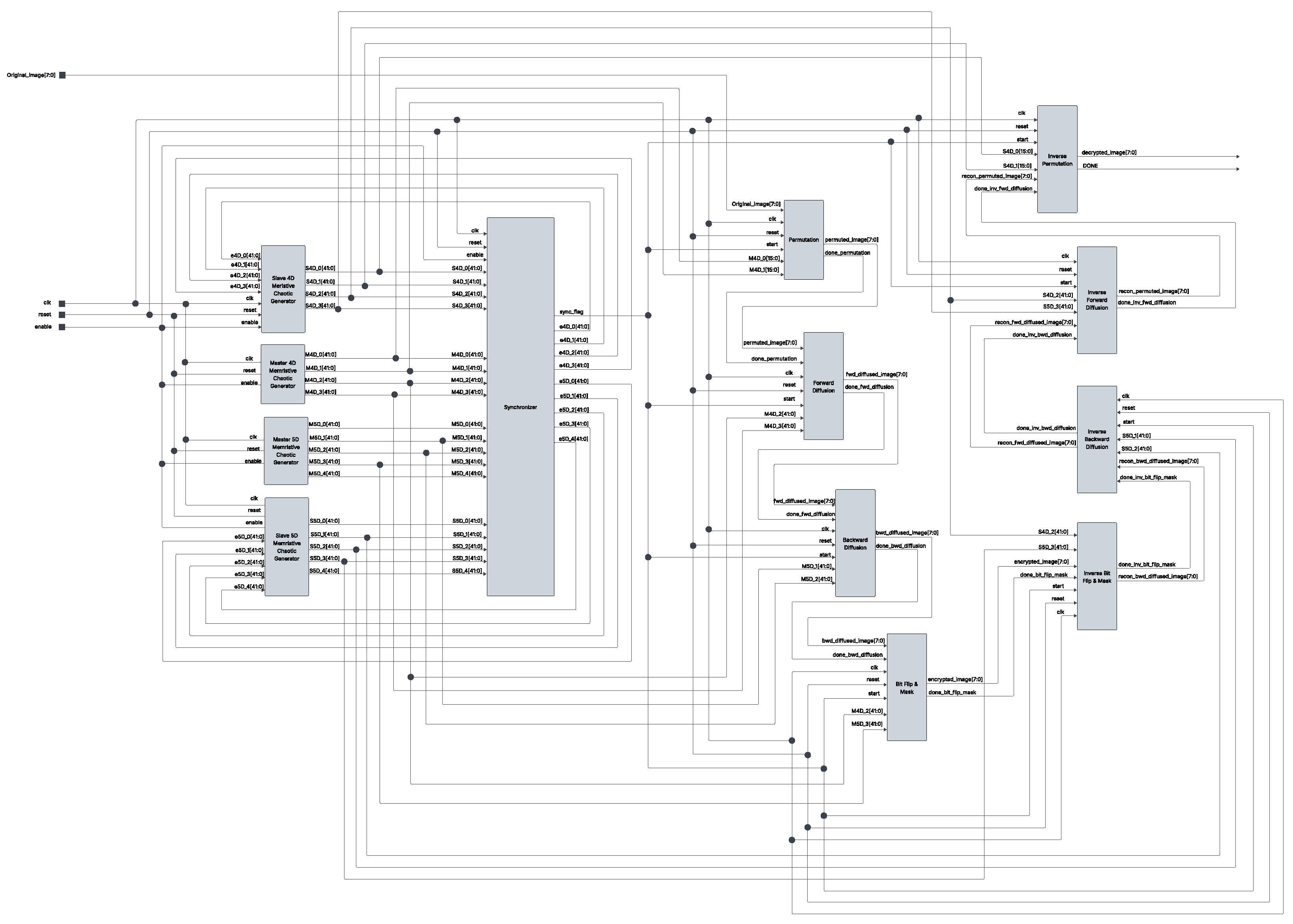
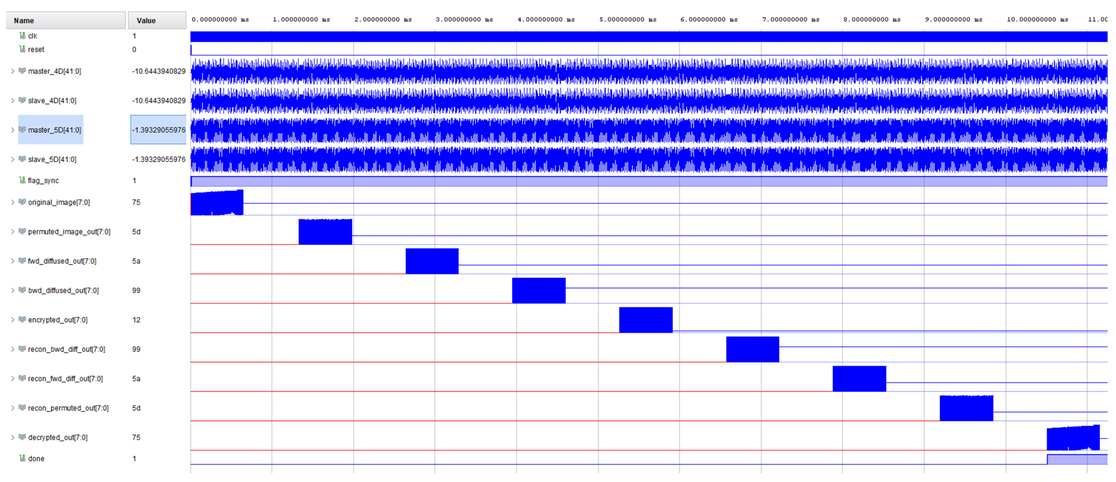
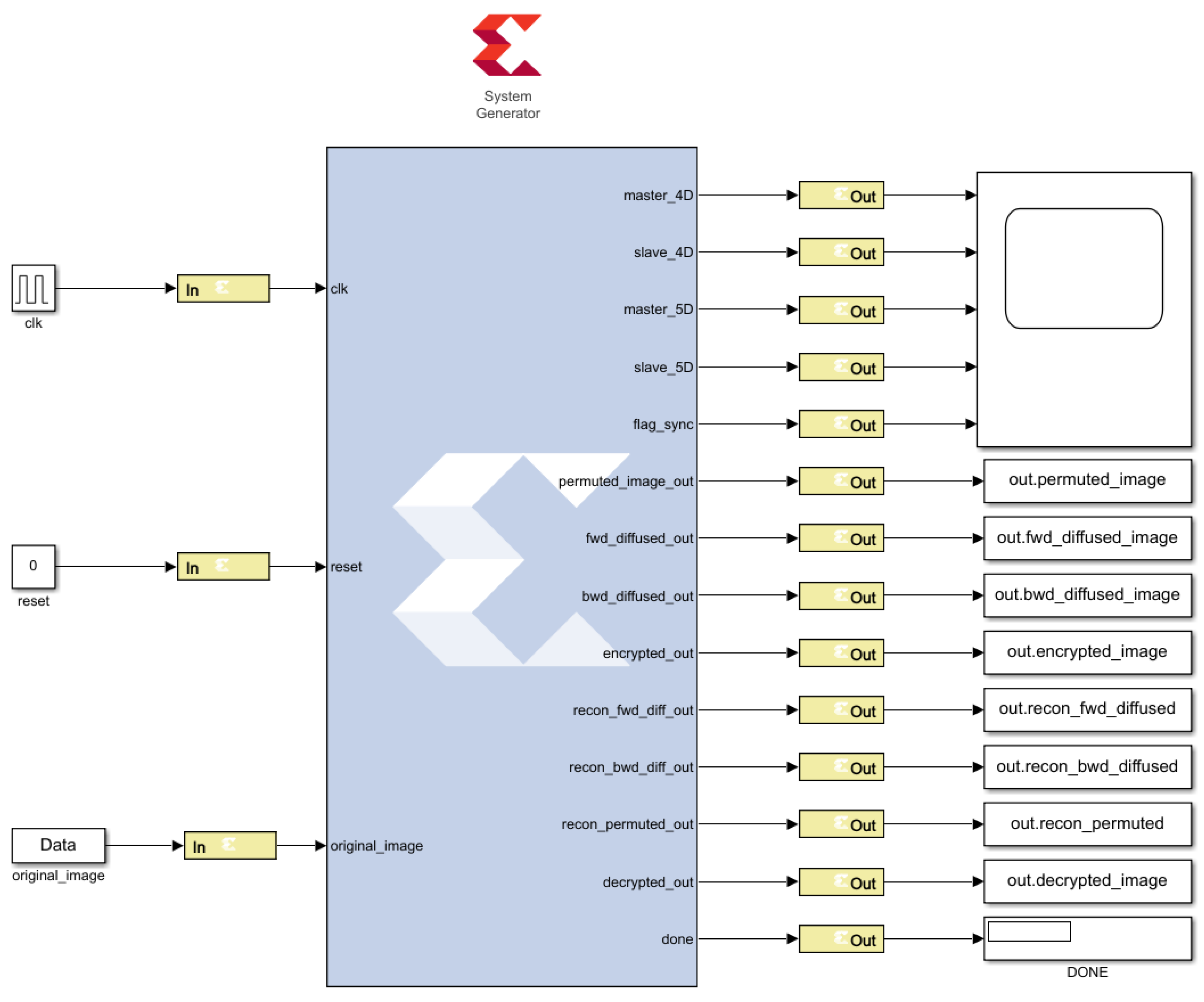
5. FPGA Implementation of Secure Image Transmission System

Figure 9 shows the high-level architecture of the FPGA implementation of the proposed image transmission system that is based on the 4D and 5D fractional-order memristive systems. The implementation is modularized into 13 dedicated hardware blocks that operate in a pipelined fashion. All modules are synchronized using global clock and reset signals to ensure deterministic behavior and reliable timing across the encryption and decryption processes. The master and slave chaotic generators are realized using VHDL implementation of the EFORK numerical method as shown in Figure 10. The parameters of the dynamical system, initial conditions, observer gains, h α , and coefficients and weights of EFORK are pre-computed and stored as constant values of 42 bits. When the enable signal is asserted, both the 4D and 5D chaotic oscillators initiate their operation based on the EFORK numerical integration scheme. The system introduces a two-clock cycle latency to allow the initial conditions to propagate through the internal register chains and stabilize. Once this initialization is completed, the synchronizer module becomes active. This module receives state vectors from both the master and slave 4D and 5D chaotic systems and continuously evaluates their convergence. Each module of the encryption and decryption systems operates as an independent finite-state machine (FSM) consisting of two sequential processes. The first process is responsible for loading the input image stream, and the second process samples the corresponding synchronized chaotic signals and implements the algorithmic functionality of the block, using the sampled chaotic values to perform localized, data-dependent transformations.
When synchronization between the master and slave chaotic systems is established, the signal s y n c _ f l a g is asserted, which enables the FSMs of the second process in all encryption and decryption modules. These modules operate in parallel and begin by sampling the chaotic state vectors from their respective systems. The sampled values are stored in internal ROMs for deterministic access during the cryptographic transformations. However, these FSMs do not immediately proceed to execute their core operations. Instead, they enter a standby state, awaiting the appropriate transition signals. In parallel, the permutation module initiates its first FSM process by sequentially loading 8-bit grayscale pixel values from the original image. Simultaneously, it uses two sampled state variables from the 4D master chaotic system to construct a dynamic permutation map. This map is generated on-the-fly to shuffle pixel positions. Once the entire image has been loaded, the FSM transitions to its next state, and executes the permutation process through dynamic index mapping. The completion of this stage is indicated by the control signal p e r m u t a t i o n _ d o n e , which triggers the forward diffusion module, specifically the FSM of its first process. This FSM begins by loading the permuted image pixels. Once loading is complete the second FSM process accesses pre-sampled 4D chaotic signals from ROM and applies the forward diffusion algorithm, which involves pixel-wise bit-rotation, XOR feedback propagation, and nonlinear transformations.
Following the completion of the forward diffusion phase, the control signal d o n e _ f w d _ d i f f u s i o n is asserted, and the first process of the backward diffusion module begins with loading the forward diffused pixels into its internal registers. Once the loading phase completes, the waiting FSM of the second process initiates the core backward diffusion logic using the previously stored sampled chaotic signals. Once backward diffusion completes successfully, the module asserts a d o n e _ b w d _ d i f f u s i o n signal, which is used as a handshake to trigger the loading of the backward diffused image in the bit flip and mask module. After the image is completely loaded, the FSM of the second process in the bit flip and mask module transitions to begin executing the final encryption stages. The module uses four sampled values from the 4D and 5D chaotic state vectors to dynamically determine specific bit positions to flip within each pixel. These positions are computed as described in Equation (54), and are further nonlinearly mapped using Equation (55) to diversify flipping patterns. Finally, the intermediate encrypted image is masked by bitwise XOR of each pixel with a nonlinear, position-variant chaotic mask, derived from the product of the corresponding 4D and 5D chaotic state variables, as formulated in Equation (57). This masking operation introduces a final layer of confusion, further obfuscating the statistical structure of the plaintext and completing the encryption pipeline. Upon successful masking, the control signal d o n e _ b i t _ f l i p _ m a s k is asserted, triggering the inverse bit-flip and mask module to begin loading the encrypted image. The decryption process then follows an inverse flow that mirrors the encryption stages, but in reverse order using the synchronized slave systems until D O N E is asserted. Each decryption module is triggered sequentially through handshaking control signals to ensure correct data flow across the pipeline. Figure 11 presents the simulation results of the proposed image transmission system, as implemented and tested in the Xilinx Vivado Design Suite. The results correspond to the processing of a 256 × 256 image and shows each stage of the encryption and decryption pipeline. Specifically, the figure demonstrates the original image signal, the permuted image signal, the forward diffused and backward diffused image signals, the final encrypted image signal, and the corresponding reversed intermediate stages through to the fully decrypted image signal. Figure 12 presents the hardware co-simulation block of the complete system, while Figure 13 provides a visual comparison between the original, encrypted, and decrypted images. The encrypted image shows a noise-like, snowflake pattern, while the decrypted image confirms accurate and complete recovery. Table 1 and Table 2 present the resource utilization analysis of the complete secure image transmission system and a detailed module-wise breakdown, respectively, targeting the Xilinx Artix-7 AC701 FPGA (AMD, Santa Clara, CA, USA) development board (device: XC7A200TFBG676-2). The reported implementation metrics were obtained using the Vivado Design Suite 2020.2 on a system configured with an Intel Core i7-7820HQ CPU (4 cores, 8 threads, 2.9 GHz base frequency, up to 3.9 GHz turbo), 64 GB DDR4 RAM (2400 MHz), Intel HD Graphics 630, and 932 GB SSD storage, running Windows 10 Pro (64-bit).

6. Security Analysis

To assess the effectiveness of the encryption scheme in decorrelating image data, we performed correlation analysis for both grayscale and RGB images on a pixel-wise basis. Specifically, the encrypted and original images were reshaped into N × 3 matrices for RGB image, and the Pearson correlation coefficients were computed using Matlab R2020b c o r r function. For the grayscale image, a scalar correlation coefficient was calculated by reshaping the images into N × 1 vectors. The results are presented in Table 3.
Additionally, to assess the statistical randomness of the encrypted images, Shannon entropy analysis was performed. For a truly random 8-bit image, the theoretical entropy value is 8. Higher entropy values reflect stronger resistance against statistical and entropy-based attacks. In the case of grayscale images, a single entropy value was computed. For RGB images, entropy was evaluated independently for each of the red, green, and blue channels, as well as collectively across all three channels. The resulting values are summarized in Table 4.
The robustness of the proposed image transmission system against occlusion attacks is tested by cropping some portion of the encrypted image, and the corrupted images were then subjected to the decryption process. Despite the significant loss of encrypted data, the decryption process was able to partially recover the structural content of the original image as shown in Figure 14.
Additionally, we performed noise attack tests to evaluate the system’s resilience against channel disturbances and data corruption. Two types of noise were introduced into the encrypted images: salt and pepper noise and Gaussian noise to simulate realistic transmission errors and potential adversarial disruptions. For each noise type, multiple intensity levels were applied to assess the degradation impact on the decrypted output. Despite the presence of significant noise, the decryption process was able to recover perceptible structural content of the original image, which demonstrates the robustness of the proposed system. Figure 15 and Figure 16 present the results of the noise attack tests under varying noise intensities using salt and pepper noise and Gaussian noise, respectively. Differential attack resistance of the proposed system is quantified using two widely accepted metrics: the number of pixels change rate (NPCR) and the unified average changing intensity (UACI). These metrics evaluate the algorithm’s sensitivity to minimal changes in the input, specifically by measuring how significantly the ciphertext varies when a single pixel in the plaintext is altered. Given two cipher images C 1 ( i , j ) and C 2 ( i , j ) that differ due to a one-pixel modification in the original image, NPCR and UACI are defined as according to Equations (57) and (58), respectively,
N P C R = 1 M × N i = 1 M j = 1 N D ( i , j ) × 100 % , where D ( i , j ) = 1 , if C 1 ( i , j ) C 2 ( i , j ) , 0 , otherwise ,
UACI = 1 M × N i = 1 M j = 1 N | C 1 ( i , j ) C 2 ( i , j ) | 255 × 100 % .
An ideal encrypted image exhibits NPCR values approaching 99.6094 and UACI values near 33.4635, which indicates strong diffusion and confusion properties of the encryption [57]. In this study, the proposed system achieved an NPCR value of 99.9776 and a UACI of 33.4154 with average values of 99.55 and 33.4154, respectively, which demonstrates high sensitivity to input changes and robustness against differential attacks.
Finally, we computed the key space of the proposed system, which is an important measure to evaluate the resistance of the encryption algorithm to brute-force attacks. The memristive 4D and 5D synchronized chaotic systems collectively consist of 9 initial conditions, 12 system parameters, 2 fractional-order values, and 9 observer gain values. All parameters are represented using 42-bit floating-point precision, resulting in a total key space of 2 1344 . This extremely large key space ensures strong protection against brute-force attacks, thereby reinforcing the cryptographic strength of the proposed design.

7. Discussion

We compare the results and performance evaluation of the proposed system with other related studies, as presented in Table 5, Table 6 and Table 7. The comparison shows that our approach relatively outperforms existing systems in several key aspects, particularly in terms of correlation reduction, entropy maximization, and efficient hardware resource consumption. These metrics are critical in evaluating the cryptographic strength and practical feasibility of real-time secure image transmission systems, especially those deployed on FPGA platforms. While the proposed architecture is DSP-intensive, primarily due to the inclusion of four distinct fractional-order chaotic oscillator modules, this design choice enables a considerable reduction in LUT and FF usage. It also enhances the randomness and diffusion characteristics of the generated keystreams, resulting in near-zero correlation with original images and entropy values approaching the ideal limit. This trade-off is justified within the context of modern FPGAs, which typically offer ample DSP slices compared to other resources. The image transmission system designed in this study is based on a commensurate fractional-order system, where all the differential equations in both the master and slave systems share the same fractional-order. Commensurate systems are often easier to synchronize and implement than incommensurate systems, particularly in hardware, due to their stability and deterministic behavior [58]. However, this structure imposes constraints on the flexibility and complexity of the system, potentially limiting the key space and overall security. To overcome these limitations, future work will investigate the implementation of incommensurate fractional-order memristive chaotic systems, where different equations within the same system can have distinct fractional orders. This approach will introduce additional dynamic complexity and unpredictability, leading to an expanded key space and stronger resistance to cryptanalytic attacks. Furthermore, we also aim to explore the implementation of incommensurate non-identical systems, where the master and slave systems differ not only in fractional order, but also in their system’s parameters. Such configurations will significantly increase the difficulty of synchronization for an attacker, thereby enhancing security.

8. Conclusions

In this investigation, a complete FPGA-based secure image transmission system was developed, using synchronized 4D and 5D memristive chaotic oscillators for encryption and decryption. The system was implemented and validated on the Xilinx Artix-7 AC701 FPGA development board. The encryption algorithm comprises a multi-stage transformation pipeline including dynamic permutation of pixel positions, bidirectional diffusion, targeted bit-flipping, and nonlinear chaotic masking. Each stage is independently driven by pseudo-random sequences derived from the real-time output of the synchronized hyperchaotic systems, which was initially analyzed using bifurcation diagrams and Lyapunov exponent spectrum analysis. To ensure hardware efficiency and real-time performance, chaotic oscillators were numerically integrated using the explicit fractional-order Runge–Kutta method, with all system parameters and initial conditions implemented with 42-bit precision. The 4D and 5D master-slave pairs were coupled through Hamiltonian and observer-based synchronization techniques, allowing both the transmitter and receiver to generate identical chaotic sequences for secure key recovery. The entire system was modularized into pipelined hardware blocks on the FPGA, with synchronous control logic ensuring accurate data flow between encryption and decryption modules. Extensive testing demonstrated the system’s robustness against common cryptanalytic attacks, including differential, occlusion, and noise-based attacks. Statistical metric such as an entropy of 7.9991 and a near-zero correlation of 6.1081 × 10 5 further validated the high randomness and unpredictability of the encrypted outputs. The encryption scheme also exhibited strong resistance to differential analysis, with an NPCR of 99.9776%, a UACI of 33.4154%, and a key space of 2 1344 , which shows its suitability for secure image transmission. The practical implications of this work are significant, the system achieve real-time secure image encryption, making it suitable for privacy-critical applications such as telemedicine, military surveillance, remote sensing, and intelligent transportation systems. The integration of high-dimensional memristive chaotic dynamics bridges the gap between theoretical chaos-based cryptography and real-world hardware realization, laying the groundwork for adaptive, application-specific encryption systems. Furthermore, its robustness against noise, occlusion, and differential attacks supports secure communication even in degraded or hostile transmission environments. This makes the system a strong candidate for next-generation hardware cryptosystems in edge computing and mobile communication infrastructures. Future investigations will focus on extending the current design to incommensurate fractional-order systems, where each state may operate with a distinct fractional order; non-identical master–slave synchronization schemes; hardware resource optimization; and parameter optimization of the memristive-based chaotic systems. Furthermore, a comprehensive cryptanalysis of the image transmission system will be undertaken to strengthen its security evaluation.

Author Contributions

Conceptualization, J.-C.N.-P., O.-M.A., V.-A.A., Y.S.-I. and E.T.-C.; methodology, J.-C.N.-P., O.-M.A., V.-A.A. and E.T.-C.; software, O.-M.A. and Y.S.-I.; validation, J.-C.N.-P., V.-A.A. and E.T.-C.; formal analysis, J.-C.N.-P., O.-M.A., V.-A.A., Y.S.-I. and E.T.-C.; investigation, J.-C.N.-P., O.-M.A. and V.-A.A.; resources, J.-C.N.-P.; writing—original draft preparation, J.-C.N.-P., O.-M.A., V.-A.A. and Y.S.-I.; writing—review and editing, J.-C.N.-P., O.-M.A., V.-A.A. and Y.S.-I.; visualization, O.-M.A. and Y.S.-I.; supervision, V.-A.A. and J.-C.N.-P.; project administration, J.-C.N.-P.; funding acquisition, J.-C.N.-P. All authors have read and agreed to the published version of the manuscript.

Funding

The authors wish to thank the Instituto Politecnico Nacional for its support provided through the project SIP-20251203.

Data Availability Statement

Data is contained within the article.

Conflicts of Interest

The authors declare no conflicts of interest.

Abbreviations

The following abbreviations are used in this manuscript:
AMAnalog multiplier
BRAMBlock random access memory
BUFGGlobal clock buffer
DSPDigital signal processor
EFORKExplicit fractional-order Runge–Kutta
FCFractional calculus
FFFlip flop
FOCFractional-order capacitor
FPGAField programmable gate array
FSMFinite-state machine
HDLHardware description language
IOInput–output
LUTLook up table
N/ANot available
PQCPost-quantum cryptography
RGBRed green blue
RSARivest–Shamir–Adleman
VHDLVery high-speed integrated circuit hardware description language

References

  1. Ye, C.; Tan, S.; Wang, J.; Shi, L.; Zuo, Q.; Feng, W. Social Image Security with Encryption and Watermarking in Hybrid Domains. Entropy 2025, 27, 276. [Google Scholar] [CrossRef]
  2. Zhang, H.; Zhang, G. Review of Research on Storage Development. Scalable Comput. Pract. Exp. 2021, 22, 365–385. [Google Scholar] [CrossRef]
  3. Adeyemi, V.A.; Tlelo-Cuautle, E.; Sandoval-Ibarra, Y.; Nuñez-Perez, J.C. FPGA Implementation of Parameter-Switching Scheme to Stabilize Chaos in Fractional Spherical Systems and Usage in Secure Image Transmission. Fractal Fract. 2023, 7, 440. [Google Scholar] [CrossRef]
  4. Hamidouche, B.; Guesmi, K.; Essounbouli, N. Mastering chaos: A review. Annu. Rev. Control 2024, 58, 100966. [Google Scholar] [CrossRef]
  5. Montero-Canela, R.; Zambrano-Serrano, E.; Tamariz-Flores, E.I.; Muñoz-Pacheco, J.M.; Torrealba-Meléndez, R. Fractional chaos based-cryptosystem for generating encryption keys in Ad Hoc networks. Ad Hoc Netw. 2020, 97, 102005. [Google Scholar] [CrossRef]
  6. Lai, Q.; Yang, L.; Liu, Y. Design and realization of discrete memristive hyperchaotic map with application in image encryption. Chaos Solitons Fractals 2022, 165, 112781. [Google Scholar] [CrossRef]
  7. Boutros, A.; Betz, V. FPGA Architecture: Principles and Progression. IEEE Circuits Syst. Mag. 2021, 21, 4–29. [Google Scholar] [CrossRef]
  8. Pan, G.; Li, C.; Liu, W.; Xue, Y.; Qi, X. Countless coexisting chaotic attractors: From system construction to FPGA-based observation. Chaos Solitons Fractals 2025, 198, 116610. [Google Scholar] [CrossRef]
  9. Almutairi, N.; Saber, S. Existence of chaos and the approximate solution of the Lorenz–Lü–Chen system with the Caputo fractional operator. AIP Adv. 2024, 14, 015112. [Google Scholar] [CrossRef]
  10. Clemente-López, D.; Munoz-Pacheco, J.M.; de Jesus Rangel-Magdaleno, J. A Review of the Digital Implementation of Continuous-Time Fractional-Order Chaotic Systems Using FPGAs and Embedded Hardware. Arch. Comput. Methods Eng. 2023, 30, 951–983. [Google Scholar] [CrossRef]
  11. Zhu, H.; Liu, W.; Sun, K.; Wang, H. Sine-modulation Discrete Memristor Chaotic Map and Its Applications. Nonlinear Dyn. 2025. [Google Scholar] [CrossRef]
  12. Bao, B.; Rong, K.; Li, H.; Li, K.; Hua, Z.; Zhang, X. Memristor-Coupled Logistic Hyperchaotic Map. IEEE Trans. Circuits Syst. II Express Briefs 2021, 68, 2992–2996. [Google Scholar] [CrossRef]
  13. Tang, J.; Pan, X.; Chen, X.; Jiang, B.; Li, X.; Pan, J.; Qu, H.; Huang, Z.; Wang, P.; Duan, J.; et al. Flexible Memristor Based on Lead-Free Cs 2 AgBiBr 6 Perovskite for Artificial Nociceptors and Information Security. Adv. Funct. Mater. 2025, 35, 2412375. [Google Scholar] [CrossRef]
  14. Ye, J.; Chen, B.; Xu, N.; Zhou, J.; Mu, R.; Du, C.; Lu, W.D. A Non-Linear Partial Differential Equation Solver Based on Analog Memristor Crossbar Arrays. IEEE J. Electron Devices Soc. 2025, 13, 477–484. [Google Scholar] [CrossRef]
  15. Fatemieh, S.E.; Bagheralmoosavi, B.; Reshadinezhad, M.R. Energy-efficient and fast memristor-based serial multipliers applicable in image processing. Results Eng. 2025, 25, 104013. [Google Scholar] [CrossRef]
  16. Ismail, M.; Na, H.; Rasheed, M.; Mahata, C.; Kim, Y.; Kim, S. Synaptic metaplasticity and associative learning in low-power neuromorphic computing using W-diffused BaTiO3 memristors. Nano Energy 2025, 142, 111276. [Google Scholar] [CrossRef]
  17. Qian, K.; Xiao, Y.; Wei, Y.; Liu, D.; Wang, Q.; Feng, W. A Robust Memristor-Enhanced Polynomial Hyper-Chaotic Map and Its Multi-Channel Image Encryption Application. Micromachines 2023, 14, 2090. [Google Scholar] [CrossRef]
  18. Yu, F.; Zhang, S.; Su, D.; Wu, Y.; Gracia, Y.M.; Yin, H. Dynamic Analysis and Implementation of FPGA for a New 4D Fractional-Order Memristive Hopfield Neural Network. Fractal Fract. 2025, 9, 115. [Google Scholar] [CrossRef]
  19. Hong, Q.; Jiang, H.; Xiao, P.; Du, S.; Li, T. A Parallel Computing Scheme Utilizing Memristor Crossbars for Fast Corner Detection and Rotation Invariance in the ORB Algorithm. IEEE Trans. Comput. 2025, 74, 996–1010. [Google Scholar] [CrossRef]
  20. Xiao, P.; Fang, J.; Wei, Z.; Dong, Y.; Du, S.; Wen, S.; Hong, Q. A Riccati Matrix Equation Solver Design Based Neurodynamics Method and Its Application. IEEE Trans. Autom. Sci. Eng. 2025, 22, 15163–15176. [Google Scholar] [CrossRef]
  21. Gokyildirim, A.; Calgan, H.; Demirtas, M. Fractional-Order sliding mode control of a 4D memristive chaotic system. J. Vib. Control 2024, 30, 1604–1620. [Google Scholar] [CrossRef]
  22. Lai, Q.; Zhu, C.; Qin, M.; Wan, Z. Complex dynamics and encryption application of a 3D dual-memristor oscillatory hyperchaotic map. Math. Comput. Simul. 2025, 236, 270–283. [Google Scholar] [CrossRef]
  23. Sah, M.; Jin, P.; Wang, G.; Yuan, F.; Fu, H. The Integral Role of Coupling Memristors in Complex Firing Patterns. Int. J. Bifurc. Chaos 2025, 35, 2530022. [Google Scholar] [CrossRef]
  24. Kundale, S.S.; Kamble, G.U.; Patil, P.P.; Patil, S.L.; Rokade, K.A.; Khot, A.C.; Nirmal, K.A.; Kamat, R.K.; Kim, K.H.; An, H.M.; et al. Review of Electrochemically Synthesized Resistive Switching Devices: Memory Storage, Neuromorphic Computing, and Sensing Applications. Nanomaterials 2023, 13, 1879. [Google Scholar] [CrossRef] [PubMed]
  25. Zhong, Y.; Tang, J.; Li, X.; Gao, B.; Qian, H.; Wu, H. Dynamic memristor-based reservoir computing for high-efficiency temporal signal processing. Nat. Commun. 2021, 12, 408. [Google Scholar] [CrossRef]
  26. Zhang, G.; Qin, J.; Zhang, Y.; Gong, G.; Xiong, Z.; Ma, X.; Lv, Z.; Zhou, Y.; Han, S. Functional Materials for Memristor-Based Reservoir Computing: Dynamics and Applications. Adv. Funct. Mater. 2023, 33, 2302929. [Google Scholar] [CrossRef]
  27. Cao, J.; Zhang, X.; Cheng, H.; Qiu, J.; Liu, X.; Wang, M.; Liu, Q. Emerging dynamic memristors for neuromorphic reservoir computing. Nanoscale 2022, 14, 289–298. [Google Scholar] [CrossRef]
  28. Gokyildirim, A.; Yesil, A.; Babacan, Y. Implementation of a memristor-based 4D chaotic oscillator and its nonlinear control. Analog. Integr. Circuits Signal Process. 2022, 110, 91–104. [Google Scholar] [CrossRef]
  29. Machado, J.T.; Kiryakova, V.; Mainardi, F. Recent history of fractional calculus. Commun. Nonlinear Sci. Numer. Simul. 2011, 16, 1140–1153. [Google Scholar] [CrossRef]
  30. İbrahim Ethem Saçu. Effects of high-order interactions on synchronization of a fractional-order neural system. Cogn. Neurodyn. 2024, 18, 1877–1893. [Google Scholar] [CrossRef]
  31. Abu-Shady, M.; Kaabar, M.K.A. A Generalized Definition of the Fractional Derivative with Applications. Math. Probl. Eng. 2021, 2021, 1–9. [Google Scholar] [CrossRef]
  32. Albadarneh, R.B.; Batiha, I.M.; Adwai, A.; Tahat, N.; Alomari, A.K. Numerical approach of riemann-liouville fractional derivative operator. Int. J. Electr. Comput. Eng. (IJECE) 2021, 11, 5367. [Google Scholar] [CrossRef]
  33. Sousa, J.V.D.C.; de Oliveira, E.C. On the Ψ-Hilfer fractional derivative. Commun. Nonlinear Sci. Numer. Simul. 2018, 60, 72–91. [Google Scholar] [CrossRef]
  34. Ma, L.; Li, C. On Hadamard Fractional Calculus. Fractals 2017, 25, 1750033. [Google Scholar] [CrossRef]
  35. Tarasov, V.E. General Fractional Calculus in Multi-Dimensional Space: Riesz Form. Mathematics 2023, 11, 1651. [Google Scholar] [CrossRef]
  36. Raza, N.; Raza, A.; Ullah, M.A.; Gómez-Aguilar, J.F. Modeling and investigating the spread of COVID-19 dynamics with Atangana-Baleanu fractional derivative: A numerical prospective. Phys. Scr. 2024, 99, 035255. [Google Scholar] [CrossRef]
  37. Jin, B. Fractional Differential Equations; Springer International Publishing: Berlin/Heidelberg, Germany, 2021; Volume 206. [Google Scholar] [CrossRef]
  38. Baliarsingh, P.; Nayak, L. Fractional Derivatives with Variable Memory. Iran. J. Sci. Technol. Trans. A Sci. 2022, 46, 849–857. [Google Scholar] [CrossRef]
  39. Lekshmi, A.S.; Balakumar, V. Numerical investigation of fractional order chaotic systems using a new modified Runge-Kutta method. Phys. Scr. 2024, 99, 105225. [Google Scholar] [CrossRef]
  40. Ghoreishi, F.; Ghaffari, R.; Saad, N. Fractional Order Runge–Kutta Methods. Fractal Fract. 2023, 7, 245. [Google Scholar] [CrossRef]
  41. Xu, S.; Wang, X.; Ye, X. A new fractional-order chaos system of Hopfield neural network and its application in image encryption. Chaos Solitons Fractals 2022, 157, 111889. [Google Scholar] [CrossRef]
  42. Al-Barakati, A.A.; Mesdoui, F.; Bekiros, S.; Kaçar, S.; Jahanshahi, H. A variable-order fractional memristor neural network: Secure image encryption and synchronization via a smooth and robust control approach. Chaos Solitons Fractals 2024, 186, 115135. [Google Scholar] [CrossRef]
  43. Khan, N.A.; Qureshi, M.A.; Khan, N.A. Evolving Tangent Hyperbolic memristor based 6D chaotic model with fractional order derivative: Analysis and applications. Partial Differ. Equ. Appl. Math. 2023, 7, 100505. [Google Scholar] [CrossRef]
  44. Feng, W.; Zhang, K.; Zhang, J.; Zhao, X.; Chen, Y.; Cai, B.; Zhu, Z.; Wen, H.; Ye, C. Integrating Fractional-Order Hopfield Neural Network with Differentiated Encryption: Achieving High-Performance Privacy Protection for Medical Images. Fractal Fract. 2025, 9, 426. [Google Scholar] [CrossRef]
  45. Mohamed, S.M.; Sayed, W.S.; Madian, A.H.; Radwan, A.G.; Said, L.A. An Encryption Application and FPGA Realization of a Fractional Memristive Chaotic System. Electronics 2023, 12, 1219. [Google Scholar] [CrossRef]
  46. Yousefpour, A.; Jahanshahi, H.; Munoz-Pacheco, J.M.; Bekiros, S.; Wei, Z. A fractional-order hyper-chaotic economic system with transient chaos. Chaos Solitons Fractals 2020, 130, 109400. [Google Scholar] [CrossRef]
  47. Shafiq, F.; Malik, M. Fractional Derivatives with Applications: A Review. Math. Sci. Appl. 2023, 2, 33–50. [Google Scholar]
  48. Roldán-Caballero, A.; Pérez-Cruz, J.H.; Hernández-Márquez, E.; García-Sánchez, J.R.; Ponce-Silva, M.; de Jesus Rubio, J.; Villarreal-Cervantes, M.G.; Martínez-Martínez, J.; García-Trinidad, E.; Mendoza-Chegue, A. Synchronization of a New Chaotic System Using Adaptive Control: Design and Experimental Implementation. Complexity 2023, 2023, 1–22. [Google Scholar] [CrossRef]
  49. Fujisaka, H.; Yamada, T. Stability Theory of Synchronized Motion in Coupled-Oscillator Systems. Prog. Theor. Phys. 1983, 69, 32–47. [Google Scholar] [CrossRef]
  50. Chen, L.Q.; Liu, Y.Z. An Open-Plus-Closed-Loop Approach To Synchronization of Chaotic And Hyperchaotic Maps. Int. J. Bifurc. Chaos 2002, 12, 1219–1225. [Google Scholar] [CrossRef]
  51. Hoon, Y.; Radzi, M.A.M.; Zainuri, M.A.A.M.; Zawawi, M.A.M. Shunt Active Power Filter: A Review on Phase Synchronization Control Techniques. Electronics 2019, 8, 791. [Google Scholar] [CrossRef]
  52. Li, C.; Liao, X.; wo Wong, K. Lag synchronization of hyperchaos with application to secure communications. Chaos Solitons Fractals 2005, 23, 183–193. [Google Scholar] [CrossRef]
  53. Sira-Ramírez, H.; Cruz-Hernández, C. Synchronization Of Chaotic Systems: A Generalized Hamiltonian Systems Approach. Int. J. Bifurc. Chaos 2001, 11, 1381–1395. [Google Scholar] [CrossRef]
  54. Estudillo-Valdez, M.A.; Adeyemi, V.A.; Tlelo-Cuautle, E.; Sandoval-Ibarra, Y.; Nuñez-Perez, J.C. FPGA realization of four chaotic interference cases in a terrestrial trajectory model and application in image transmission. Sci. Rep. 2023, 13, 12969. [Google Scholar] [CrossRef]
  55. Zhao, Q.; Wang, C.; Zhang, X. A universal emulator for memristor, memcapacitor, and meminductor and its chaotic circuit. Chaos Interdiscip. J. Nonlinear Sci. 2019, 29, 013141. [Google Scholar] [CrossRef]
  56. Koçak, H.; Palmer, K.J. Lyapunov Exponents and Sensitive Dependence. J. Dyn. Differ. Equ. 2010, 22, 381–398. [Google Scholar] [CrossRef]
  57. Yue, W.; Noonan, J.P.; Agaian, S. NPCR and UACI Randomness Tests for Image Encryption. J. Sel. Areas Telecommun. 2011, 1, 31–38. [Google Scholar]
  58. Liu, J.; Li, R.; Huang, D. Stability, bifurcation and characteristics of chaos in a new commensurate and incommensurate fractional-order ecological system. Math. Comput. Simul. 2025, 236, 248–269. [Google Scholar] [CrossRef]
  59. Li, Y.; Li, C.; Li, Y.; Moroz, I.; Yang, Y. A joint image encryption based on a memristive Rulkov neuron with controllable multistability and compressive sensing. Chaos Solitons Fractals 2024, 182, 114800. [Google Scholar] [CrossRef]
  60. Man, Z.; Li, J.; Di, X. Medical image encryption scheme based on self-verification matrix. IET Image Process. 2021, 15, 2787–2798. [Google Scholar] [CrossRef]
  61. Adeyemi, V.A.; Nuñez-Perez, J.C.; Ibarra, Y.S.; Perez-Pinal, F.J.; Tlelo-Cuautle, E. FPGA Realization of the Parameter-Switching Method in the Chen Oscillator and Application in Image Transmission. Symmetry 2021, 13, 923. [Google Scholar] [CrossRef]
  62. Al-Hussein, A.B.A.; Tahir, F.R.; Al-Suhail, G.A. Design and FPGA Implementation of a Hyper-Chaotic System for Real-time Secure Image Transmission. Iraqi J. Electr. Electron. Eng. 2025, 21, 55–68. [Google Scholar] [CrossRef]
  63. Abdullah, H.A.; Abdullah, H.N. FPGA implementation of color image encryption using a new chaotic map. Indones. J. Electr. Eng. Comput. Sci. 2019, 13, 129. [Google Scholar] [CrossRef]
  64. Younas, I.; Khan, M. A New Efficient Digital Image Encryption Based on Inverse Left Almost Semi Group and Lorenz Chaotic System. Entropy 2018, 20, 913. [Google Scholar] [CrossRef]
  65. Ciylan, F.; Ciylan, B.; Atak, M. FPGA-Based Chaotic Image Encryption Using Systolic Arrays. Electronics 2023, 12, 2729. [Google Scholar] [CrossRef]
  66. Yu, F.; Liu, L.; He, B.; Huang, Y.; Shi, C.; Cai, S.; Song, Y.; Du, S.; Wan, Q. Analysis and FPGA Realization of a Novel 5D Hyperchaotic Four-Wing Memristive System, Active Control Synchronization, and Secure Communication Application. Complexity 2019, 2019, 4047957. [Google Scholar] [CrossRef]
  67. Peng, X.; Zeng, Y. Image encryption application in a system for compounding self-excited and hidden attractors. Chaos Solitons Fractals 2020, 139, 110044. [Google Scholar] [CrossRef]
  68. Yu, F.; Shen, H.; Zhang, Z.; Huang, Y.; Cai, S.; Du, S. A new multi-scroll Chua’s circuit with composite hyperbolic tangent-cubic nonlinearity: Complex dynamics, Hardware implementation and Image encryption application. Integration 2021, 81, 71–83. [Google Scholar] [CrossRef]
Figure 1. Universal fractional-order memelement circuit topology. Source: Own elaboration adapted from [55].
Fractalfract 09 00506 g001
Figure 2. Universal fractional-order memristive chaotic circuit. Source: Own elaboration adapted from [55].
Fractalfract 09 00506 g002
Figure 3. Fractional order parameter analysis of 4D dynamical system (a) Bifurcation diagram; (b) Lyapunov exponent spectrum (partial enlargement). Source: own elaboration.
Fractalfract 09 00506 g003
Figure 4. Phase portrait of fractional-order 4D memristive chaotic oscillator (24) for α = 0.999999 . (a) X–Y projection; (b) X–Z projection; (c) Y–Z projection; (d) Y–W projection; (e) time-series plot; (f) 3D-plot. Source: own elaboration.
Fractalfract 09 00506 g004
Figure 5. Fractional order parameter analysis of FOMC-based dynamical system (a) Bifurcation diagram; (b) Lyapunov exponent spectrum (partial enlargement). Source: own elaboration.
Fractalfract 09 00506 g005
Figure 6. Phase portrait of fractional-order 5D memristive chaotic oscillator (27) for α = 0.999999 . (a) X–Y projection; (b) X–Z projection; (c) Y–Z projection; (d) Y–W projection; (e) time-series plot; (f) 3D-plot. Source: own elaboration.
Fractalfract 09 00506 g006
Figure 7. Master–slave synchronization of 4D memristive chaotic system. (a) Time series; (b) synchronization error. Source: own elaboration.
Fractalfract 09 00506 g007
Figure 8. Master–slave synchronization of 5D memristive chaotic system. (a) Time series; (b) synchronization error. Source: own elaboration.
Fractalfract 09 00506 g008
Figure 9. Hardware architecture of secure image transmission system based on 4D and 5D memristive chaotic oscillators. Source: own elaboration.
Fractalfract 09 00506 g009
Figure 10. Hardware architecture of explicit fractional-order Runge–Kutta method of order 2 α . Source: own elaboration.
Fractalfract 09 00506 g010
Figure 11. Hardware simulation of secure image transmission system based on 4D and 5D memristive chaotic oscillators in Vivado. Source: own elaboration. Red: Uninitialized, Blue: Signals.
Fractalfract 09 00506 g011
Figure 12. Hardware co-simulation block of secure transmission system: own elaboration.
Fractalfract 09 00506 g012
Figure 13. 256 × 256 images transmitted using 4D and 5D memristive chaotic systems. (a) Original RGB (top right) and greyscale (bottom right) images; (b) encrypted RGB (top middle) and greyscale (bottom middle) images; (c) recovered RGB (top left) and greyscale (bottom left) images. Source: own elaboration.
Fractalfract 09 00506 g013
Figure 14. Occlusion attack test results. (a) 1/4 crop (top right) and decrypted (bottom right) images; (b) 3/4 crop (top middle) and decrypted (bottom middle) images; (c) 7/8 crop (top left) and decrypted (bottom left) images. Source: own elaboration.
Fractalfract 09 00506 g014
Figure 15. Noise attack test result using salt and pepper noise. (a) 0.0001 density (top right) and decrypted (bottom right) images; (b) 0.001 density (top middle) and decrypted (bottom middle) images; (c) 0.1 density (top left) and decrypted (bottom left) images. Source: own elaboration.
Fractalfract 09 00506 g015
Figure 16. Noise attack test result using Guassian noise, (a) 0.00001 variance (top right) and decrypted (bottom right) images; (b) 0.0001 variance (top middle) and decrypted (bottom middle) images; (c) 0.0005 variance (top left) and decrypted (bottom left) images. Source: own elaboration.
Fractalfract 09 00506 g016
Table 1. Resource analysis of secure image transmission system based on 4D and 5D memristive chaotic systems. Source: own elaboration.
MetricLUTFFDSPI/OBUFGLUTRAM
(134,600)(269,200)(740)(400)(32)(46,200)
Resource16,21332525287512234
Utilization12.05%1.12%71.35%18.75%37.5%0.51%
Table 2. Module-by-module logical resource analysis of secure communication systems. Source: own elaboration.
ModuleLUT (134,600)FF (269,200)DSP (740)I/O (400)BUFG (32)LUTRAM (46,200)
Top level00075120
4D master2530368120000
4D slave2394368122000
5D master2938452142000
5D slave2809452144000
Synchronizer4273890000
Permutation159518700020
Forward diffusion22919800019
Backward diffusion21111800035
Bit flip and mask21911000043
Inverse permutation159218600020
Inverse forward diffusion1978400019
Inverse backward diffusion1178400035
Inverse bit flip and mask1108400043
Table 3. Correlation coefficients between original and encrypted images (RGB and grayscale).
Encrypted Image
RGBGrayscale
R5.6357 × 10 4 −0.0034−0.0032
Original ImageG−0.0049−0.0072−0.00579.2066 × 10 4
B3.7362 × 10 4 −4.8187 × 10 4 −6.1081 × 10 5
Table 4. Entropy values of the original and encrypted images.
RGBRGBGrayscale
Original Image7.81097.78287.16837.79637.5446
Encrypted Image7.99657.99747.99717.99917.9972
Table 5. Comparison of correlation coefficients.
ReferencesRGB ImageGreyscale Image
RedGreenBlue
This work3.7362 × 10 4 −4.8187 × 10 4 −6.1081 × 10 5 9.2066 × 10 4
[45]0.0001−0.00020.0003N/A
[59]0.0019−0.0025−0.0031N/A
[60]0.00080.0035−0.0059N/A
[61]0.03160.04980.02960.0352
Table 6. Comparison of information entropy.
ReferencesThis Work[62][63][64]
RGB7.99917.99927.99797.9971
Table 7. Comparison of implementation. N/A implies: Not Available.
ReferencesThis Work[65][66][67][68]
FPGAArtix-7Virtex-7ZYNQArtix-7ZYNQ
LUT16,21338,27323,17310,86715,978
FF3252237126,893121421,057
DSP52863N/A1620
I/O75N/A303616
HDLVHDLVerilogVerilogVerilogVHDL
AlgorithmEFORKHeunRK4RK4RK4
Disclaimer/Publisher’s Note: The statements, opinions and data contained in all publications are solely those of the individual author(s) and contributor(s) and not of MDPI and/or the editor(s). MDPI and/or the editor(s) disclaim responsibility for any injury to people or property resulting from any ideas, methods, instructions or products referred to in the content.

