1. Introduction
Nowadays, wireless communication technology demands a more reliable source medium to fulfil the requirements of broadband, IoT, data analysis, and smartphone use. For these, although the existing telecommunication infrastructure is sufficient to meet the needs of urban and suburban areas, it is not reliable in extremely rural areas or areas with no connectivity. The governments are still trying to cover all the suburban areas with minimum communication. However, a gap still exists in dense forest areas. In these cases, communication relies solely on satellite communication services. Some existing telecom infrastructures purely depend on VSAT as backhaul, where fibre or microwave backhaul is not feasible. However, even with the help of VSAT backhaul, it is not possible to develop towers to provide existing communication services. Hence, the only solution is communication through satellites. These satellite services are not very advanced in their current state. They can only be used now for SOS or emergency message services using low-earth orbit satellites. Some current devices, such as those from Apple and Samsung, can share messages over a satellite link. The Snapdragon X80 5G modem in Galaxy phones supports satellite connectivity for non-terrestrial networks. However, voice or data connectivity is still not advanced enough to work at full capacity. This field requires extensive research and deployment to deliver improved communication services to users. Satellite internet communications are now operated in the Ku-band in most areas, covering the frequency range from 12 GHz to 18 GHz. Antennas with reflectors are used in these satellite communication services [
1]. These reflector antennas help achieve high gain with a very narrow beam and low side lobe levels for point-to-point or point-to-multipoint communications. The main applications include broadband internet access and backhaul for cellular networks. The current research and development trend for Ku-band satellite internet antennas includes multiband and multi-mode operations, antenna miniaturisation, antenna materials, the use of flat panel structures, increased bandwidth, beamforming, IoT connectivity, and high-throughput facilities. Among all these recent trends, antenna miniaturisation, high gain, and beam scan capabilities are being focused on, and extensive studies are being carried out to solve the issues.
Conventional reflectors are very bulky and space-consuming when used with the feeder. To address this issue, the concept of reflectarray has been developed by researchers. Reflectarray antennas are a hybrid of phased arrays and reflectors [
2]. A reflectarray comprises a few radiators that impart a specified phase to the incident field from a feed and radiate the signal back into free space. These are very lightweight, easy to design, and can be fitted anywhere with minimal space requirements. In this way, reflectarrays are preferable over conventional reflectors for satellite communications. Several types of reflectarray antennas have been studied by J.A.Joy et al. in [
3]. These include the FSS-backed reflectarray [
4], modified Malta cross [
5], fractal-shaped reflectarray [
6], Phoenix cell [
7], spiraphase reflectarray [
8], reflectarray with the perforated dielectric substrate [
9], etc. Among them, the Phoenix cell and fractal-shaped unit cell reflectarray are the most popular due to their ease of design and analysis. In [
7], L. Moustafa developed a Phoenix cell reflectarray and demonstrated the structure performance with different ring widths at 5 GHz. Similarly, in [
10], C. Tian et al. studied a broadband reflectarray using a circular phoenix unit cell at a higher frequency range around 10 GHz. A 225-element reflectarray is designed and studied for different ring radius in the same article. Intelligent metasurfaces are also found to be an excellent option for use in the design of antennas for satellite communications [
11,
12]. In [
11], a lightweight and efficient stacked intelligent meta-surface (SIM) is mounted on a LEO satellite to achieve multi-user beamforming. Similarly, reconfigurable intelligent surfaces (RISs) are utilised in [
12] to enhance coverage in space–air–ground integrated networks. Later, the fractal concept is adapted to design reflectarray unit cells instead of square or circular ring structures. The self-similarity and space-filling properties of the fractal [
13] help to miniaturise the array structure with the required performance. Different fractal shapes, such as the Koch triangle, Minkowski fractal, and Koch square unit cells, are considered unit cells for reflectarrays. Their performances are tested in [
14] with various scaling factors and fractal iterations. A new opportunity is unlocked for fixed-size and different-size reflectarray designs with the fractal concept. Similarly, T. Bashir et al. developed a miniaturised Minkowski fractal reflectarray with a fixed-size patch [
15]. A 15 × 15 reflectarray prototype is designed and presented for fixed-beam and large-scanning capabilities. The balanced performance characteristics and ease of fractal reflectarray design draw the attention of many researchers to its use in satellite communications. Although many reflectarray designs have been proposed for satellite communications, they remain bulky and complex in design, and there is considerable scope for miniaturising these designs. Additionally, the major performance parameters must be evaluated in relation to different design parameters, and a relationship between them needs to be established. This motivated the study in the design and performance evaluation of miniaturised fractal reflectarrays and to test it in a real-time simulation environment for real-world applicability.
In this article, a similar Minkowski Fractal concept, as presented in [
6], is used as the unit cell for the design of a reflectarray in
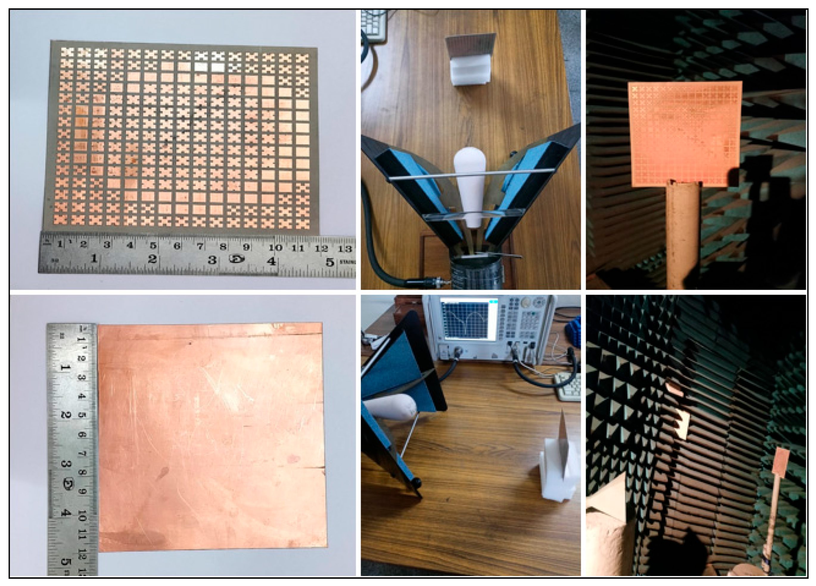
Section 2. The evaluation of performance metrics, such as gain and beam scan capabilities, is explored to the maximum extent here, with the help of sensitivity analysis of the design parameters in the same section. A wide variety of design parameter options are examined to find the best possible outcome of the fractal reflectarray. The reflectarray prototype is then fabricated, and its reflection and radiation characteristics are measured using a horn antenna as its feeder in
Section 3. After that, a comparison is made in terms of size and other performances of the proposed reflectarray with other available similar designs. The performances of the same antenna are then tested in a real-time MATLAB simulation environment in
Section 4. A satellite communication scenario is created with satellites in Low Earth Orbit (LEO), Medium Earth Orbit (MEO), and a ground station. The designed antenna is then imported and tested for interference scenarios under varying conditions and times. Ultimately, the conclusion is drawn in
Section 5, outlining the possible future applications of the design.
2. Minkowski Fractal Reflectarray Design and Its Sensitivity Analysis
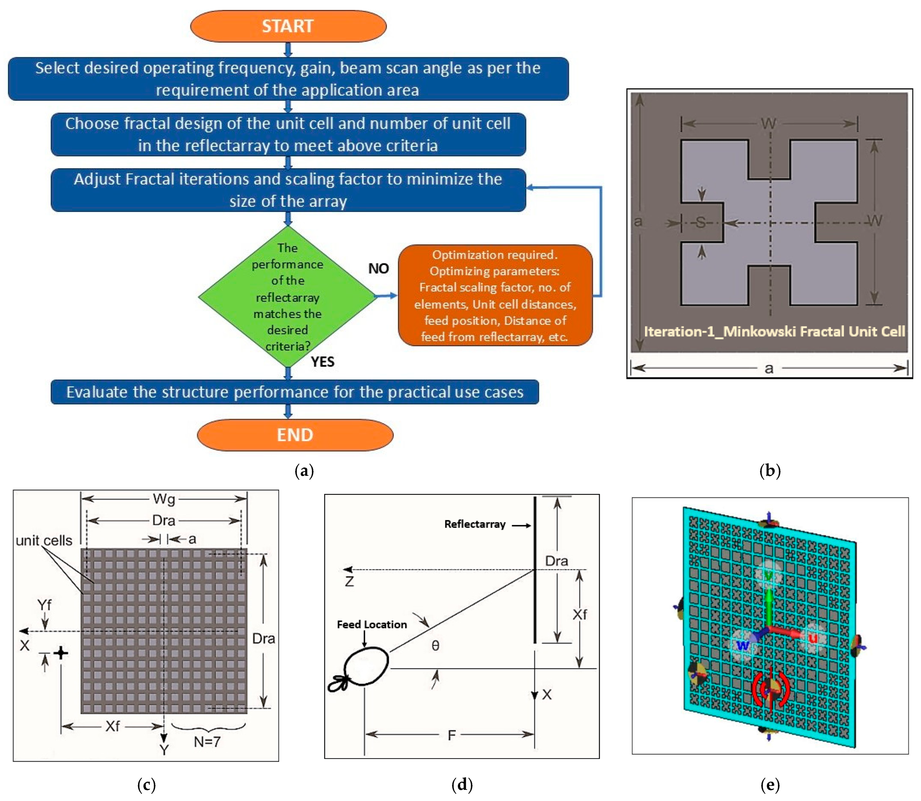
The main objective here is to design a high-gain reflectarray consisting of a Minkowski fractal unit cell with beam scanning capabilities at 12 GHz. Later, the work focuses on providing insight into the design’s maximum capabilities and its limitations for use in Ku-band satellite internet communications. Hence, initially, a simple fixed-size reflectarray with a 1st iteration Minkowski fractal unit cell [
6] and a grounded substrate is designed here. The total number of unit cell grid points is set to 15 × 15, utilising a highly efficient RO3003 substrate with an εr of 3 and a thickness of 0.5 mm to maximise the gain and other performance characteristics of the antenna. The design is considered symmetric around one axis, where one half of the reflectarray is a mirror image of the other half with respect to the X-axis. The arrangement of the individual elements, made with different scaling factors, achieves the required gain and aligns the main beam direction with the required orientation. Typically, the reflectarray is illuminated by a horn antenna as a feed. Here, a horn antenna is also considered as a source within the same design frequency range. The distance between the horn feed and reflectarray antenna is considered 50 mm at the centre of the reflectarray. Generally, the reflectarray performs better when the number of elements is seven or more in both the X-axis and Y-axis. The side lobe level will increase further if the design occurs with a number of elements less than 7. As this work involves a significant amount of simulation to determine the sensitivity of design parameters with respect to overall gain and beam scanning, to ease the process and save time, a minimum seven-element configuration is selected. The geometry of the proposed patch antenna is shown in
Figure 1.
The space-filling properties of the Minkowski fractal help reduce the overall size of the array with a fixed-size patch. Here, the miniaturisation capability of the fractal concept is fully exploited by leaving the unit cell length unchanged. The scaling factor of fractal plays an important role in the phase agility or beam scanning of the array. By carefully adjusting the scale factor of each element in the array, the main beam can be oriented towards a particular direction without changing its overall dimension.
Initially, a 15 × 15 reflectarray is designed for a centre frequency of 12 GHz. Later, the design is optimised to have a gain above 20 dB with a narrow beamwidth of 15 degrees. The beam direction of the reflectarray is fixed towards 30 degrees with respect to its normal to avoid material loss in the feeder. The feeder is placed at a distance of 50 mm with an edge tapper of −10 dB and 0.7 feed distribution efficiency. With this setup, the design is optimised, and the optimised design parameters are presented in
Table 1, along with their classifications. The parameters and their values can be mapped to the design layout in
Figure 1 to gain a better understanding of the structure.
The main feature of the reflectarray is the relationship between the beam phase and the design parameters. Thus, carefully adjusting the design parameters results in the required beam orientation. The phase shift in the reflectarray is the function of the path length difference between the incident and reflected waves. This relationship can be deduced from Equation (1). In a fractal-based reflectarray, for a fixed iteration, the scaling factor determines the resonant length of the fractal element, which in turn directly affects the phase shift. The relationship between the resonating length and fractal scaling factor can be found in Equation (2). Hence, by manipulating the scaling factor of the fractal unit cell with a fixed iteration, one can vary the phase of the element, which results in the desired beam steering of the reflectarray.
where
is the phase shift in the reflectarray,
is the wavelength of the incident wave, and
is the patch length difference between the incident and reflected wave. The patch length difference between the incident and reflected waves can be calculated from the scaling factor using the following relationship.
Here,
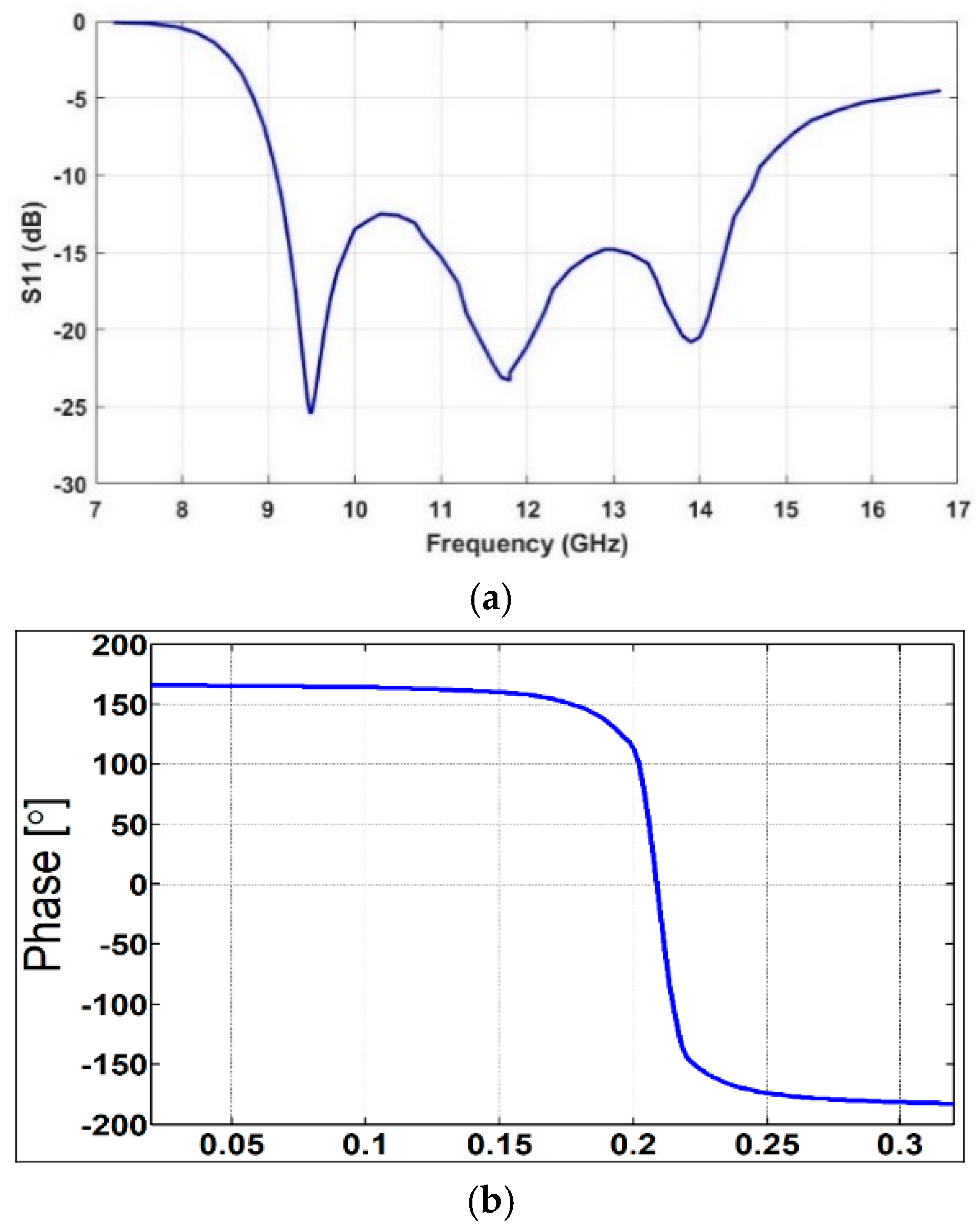
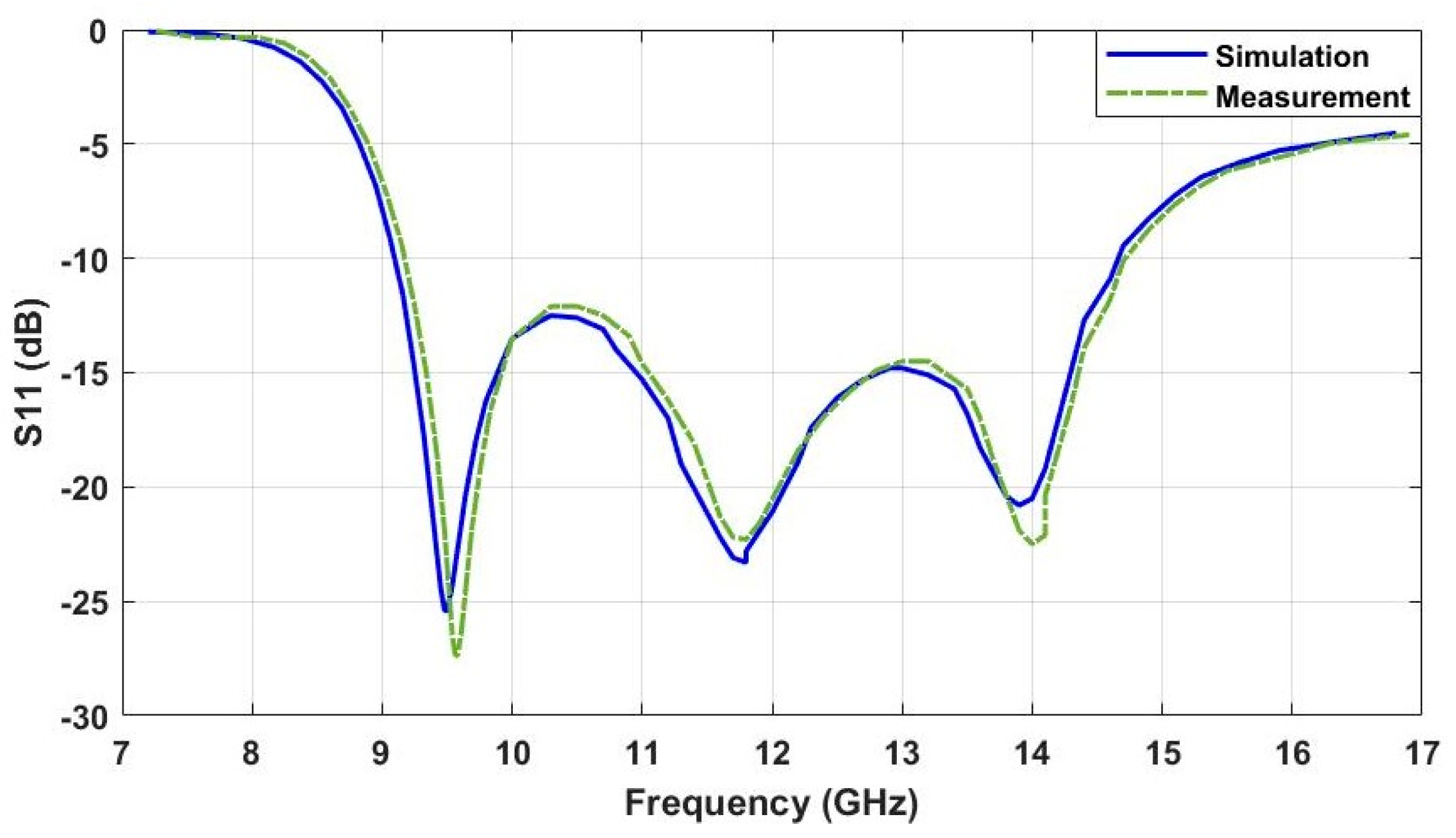
is the resonating length of the unit cell generated in the nth iteration, S is the scaling factor, and L is the straight length of the unit cell. Hence, for a fixed iteration, only by varying the scaling factor of the fractal, the difference between electrical and physical length can be varied to adjust the phase of the array. The reflection characteristics of the antenna depend on the feeder of the array. The reflection characteristics of the proposed design are shown in
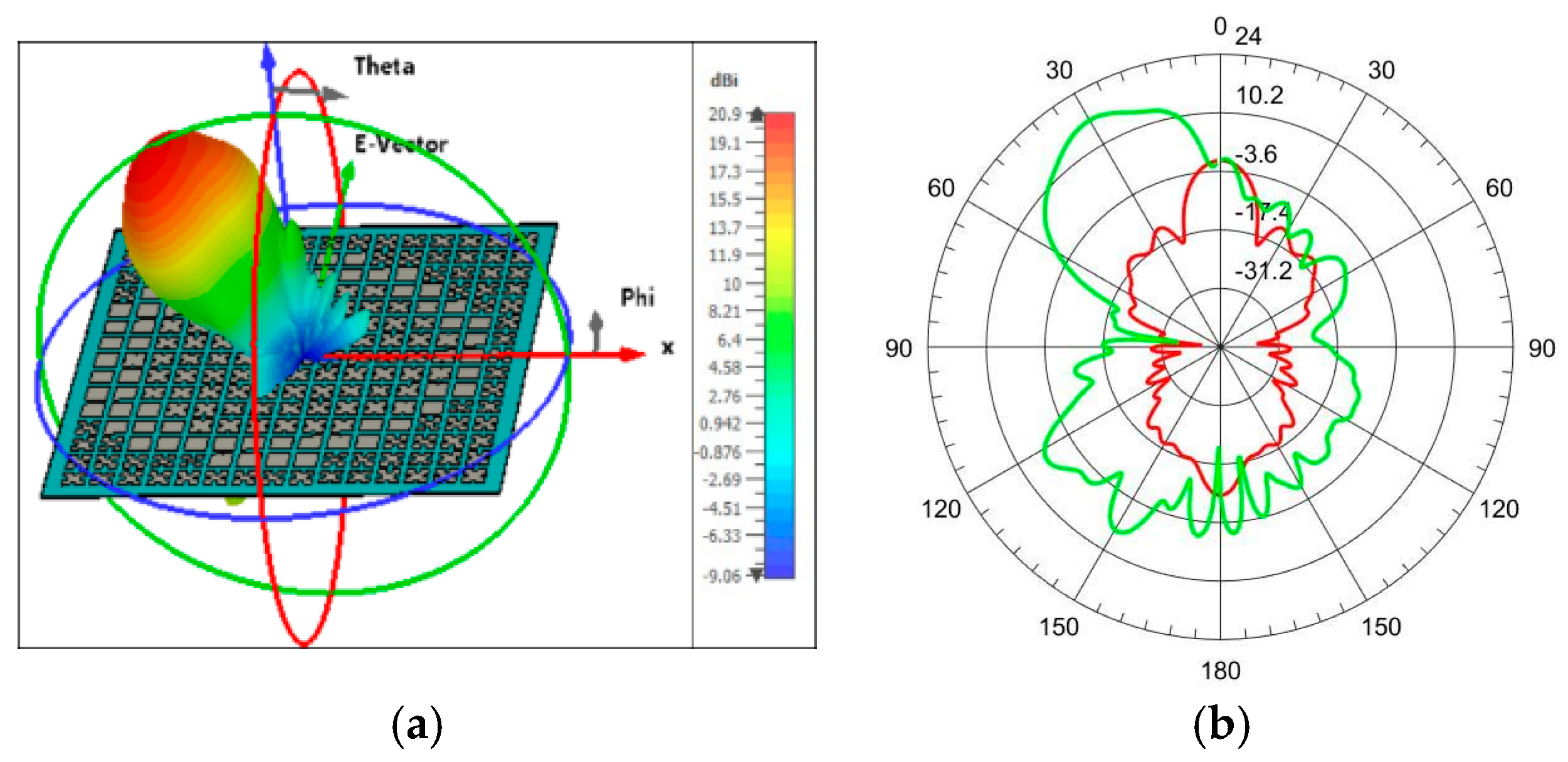
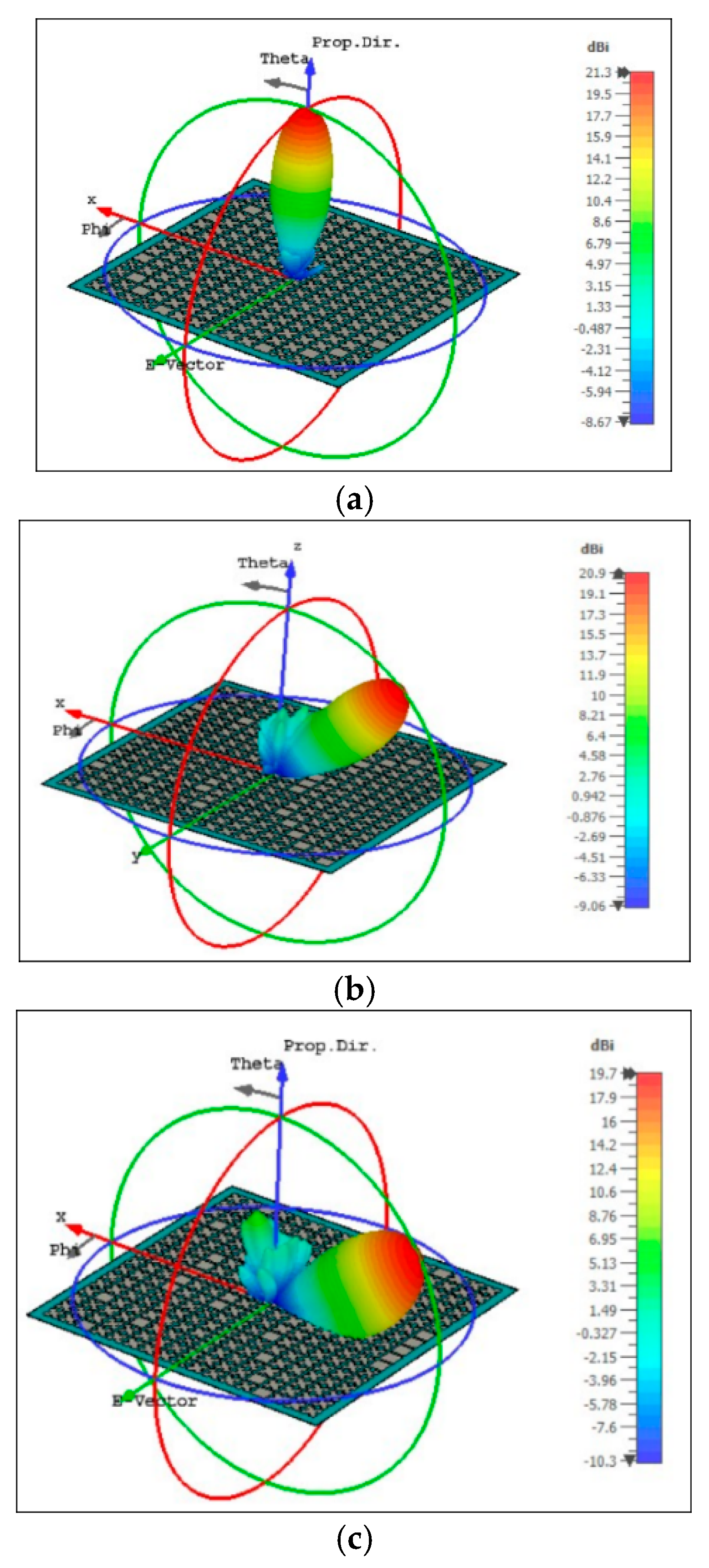
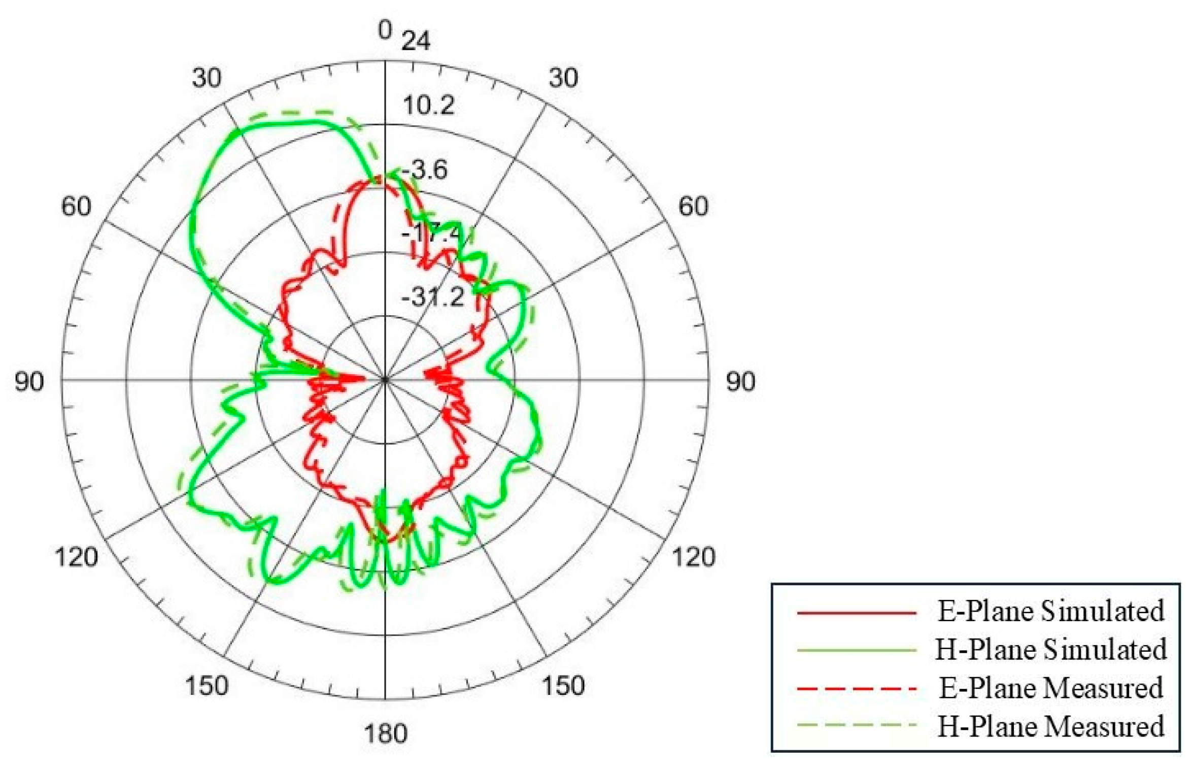
Figure 2. In the same figure, the reflection phase characteristics with respect to the fractal scaling factor are also analysed. These curves are determined from the simulation of a unit cell using the Floquet port in CST Microwave Studio. The integral equation solver in CST simulation is used to analyse the structure. With this reflection phase and scaling factor property, the phase of each element in the array is adjusted to orient the main beam towards 30 degrees, and the radiation pattern is shown in
Figure 3. From the figure, the gain of the antenna is observed to be above 20 dB with a side lobe level of less than −10 dB. From the simulation, it is observed that the gain remains relatively constant for scan angles up to 30 degrees. Above this scan angle variations, the gain will start to decrease with an increase in side lobe levels.
After designing the optimised Minkowski Fractal reflectarray structure, the evaluation of performance metrics, such as gain and beam scan capabilities, is explored to the maximum extent with the help of sensitivity analysis of the design parameters in the same section. A wide variety of design parameter options are examined to find the best possible outcome of the fractal reflectarray. The simulation software, Ansys HFSS 2015.1, offers a sensitivity analysis option, which aims to identify the most influential design parameters for a specific performance parameter. It employs a second-order derivative approach in analytics to determine the graph of the relationship between the design parameter and the performance parameter. In our case, without having prerequisites regarding the design parameters, their ranges, and the relationship between them and the performance parameters, the use of this sensitivity analysis from HFSS is not an effective approach. Hence, here, the relationship between design and performance parameters is found using the array synthesis method by exploiting the setup values of design parameters. Array synthesis is a process of designing an antenna array to achieve a desired array pattern by adjusting the individual element dimensions and their excitations. To evaluate the performance parameters for a practical scenario, the ranges of these parameters are determined. Based on these selections, the design parameters are then evaluated, and a relationship is formed among them. To find this relationship between performance and design parameters, Optimetrics from HFSS is used, where a single parameter is varied at a time while keeping all other parameters constant. After this evaluation, the values are confined to more practical and possible scenarios from a wide range of design parameters. The gain of the reflectarray usually depends on the number of elements, shape modifier, focal length, and offset feed position. The sensitivity of these design parameters is investigated with respect to the gain of the array, as shown in
Figure 4. Similarly, another important performance parameter of the array, i.e., its scanning capabilities, is also exploited with respect to the most influential design parameters, as shown in
Figure 5. A guideline for the design of reflectarray with a minimum to maximum range of gain and beam scanning is proposed in
Table 2. The beam path of the reflectarray can be changed by adjusting the phase of the individual unit cells and the position of the unit cell in the array. The phase of the individual unit cell is a function of the fractal scaling factor and fractal iteration. Hence, ultimately, by changing the fractal scaling factor with a fixed iteration, one can be able to orient the beam path of the reflectarray. The relationship between the beam scan angle and the phase of the reflectarray is given in Equation (3).
Here, is the phase at the ith element, is the free space wave number, is the distance between the feed centre to the element, and (,) is the direction of the beam.
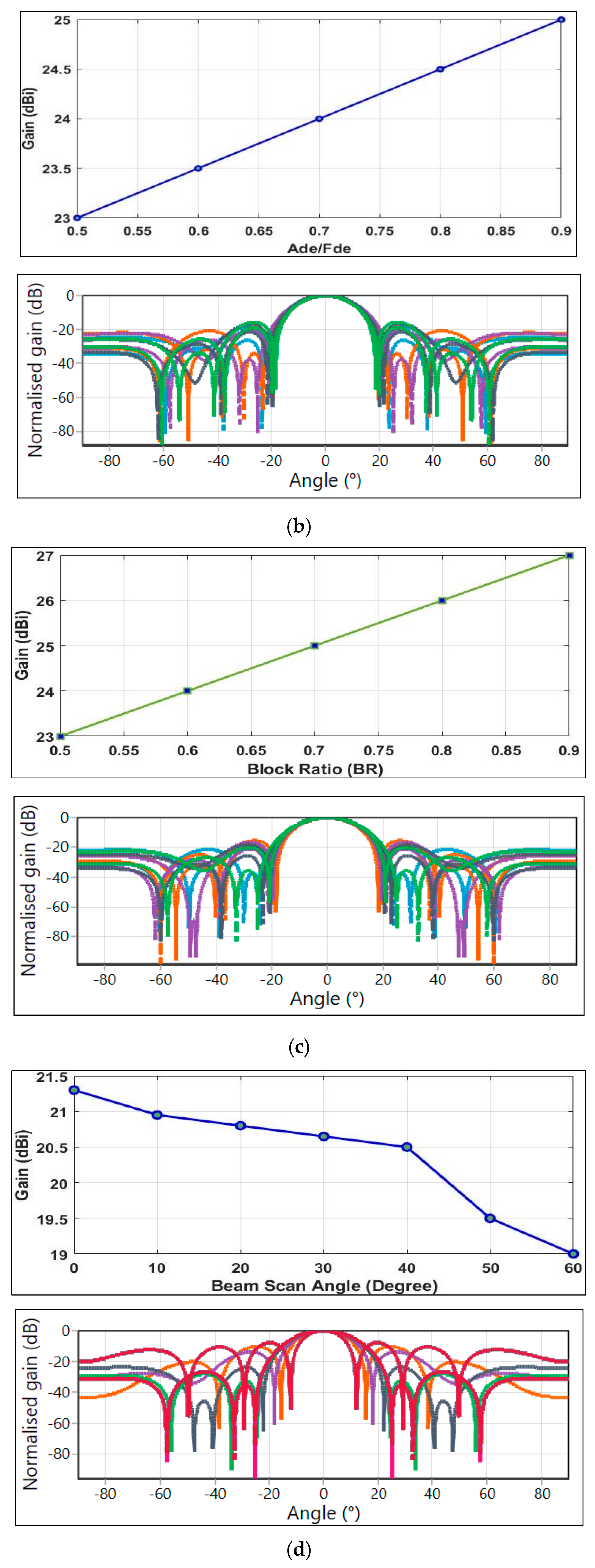
A reflectarray is desired to have high gain with narrow beam radiation patterns. Hence, these two parameters are always focused while designing any reflectarray. Thus, the effect of design parameters like the number of elements (N) in the array, Feed and Aperture Distribution Efficiency (FDe/Ade), and Block Ratio (BR, Feed Diameter to Reflectarray Diameter) over the gain of the reflectarray are plotted in
Figure 4. In the following
Figure 5, the gain is observed with respect to changes in beam scan angles. During the analysis, all other parameters are kept constant like for variations with N (Frequency of operation: 12 GHz, RO3303 Material with 0.5 mm thickness, Xf: 50 mm, a: 7.495 mm, BR: 0.2), for variation with FDe/Ade (Frequency of operation: 12 GHz, RO3303 Material with 0.5 mm thickness, Xf: 50 mm, N: 7, a: 7.495 mm, BR: 0.2), and BR (Frequency of operation: 12 GHz, RO3303 Material with 0.5 mm thickness, Xf: 50 mm, N: 7, a: 7.495 mm, FDe/Ade: 0.6). From
Figure 4, it can be observed that an increase in the number of elements of array results in an increase in the gain of the reflectarray. The normalised gain patterns for these parameter variations also confirmed the same with respect to their beamwidth changes. Similarly, the increase in FDe/ADe and BR also increases the overall gain. However, the gain variation is more in the case of changes in N rather than changes in the other three parameters. As the number of elements increases, the overall size of the reflectarray also grows, resulting in increased space requirements. Hence, for the optimal design scenario, the size of the elements N must be determined based on space availability, with high distribution efficiency and a higher block ratio. The minimum and maximum ranges of these design parameters, used for design considerations, are detailed in
Table 2. This will provide valuable insight into selecting an appropriate range of parameters when designing a reflectarray. For the proposed fractal reflectarray, the gain can be observed in the range from 18.5 dBi to a maximum of 37.5 dBi with a variation in N from 5 to 41. Similarly, the FDe/Ade and BR can be taken from the range of 0.5 to 0.9, and the beam scan angle can be taken from a 0-degree to 60-degree maximum. Within these ranges, consideration of parameters can have an adverse effect, possibly resulting in lower gain and higher side lobe levels.
4. Fractal Reflectarray Interference Analysis in Satellite Simulation Environment Scenario
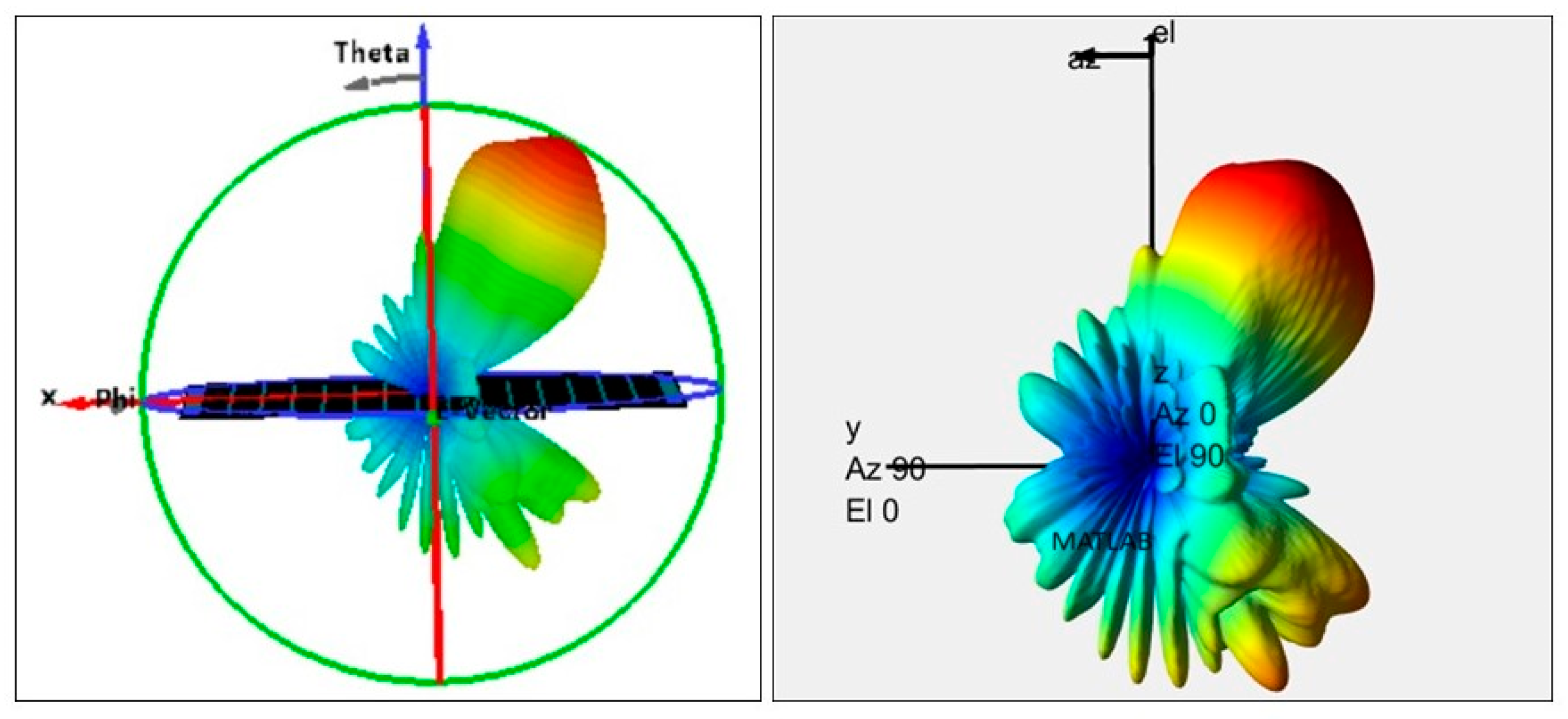
After the design and fabrication of the prototype of the proposed reflectarray, both the reflection and radiation characteristics of the design is then exported from CST to MATLAB to create a replica as a custom antenna. The Phi/Theta to Azimuth/Elevation conversion has been performed to align with the coordinate systems in MATLAB and CST Microwave Studio. The important satellite metrics can be summarised in relation to payload performance, space requirements, and data accuracy. Key metrics include gain, beamwidth, and size of the antenna mounted on the satellite. A chart summarising these key metrics is added in
Table 4.
As shown in
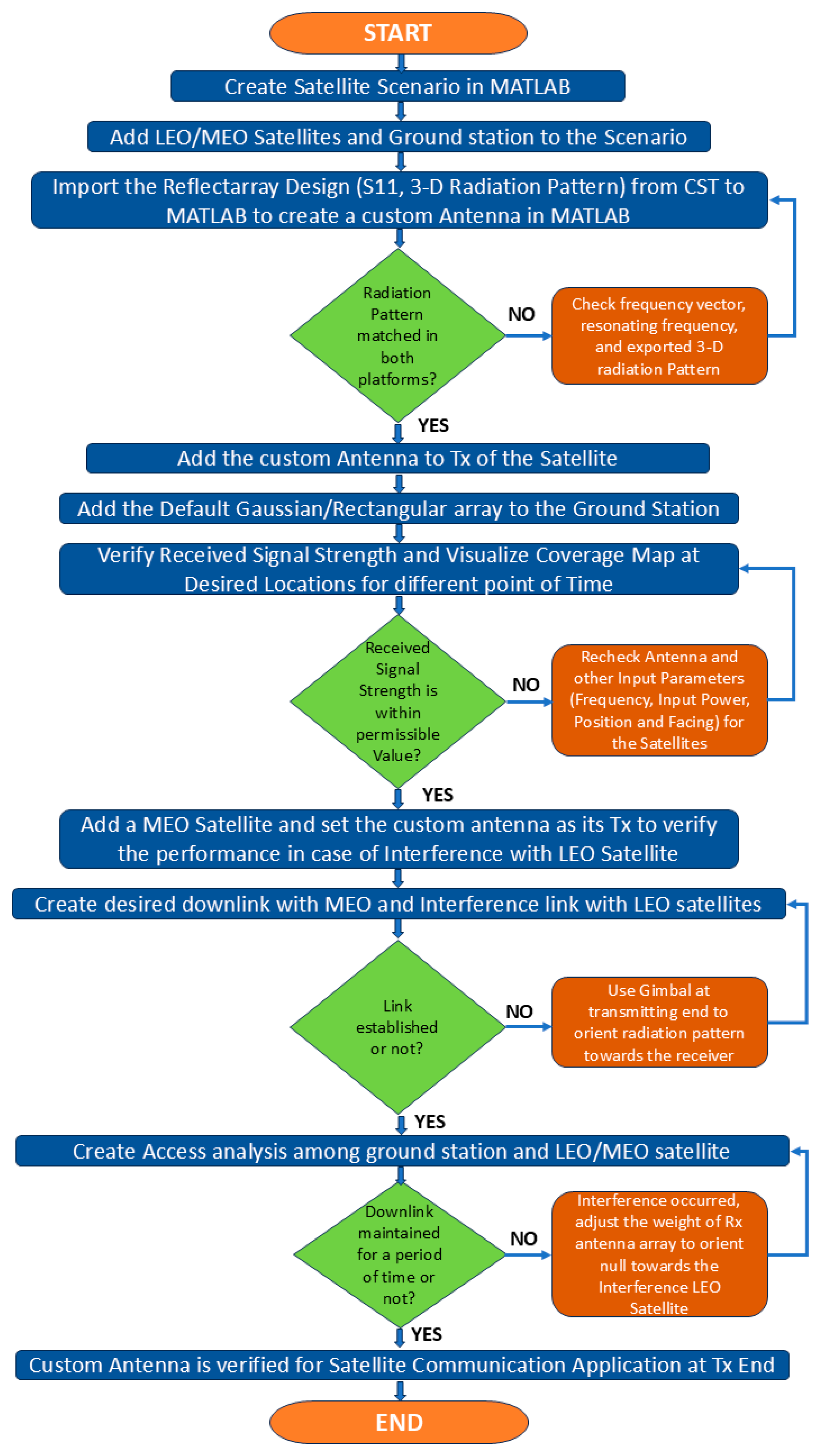
Figure 9, after matching the 3D radiation pattern of the reflectarray on both platforms, the antenna is then evaluated for its performance in a real-time simulation environment. Initially, a satellite communication scenario is created in MATLAB with Low Earth Orbit (LEO) satellites and ground stations. Then, the designed custom antenna is mounted as the transmitter at LEO Satellites to evaluate receiver signal strengths at the desired ground station locations for a specified period. After that, the same custom antenna is used as a transmitter in a MEO satellite to evaluate the usefulness of the designed reflectarray in the case of interference with LEO satellites. The detailed flow of the real-time simulation environment testing process for the proposed reflectarray is presented in
Figure 10.
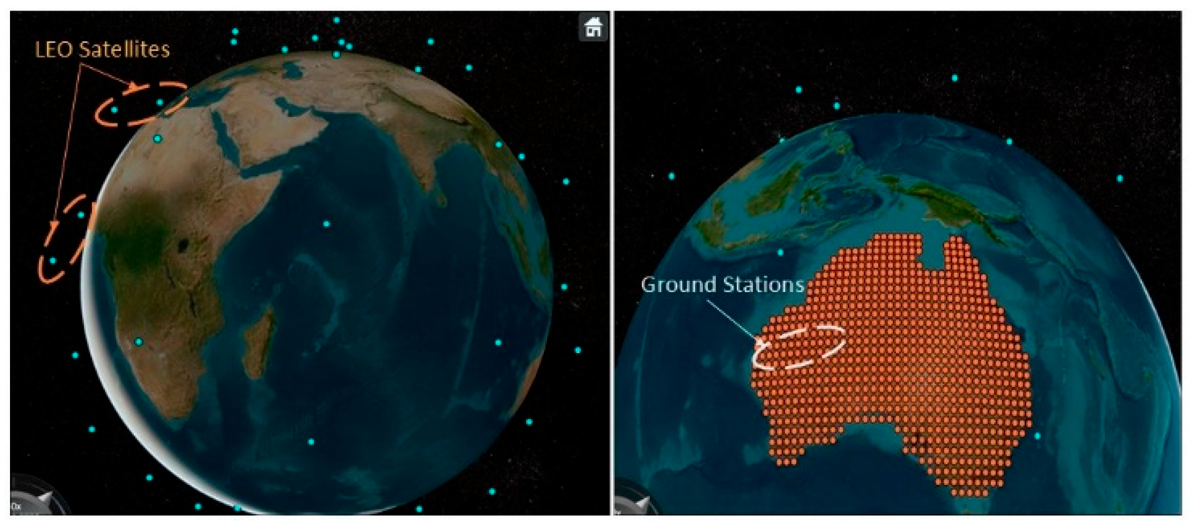
Initially, with the help of the Satellite Communication Toolbox in MATLAB, a satellite environment is created with a specified date and time. After that, satellites and ground stations are added as per their orbits around the Earth. In our case, the scenario is replicated from the Iridium NEXT satellite network, which contains 66 LEO satellites. The satellites are placed in six orbital planes with a difference of approximately 30-degree angles. In the next step, a ground station grid is created with specified latitude/longitude values from Google Earth to generate a coverage map and evaluate the received signal strength at the desired locations. The entire scenario, along with the Earth’s orbit, is designed to operate at a 12 GHz frequency, as depicted in
Figure 11.
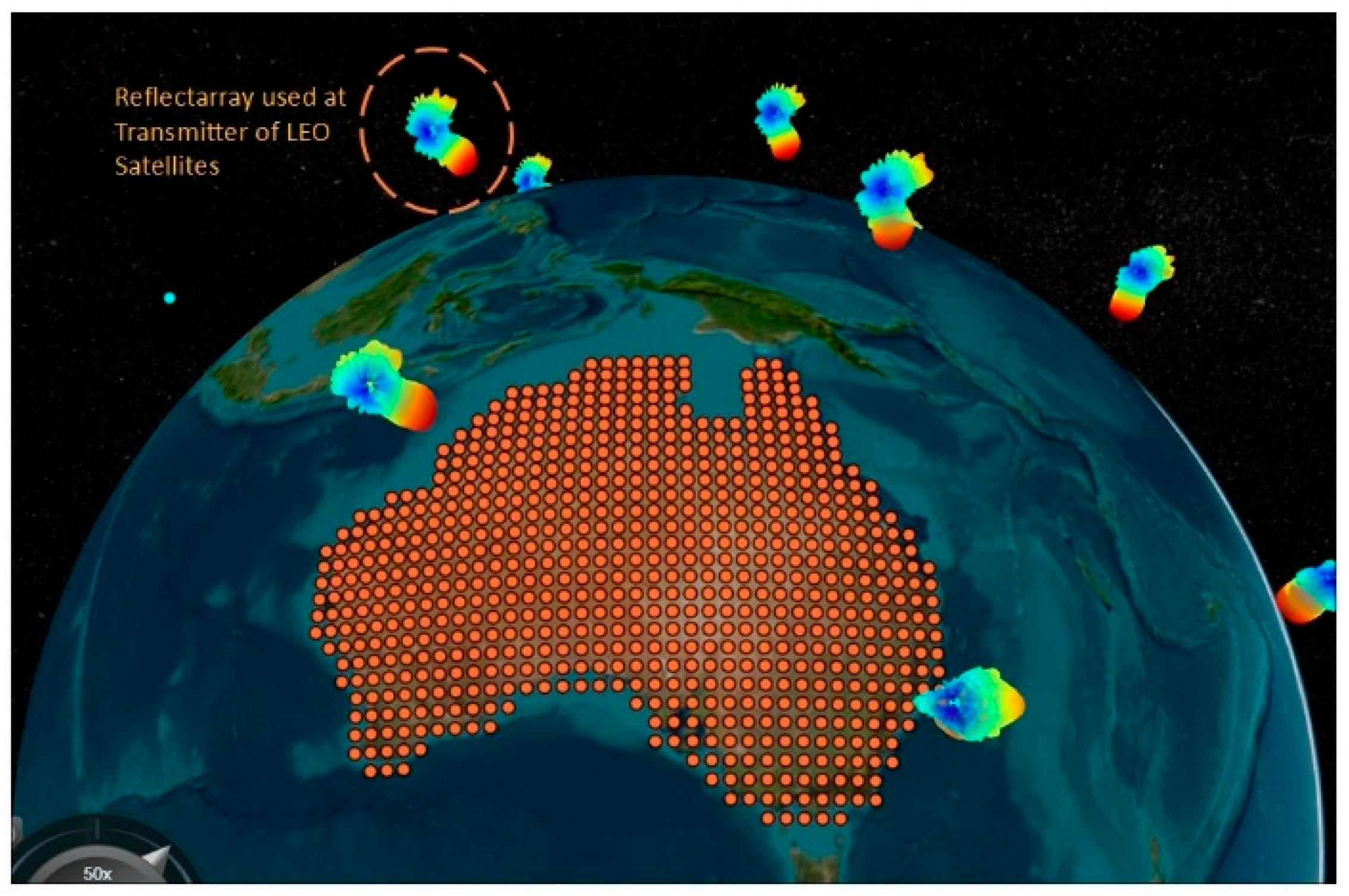
To incorporate the custom reflectarray antenna into this satellite scenario, it is assigned as the transmitter for the Low Earth Orbit (LEO) satellites. For the ground stations, the MATLAB inbuilt Gaussian antenna is taken into consideration. The 3D radiation pattern from the LEO satellite can be visualised in
Figure 12, which clearly shows the radiation pattern of the proposed reflectarray design with a 30-degree phase shift from the main beam.
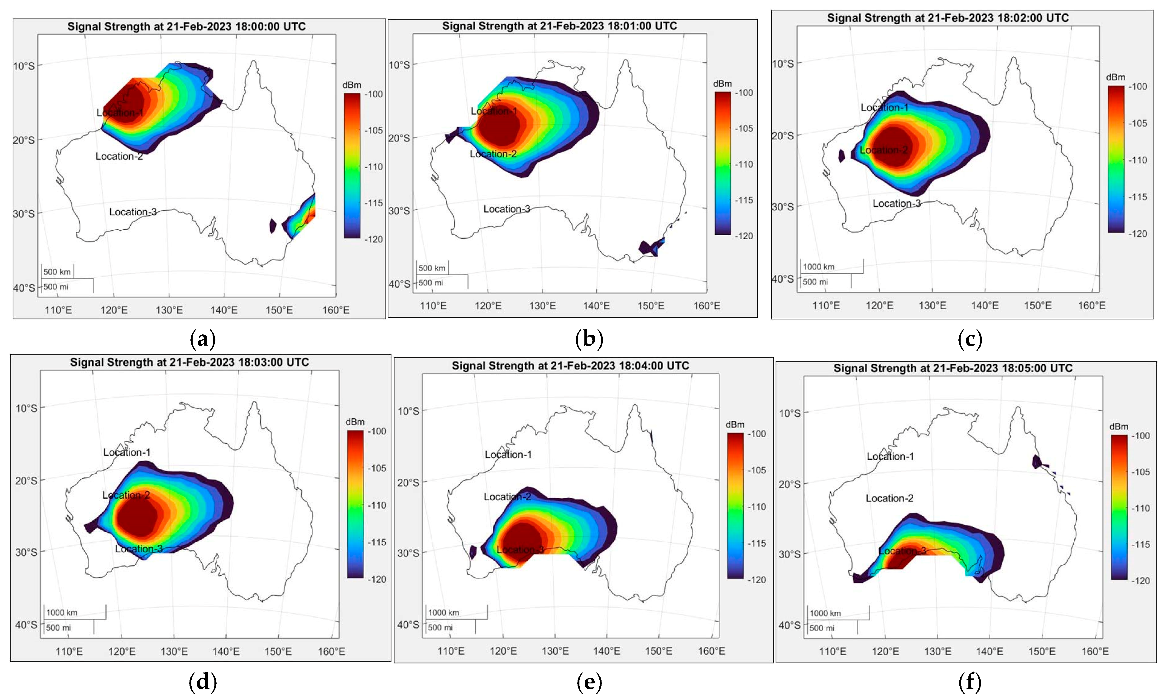
Then, to project the coverage on the map of the selected location, the raster coverage map data is displayed as a 2D contour display. The coverage map displays the intensity of the signal level received at each ground station at that location. Combined, it will provide a coverage map of the entire area based on the grid. The coverage map is then evaluated for six different times with a gap of 1 min for the same location, as shown in
Figure 13. From the figure, it can be observed that the signal strength at the ground station varies over time as the LEO satellite rotates. To further evaluate the performance of the transmitter reflectarray, the receiver signal strength value is measured at three different locations with a transmit power of 11 dB, as shown in
Table 5. The locations of these three different locations are decided based on the latitude/longitude from Google Earth. From
Table 5, it can be observed that the received signal strength varies at different locations over time, depending on the satellite’s location. At Time-1, coverage is only available at Location-1, but not at Locations 2 and 3. Similarly, Locations 2 and 3 are covered by the LEO satellite at times 2 and 4. In all cases, the receivers at three different locations have a good signal strength, ranging from −100 dB to −116 dB. This demonstrates the effectiveness of the designed reflectarray as a satellite transmitter antenna.
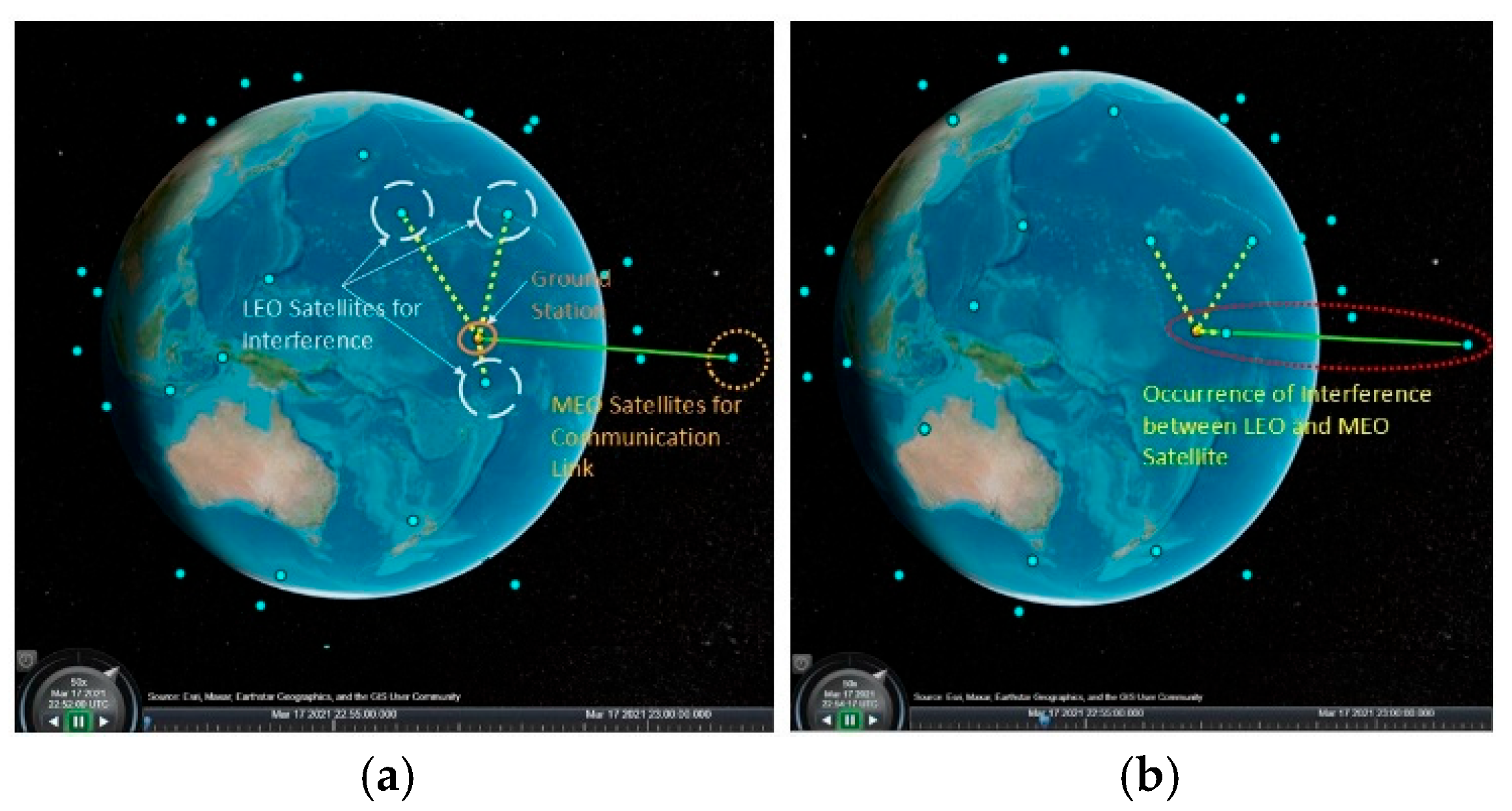
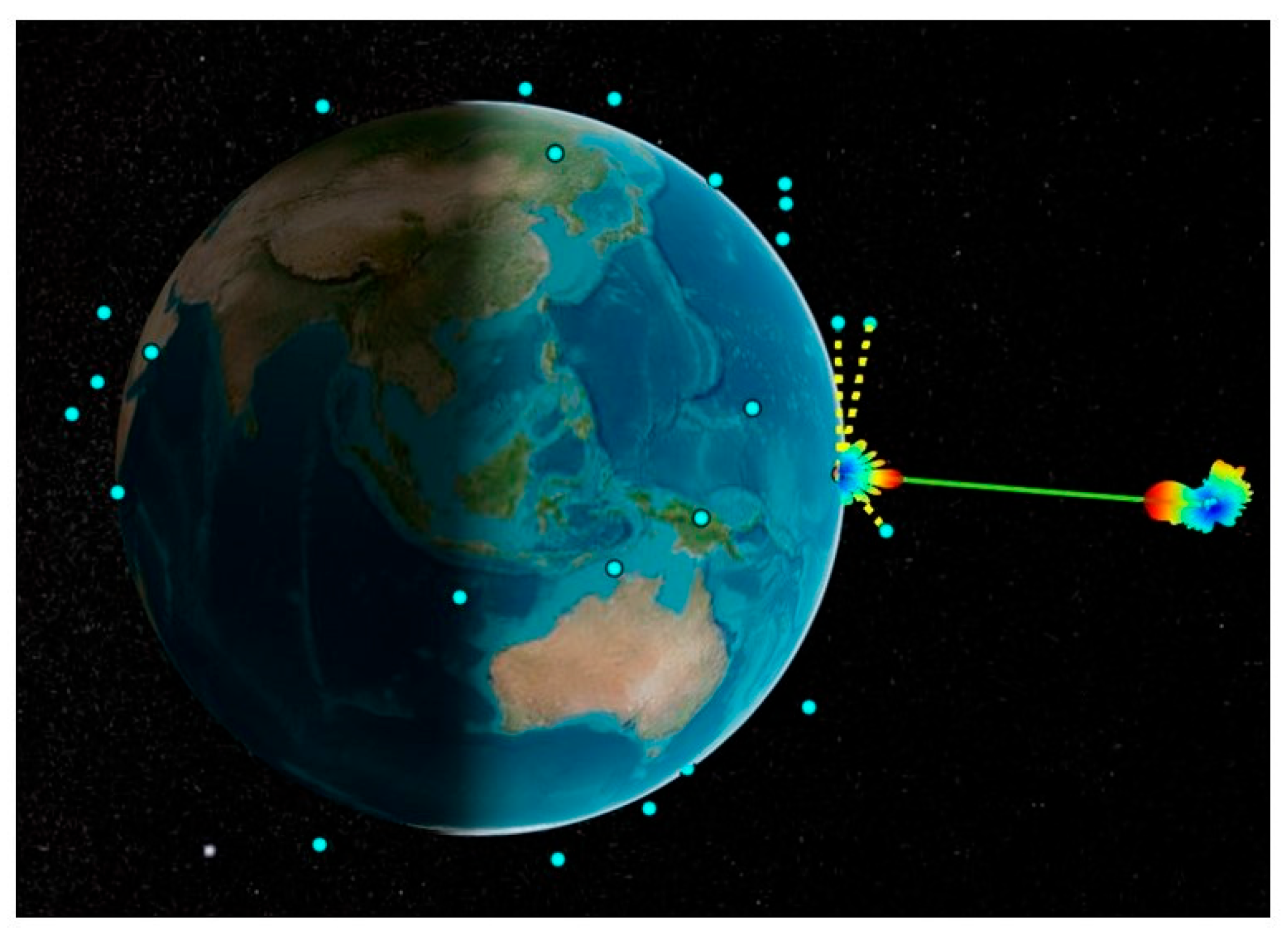
After the successful coverage evaluation at the ground stations, the performance of the reflectarray is now evaluated on the interference of a downlink from a Medium Earth (MEO) satellite to the ground station. The purpose of this test is to continue downlink to the ground station from MEO satellite without the interference of LEO satellites. The scenario involving LEO/MEO satellites and a ground station is shown in
Figure 14a. In a practical scenario, sometimes LEO satellites and MEO satellites’ paths interfere with each other while rotating around the earth, as shown in
Figure 14b.
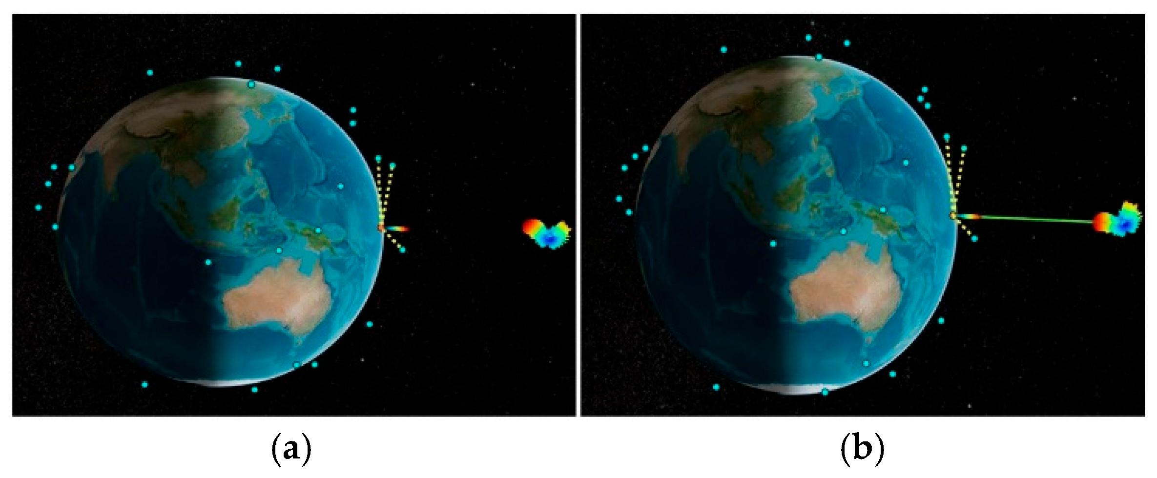
After creating the satellite scenario, the custom antenna equivalent of the proposed reflectarray design is mounted onto the transmitter of the MEO satellite. The same Gaussian antenna is used at the receiver of the ground station. The MEO satellite is designed to operate at 12 GHz, and all the LEO satellites are set to operate at 11.99 GHz to create an interference scenario with the MEO satellite. As the designed reflectarray has a phase shift of 30 degrees from its main beam, the radiation pattern is not pointed towards the ground station receiver. The downlink between the MEO satellite and the ground station is not possible, as seen in
Figure 15a. Hence, to reorient the transmitter antenna pattern exactly towards the receiver side, the gimbal is used at the MEO satellite. Gimbal is used in satellites for the precise aiming of communication equipment towards the earth’s ground station. It plays an important role in stabilising the satellite to track the target receiver as well as to point the solar panel towards the sun while rotating around the earth. Now, the main beam is reoriented towards the receiver. Hence, in
Figure 15b, the downlink is now possible after using the gimbal.
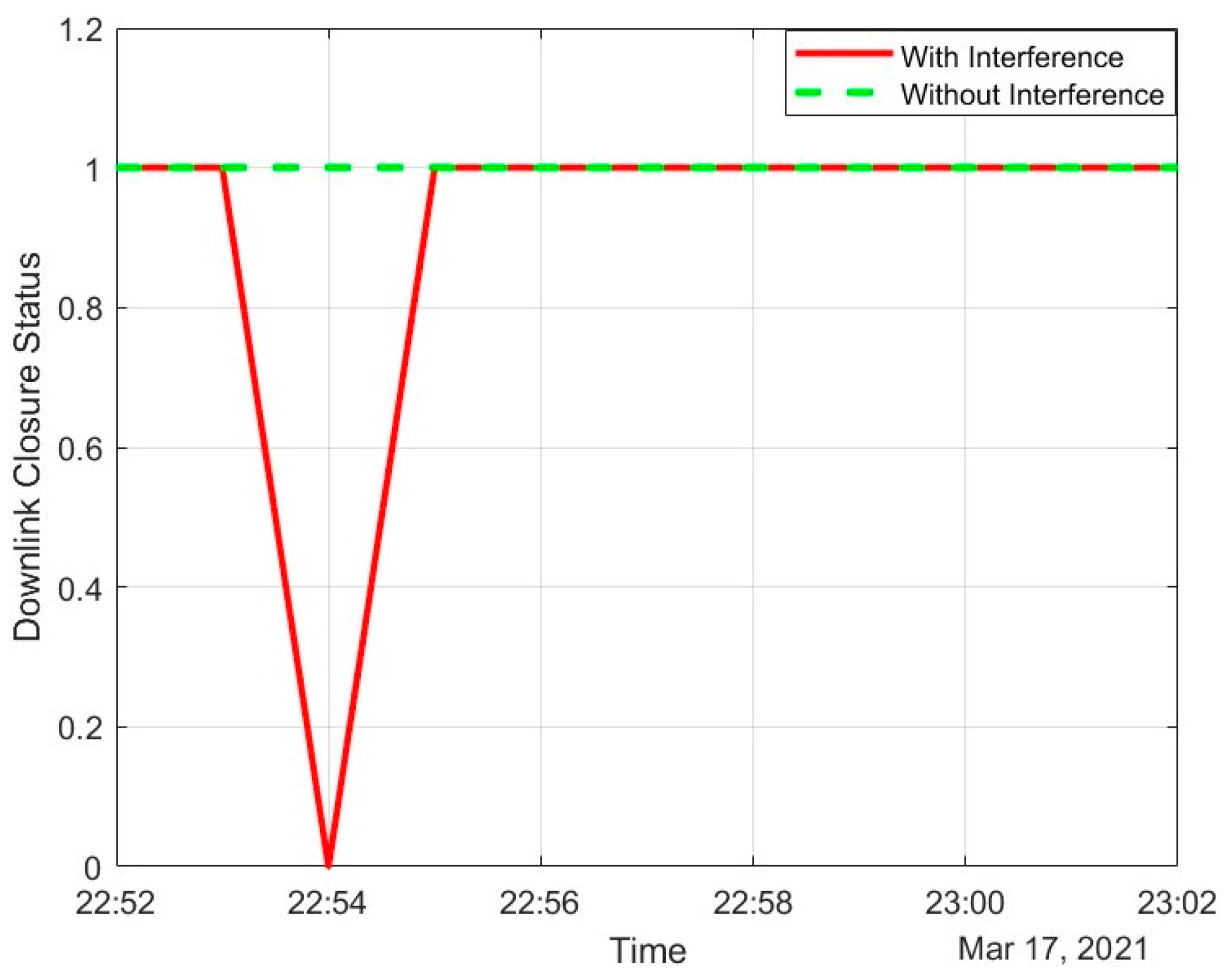
The scenario is created at 22:52 UTC, where three LEO satellites are close to the path between an MEO satellite and the ground station. However, exactly 2 min later, at 22:54 UTC, a LEO satellite moved into the path, creating interference. During that period, a sudden drop in the downlink is visible in
Figure 16.
Figure 16 depicts the downlink closure status from the desired MEO satellite over a period both with and without interference from LEO satellites. Whenever the downlink is closed successfully, the status is set to true; for any failure in the downlink, it is set to false. The status is indicated in terms of 1 and 0 for true and false cases, respectively. Our sole purpose is to avoid this interference at all times to maintain the downlink. This interference can be avoided either from the transmitter satellite end or from the receiver ground station end. However, due to space and modification constraints at the satellite end, it is challenging to modify any parameter once the satellite has been launched. Hence, the scope is limited to modifications at the ground station without altering anything at the satellite.
Hence, to avoid interferences, the Gaussian antenna is replaced by a rectangular array at the ground station receiver and its radiation pattern is shown in
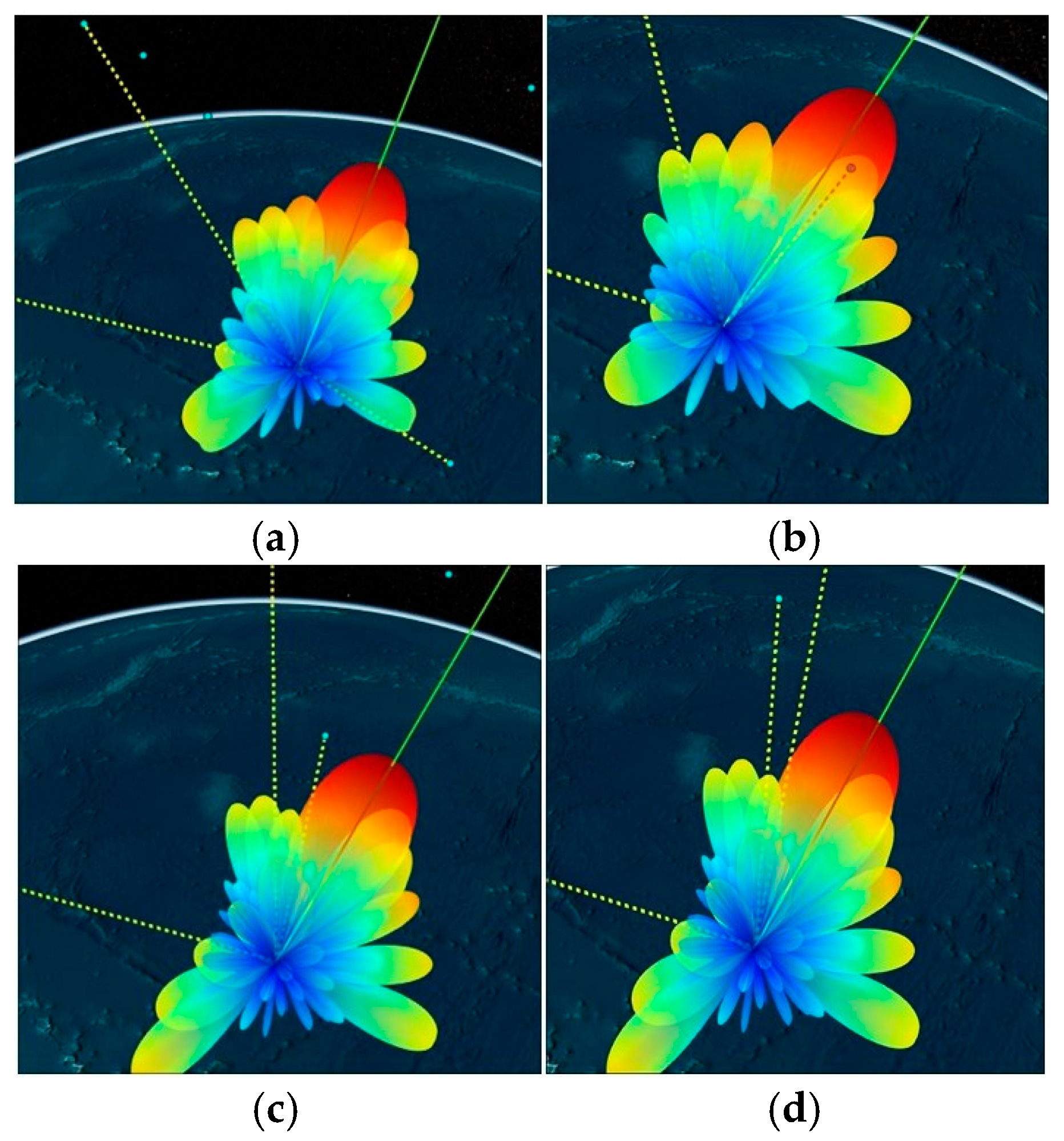
Figure 17. An 8 × 8 uniform rectangular array is designed at the same 12 GHz frequency, with both row and column element spacings equal to half of its operating wavelength. It creates a more pointed beam in a particular direction. It can orient its main beam towards desired directions while placing null or side lobes with a low gain pattern towards interference directions.
The manoeuvring of pattern can be carried out by carefully adjusting the amplitude and phase weight of excitation for each element in the array. The same concept is used here to orient the main beam towards the desired MEO satellites while placing nulls or side lobes towards the interference from LEO satellites. The ground station continuously tracks the position of its nearby LEO/MEO satellites. It adjusts its weights accordingly when the LEO satellite path comes close to the MEO satellite.
Figure 18 shows the radiation patterns of the rectangular array at the receiver with respect to different positions of LEO satellites at different points in time. The array automatically adjusts its weights to produce different radiation patterns at various times. In all the cases, the main beam is oriented towards the MEO satellite and nulls are oriented towards the LEO satellite to avoid interference.
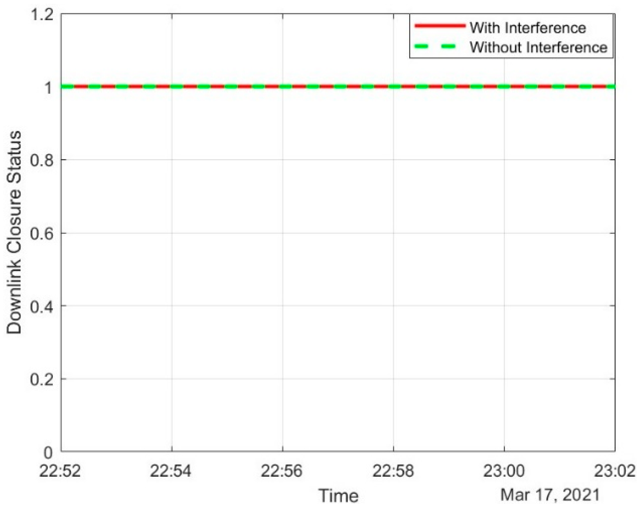
Now, the same downlink closure status is re-evaluated after replacing the array with a Gaussian antenna in
Figure 19. Previously, the downlink could not be closed at 22:54 UTC due to excessive interference from the LEO satellites. However, the downlink link status is now always up, even in the presence of interferences. The plots in
Figure 19 can visually confirm this.
The performance of the proposed reflectarray is now evaluated in a MATLAB real-time simulation environment by creating a custom antenna replica from measured reflection and radiation characteristics. The reflectarray demonstrates its effectiveness in sharing a substantial amount of signal strength with ground stations from LEO satellites. Similarly, it exhibits stable performance characteristics in scenarios where both LEO and MEO satellites transmit simultaneously without any impact on the orbit. This real-time simulation environment evaluates the usefulness of reflectarrays in satellite communication by successfully estimating theoretical concepts.


 ,
, 

