Article

Optimized Non-Integer with Disturbance Observer Frequency Control for Resilient Modern Airport Microgrid Systems

by
Amr A. Raslan
1,
Mokhtar Aly
2,
Emad A. Mohamed
1,3,
Waleed Alhosaini
4,*,
Emad M. Ahmed
4,
Loai S. Nasrat
1 and
Sayed M. Said
1
1
Department of Electrical Engineering, Faculty of Engineering, Aswan University, Aswan 81542, Egypt
2
Facultad de Ingeniería, Arquitectura y Diseño, Universidad San Sebastián, Bellavista 7, Santiago 8420524, Chile
3
Department of Electrical Engineering, College of Engineering, Prince Sattam bin Abdulaziz University, Al Kharj 16278, Saudi Arabia
4
Department of Electrical Engineering, College of Engineering, Jouf University, Sakaka 72388, Saudi Arabia
*
Author to whom correspondence should be addressed.
Fractal Fract. 2025, 9(6), 354; https://doi.org/10.3390/fractalfract9060354
Submission received: 15 April 2025 / Revised: 20 May 2025 / Accepted: 26 May 2025 / Published: 28 May 2025
(This article belongs to the Special Issue Fractional-Order Dynamics and Control in Green Energy Systems)

Abstract

Various sectors focus on transitioning to clean and renewable energy sources, particularly airport microgrids (AMGs), which offer the potential for highly reliable and resilient operations. As airports increasingly integrate renewable energy sources, ensuring stable and efficient power becomes a critical challenge. In this context, maintaining proper frequency is essential for the reliable operation of AMGs, which helps maintain grid stability and reliable operation. This paper proposes a new hybrid disturbance observer-based controller with a fractional-order controller (DOBC/FOC) for operating AMGs with high levels of renewable energy integration and advanced frequency regulation (FR) capabilities. The proposed controller utilizes DOBC coupled with a non-integer FOC for load frequency control (LFC), optimized for peak performance under varying operational conditions. In addition, a decentralized control strategy is introduced to manage the participation of electric vehicles and lithium-ion battery systems within the airport’s energy ecosystem, enabling effective demand response and energy storage utilization. Furthermore, the parameters of these controllers are optimized simultaneously to ensure optimal performance in both transient and steady-state conditions. The proposed DOBC/FOC controller demonstrates strong performance and reliability according to simulation outcomes, showcasing its superior performance in maintaining frequency stability, reducing fluctuations, and ensuring continuous power supply in diverse operating scenarios, such as 55.5% and 76.5% in step load perturbations when compared to the utilization of electric vehicles (EVs) and electric aircraft (EAC), respectively. These results underline the potential of this approach in enhancing the resilience and sustainability of AMG and contributing to more intelligent and eco-friendly airport infrastructure.

1. Introduction

1.1. Overview

Increasing pollution in the world is the price of urbanization. The massive population growth and the trend toward industrialization lead to a reduction in agricultural land and climate change. Every year, the number of city dwellers increases, and the use of transportation increases, contributing to higher carbon dioxide emissions. The world is moving toward a low-carbon economy, and communities need to address these challenges, which have become among the most critical issues for cities [1]. Transportation accounts for nearly a quarter of atmospheric carbon emissions, primarily resulting from fuel combustion activities. Aviation alone accounts for 3% of this total, which is expected to increase as the aviation sector grows at an annual rate of 6% [2].
Global plans have been developed to reduce environmental carbon emissions. Governments and relevant organizations have begun to adopt practical measures to address the ecological challenges of the aviation industry, focusing on decarbonizing aviation emissions using EAC [3]. EAC represents a significant advance in aviation technology thanks to its many benefits. Its main advantage is the lower carbon emissions, which contribute to a greener environment and slow the pace of climate change. These aircraft are considered a sustainable alternative to traditional fuel-powered aircraft. In addition, flying in an electric aircraft is much quieter, which significantly reduces noise pollution in the air and at airports. This quieter operation can improve the quality of life for residents living near airports [4].
Traditional solutions, such as increasing the capacity of the main electrical grid, can be considered to meet energy needs and achieve equilibrium between supply and demand in airport energy systems. However, these solutions require significant investments and face challenges related to the limited availability of land and resources. Furthermore, expanding energy generation, transmission, and distribution networks can lead to higher electricity costs for airports, increased transmission losses, and increased environmental pollution [5].
To address these challenges, using renewable energy sources (RESs) and local microgrids in airports has been proposed as a solution that can provide clean and affordable electricity. This strategy not only helps in reducing the financial costs associated with electricity but also contributes to minimizing negative environmental impacts and promoting environmental sustainability. It is worth mentioning that local microgrids offer additional advantages, such as improving network resilience and increasing energy use efficiency [6]. These microgrids can function autonomously or alongside the main grid, enhancing the airport’s ability to handle emergencies and provide continuous power at all times. Using RESs, such as wind turbines and solar energy, can be beneficial in providing clean energy and reducing pollution for independent airport systems. However, alongside their benefits, these sources also face challenges and difficulties [7].
The further development of electric aircraft systems requires providing RESs and an independent AMG system, in addition to the ability to coordinate with other sources such as diesel generators, energy storage systems (ESSs), EVs, EACs, etc. [8]. AMGs relying on RESs, like solar and wind, face several prominent challenges. These include variable energy production and low inertia, which lead to an imbalance between supply and demand, with frequency deviations affecting system stability [9,10]. To address these challenges, strategies such as LFC are implemented to ensure frequency stability, guarantee resiliency, and improve energy quality in AMGs [11].

1.2. Literature Review

The loads in the power system are inherently unpredictable and uncertain, indirectly affecting the system’s frequency. This leads to unfavorable conditions due to the inherent variability of RESs. Consequently, this issue can be managed within the desired limits through the LFC mechanism by regulating generation power, energy storage devices, and/or flexible loads to minimize frequency deviation. This FR technique is achieved through the use of LFC. Frequency control has become a high priority for researchers who aim to enhance system stability and reliability, necessitating continuous advancements to ensure robust control and prevent blackouts. Various aspects and types of LFC have been engineered and validated in real-world power systems to monitor and stabilize these fluctuations. The LFC methods found in the literature can primarily be categorized based on different power system structures, the number of control loops, and the type of controller used in various configurations, such as single-area and multi-area interconnected power systems [12,13]. Furthermore, LFC methods are classified according to the number of integrated control loops, establishing different degrees of freedom (DOF) [14].
Various control techniques have been employed to mitigate system frequency fluctuations, each offering unique advantages for different system requirements. Among these, intelligent control techniques have gained popularity, including fuzzy logic controllers [15], artificial neural networks [16], and adaptive neuro-fuzzy controllers [17]. Additionally, robust control techniques, such as the H-infinity technique, sliding mode control, and μ -synthesis [18,19], have been widely applied to ensure stability in uncertain environments. Optimal control methods like the linear quadratic Gaussian (LQG) [20] and linear quadratic regulator (LQR) [21] are also utilized to achieve optimal performance under specific system constraints. Furthermore, hybrid control techniques that combine sliding mode controllers (SMC) with type-2 fuzzy logic [22,23] offer increased robustness. Integer-order (IO) controllers, often integrated with other methods, remain essential to control systems. In contrast, the proportional-integral-derivative (PID) controller continues to dominate industrial control loops due to its simple design, cost-effectiveness, reliable performance, and user-friendliness [24]. Lastly, fractional-order controller (FOC) methods, with various structures and combinations [25], are emerging as a promising approach, which will be the focus of this article.
Researchers have been focused on developing optimal PID controllers using various optimization techniques to overcome challenges and enhance system reliability. Among the approaches employed to fine-tune PID parameters are the grasshopper optimization algorithm [26], ant colony optimization technique [27], Jaya algorithm [28], and class topper optimization algorithm [29]. Although PID controllers are widely used in numerous industrial applications, they face difficulties with system nonlinearities, uncertainties in modeled plants, and the precision of their parameters. In contrast, FOCs have emerged as a promising solution for power system stabilization due to their flexible configuration and higher degree of freedom. A notable member of the FOC family is the Tilt Integral Derivative (TID) controller, which has been recently applied to address the LFC problem due to its ability to fine-tune closed-loop system parameters, superior disturbance rejection, and improved reliability and robustness [30,31]. Another member of the FOC family is the fractional-order proportional-integral-derivative (FOPID) controller [32].
The FOPID controller has been successfully applied in various electrical power systems [33,34]. Hybrid controllers that combine the features of FOPID and TID controllers offer researchers a wide range of opportunities for innovation and diversity in controller design, helping to address various challenges [35]. Additionally, there has been increasing interest in cascaded controllers (CCs), which provide additional tuning possibilities and lead to enhanced performance compared to traditional single controllers. As a result, numerous studies have explored different CC configurations to tackle the LFC problem [36]. Another approach involves designing controllers that combine two different types to leverage the advantages of both algorithms. The combination of model predictive control (MPC) and LQG controllers has been validated in [37]. An adaptive MPC combined with a recursive polynomial model estimator has also been suggested in [38]. Furthermore, the use of the integral-proportional-derivative (I-PD) controller and the integral-tilt-derivative (I-TD) controller has been explored in [39,40].
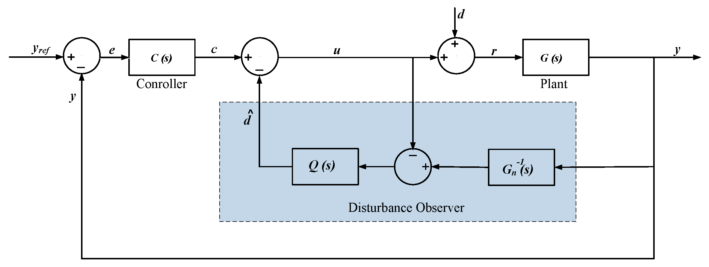
Building on the existing literature on LFC, several studies have introduced an auxiliary controller that estimates disturbances within the system, regardless of the primary controller in use. This supplementary controller can be integrated into any pre-existing control framework to boost its operational efficiency, and it is referred to as disturbance-observer-based control (DOBC) [41,42]. Numerous studies have demonstrated the application of DOBC for control in various fields, where it effectively mitigates the impact of external disturbances and ensures the desired control outcomes [43,44,45]. To further optimize controller performance and reduce frequency deviations, this work proposes an enhanced DOBC implementation for frequency control in microgrids experiencing reduced system inertia due to high renewable penetration.
Little attention has been given to evaluating robust controllers tailored to AMGs. Key challenges for AMGs include managing fluctuating electrical loads due to aircraft movements and maintaining grid frequency stability amidst rising energy demands. The main advantages of AMGs include improved power quality, a reliable power source, increased flexibility, reduced feeder capacity, reduced transmission losses, increased penetration of RESs, and reduced pollution [46]. The most challenging factors in the islanded AMG system are the RES-generated power uncertainty, low inertia, dynamic nature, and nonlinear structure. Each of these factors can create an imbalance of supply and demand in the power generation and consumption dynamics of the AMG system, leading to deviations in the frequency from their nominal values and instability and inversely affecting power quality and reliability. To address such challenges in the isolated AMG, the LFC strategy and controlling flexible loads mechanism can be employed [8,9,10].

1.3. Paper Contribution

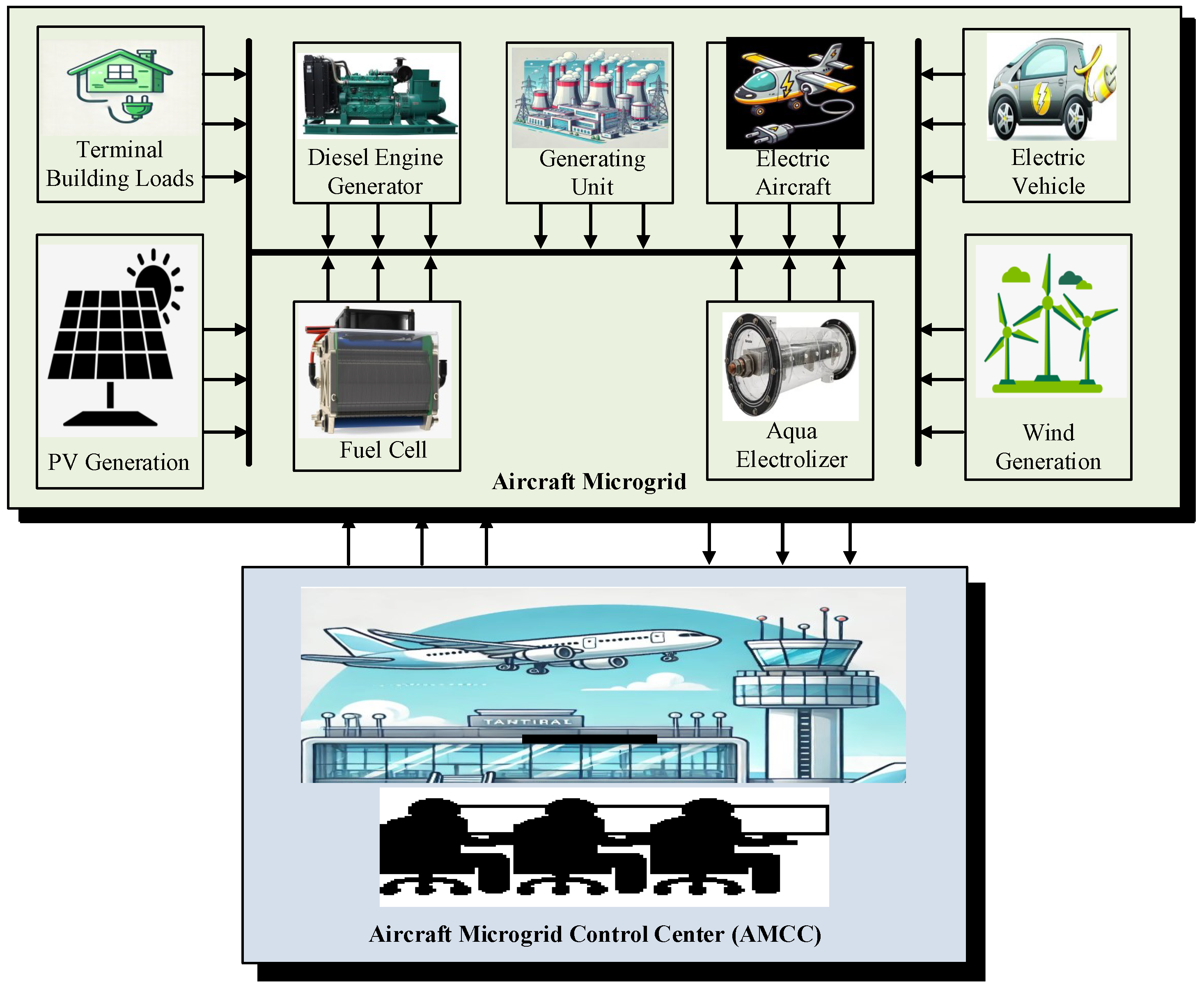
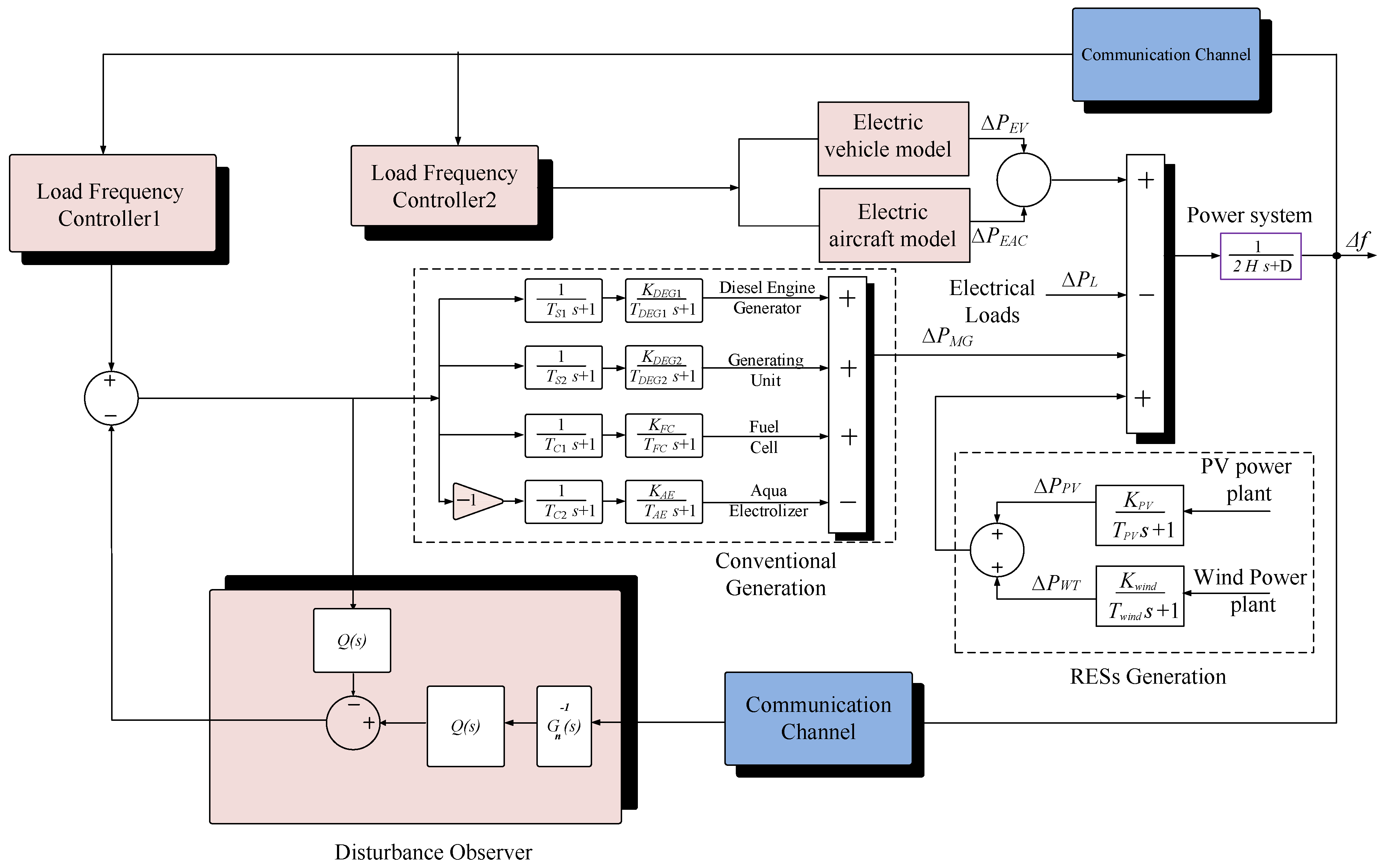
The LFC method is crucial in isolated AMGs, as it helps limit frequency deviations within predefined constraints by minimizing the gap between generated power and load demand [11]. To address this issue, this study introduces an isolated airport microgrid consisting of solar photovoltaic (PV), diesel engine generator (DEG), fuel cell (FC), and aqua electrolyzer (AE). The system also includes energy storage devices such as batteries and EAC, adding complexity to the control of the microgrid system. Therefore, precise coordination within the grid infrastructure is essential for meeting the unique energy storage and supply needs and for dependable frequency regulation in the islanded AMG system [
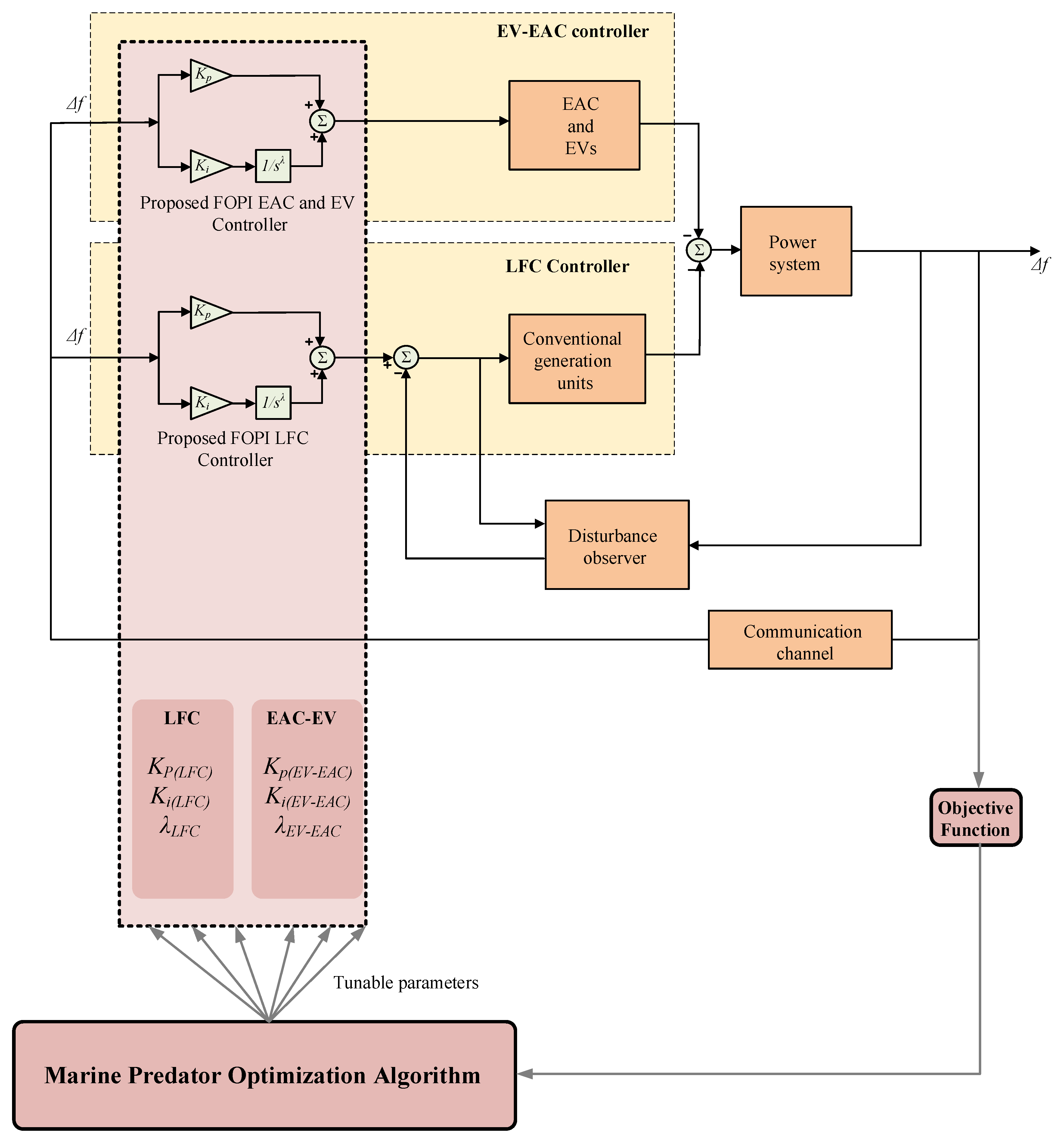
47]. This research advances a DOBC methodology to optimize the hybrid renewable-storage system’s dynamic performance.
The primary contributions of this study are summarized as follows:
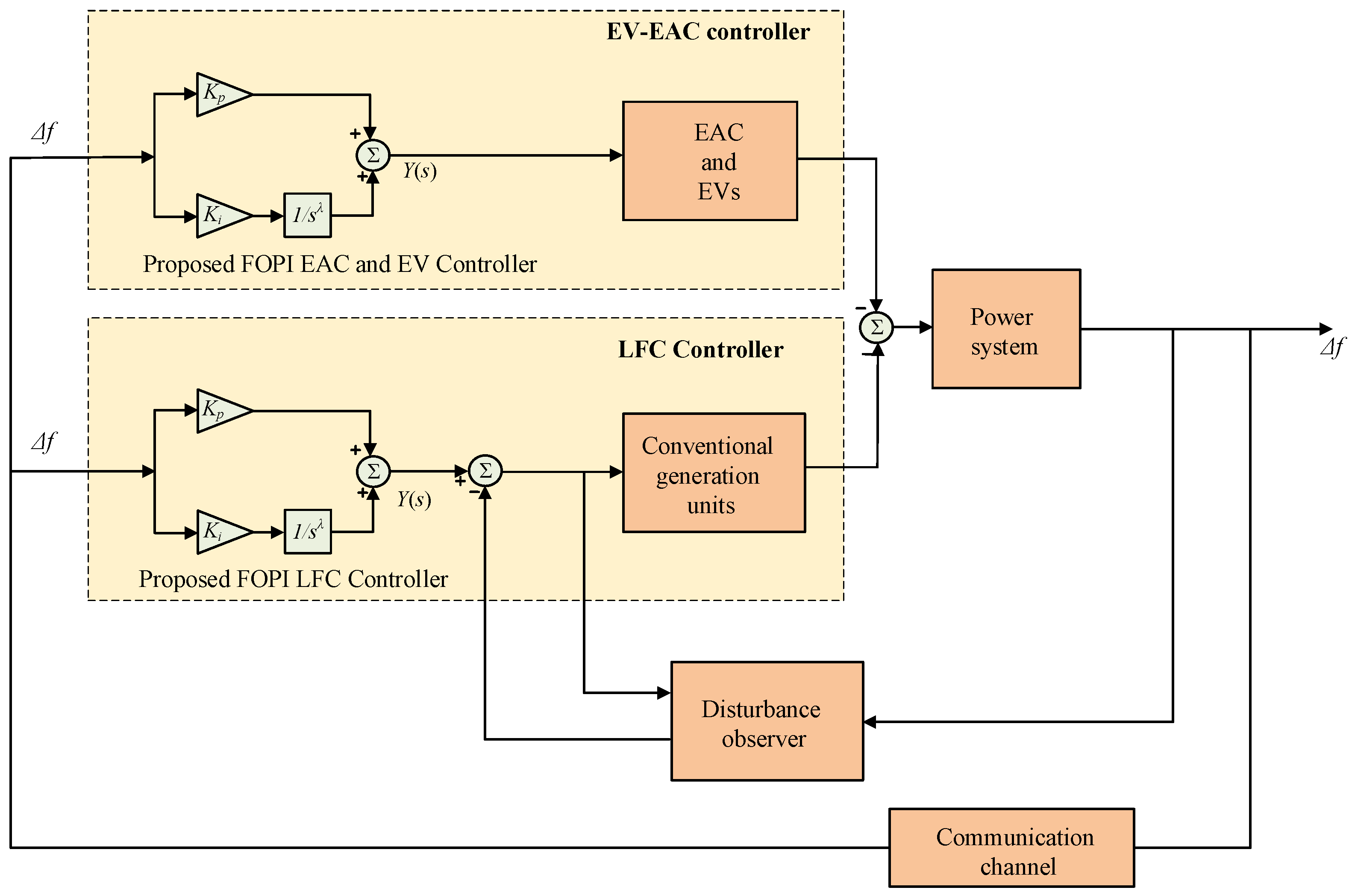
  • A hybrid controller using DOBC and FOC for frequency regulation in AMG systems is developed. The proposed DOBC injects a compensation signal into the control system, which represents the total disturbances from loads and renewables. Furthermore, the joint optimized FOC methods in LFC and in controlling EAC and EVs provide enhanced performance of the frequency regulation controller.
  • A resilient operation of the AMG system is proposed by regulating frequency and utilizing lithium-ion batteries from modern EAC and EV systems. The proposed optimized FOC enhances the contribution of available batteries in EACs and EVs to participate in frequency regulation.
  • Optimized design with robust disturbance rejection and fast response in AMG is proposed in this paper, which considers various severe operating scenarios in AMG systems. The proposed method provides an optimized FOC set of possible parameters for tuning, leading to guaranteed optimized performance.
The remainder of the paper is organized as follows: Section 2 presents the components and modeling of AMG systems. The proposed controller is derived and detailed in Section 3. The design methodology and optimization program are also provided in this section. The obtained results and discussions under different scenarios are given in Section 4. The paper is concluded in Section 5.

2. Modeling of Islanded AMG System

2.1. System Structure and Components

The developed AMG system is illustrated in Figure 1. The proposed AMG case study considers the integration of solar and PV renewable sources, the contribution of installed EAC and EVs, and the possible integration of green hydrogen systems. The considered AMG includes the following:
  • The studied AMG system integrates several distributed generation sources, including AC and DC generators, linked to the AC bus via power electronic converters (PECs).
  • The AC units include wind turbine generators (WTG), DEG, and conventional thermal generation.
  • At the same time, the DC units consist of a photovoltaic solar panel, FC, and AE. The DC components interface with the AC bus via bidirectional DC/AC power conversion systems.
  • Additionally, the power generated from EVs and EAC is linked to the AC bus via bidirectional DC/AC power inverters.
  • The AMG control center oversees the operation and management of the connected AMG components, ensuring proper coordination and control under various operational conditions.
It is worth mentioning that the analysis in the paper is based on average models of each element of the AMG, and the Laplace transform of first-order models is widely employed in this type of analysis.

2.2. Dynamic Model of Airport Microgrid

Figure 2 shows the complete dynamical model and mathematical representation. A model of the analyzed islanded AMG is designed to examine and evaluate the proposed system DOBC with the FOC-based LFC scheme. The proposed model is based on cascaded first-order transfer functions (TFs), as presented in the literature [30]. Moreover, the installed RESs are also modeled with the stochastic property of generated power from PV panels for the included wind turbine and PV generators. Also, the microgrid has a conventional DEG unit and a thermal power generation unit. The lithium-ion batteries used in the installed EAC and EVs are designed to participate actively in FR functionality. The proposed case study uses FC and AE units to consider future green hydrogen. Installed FCs can provide clean, sustainable power owing to their superior efficiency and minimal emissions. Simultaneously, the AE offers a robust hydrogen storage and generation solution, enhancing renewable energy integration and reducing reliance on fossil fuels [48].

2.3. EAC Model

Several dynamic models have been introduced to simulate the behavior of EAC and its associated storage devices. Most focus on aerodynamic converter modeling or flight modeling [49,50,51]. Here, the focus is on the frequency response generated by the aircraft’s combined charging/discharging cycle [52]. “Aircraft-to-Grid” (A2G) idea uses aircraft batteries as a large-scale equivalent BESS, reducing the need for extensive storage capacity installations. In addition, EAC and BESS can provide sufficient energy for upcoming trips, ensuring customer satisfaction. Monitoring aircraft batteries’ state of charge (SOC) is essential for ensuring that the charge remains above 80% before flights [53]. The proposed FOC is responsible for sending the appropriate control signal to the available Li-ion batteries of EACs, providing control of their charging/discharging power. This, in turn, helps to support the frequency regulation functionality.
The EAC model has been developed for LFC analysis in AMG. By properly using available EAC batteries, these aircraft can contribute to FR based on their available SOC, with a maximum charge limit set at 90% to prevent battery degradation. In this study, the upper SOC limit is set at 90%, and the lower limit at 80% to ensure battery efficiency and customer convenience. When the EAC reaches SOC thresholds, it does not participate in FR to avoid excessive battery depletion and to preserve its SOC for flights [54].
Figure 3 shows the complete EAC dynamical model employed in the current study. The EAC can operate in three primary modes of operation: flying, charging, and controllable [53]. In the controllable mode, EAC can contribute to desired control activities during this mode of operation. The rate at which the EAC controllers enter the controllable state per second is called the “control-in rate” ( N c o n t r o l i n ). In the flight mode, the EAC enters this mode when it takes off for its journey, transitioning from the controllable state to the flight state. Each EAC is powered by a battery with a capacity ranging from 3 to 6 kWh. In the charging mode, the EAC shifts to the charging state after landing when it is plugged in to recharge its battery.
During the 1 h charging period, the EAC is not controllable and cannot respond to LFC signals. The EACs are charged up to 80% SOC, allowing them to have sufficient charge for entering the controllable mode and responding to LFC signals. The central load dispatch center coordinates with local control centers, which oversee groups of EACs and transmit LFC signals every second. The EAC updates its SOC to the local control center every 30 s. Given the model developed in Figure 3, the proposed controller output for the EAC is denoted as Δ U E A C , while Δ P E A C represents the power output during the charging and discharging processes of EAC.
Two key operating constraints must be considered in the EAC model: Firstly, the inverter capacity constraint has to be considered, which ensures that the charging and discharging rates stay within the specified limits. The terms K 1 and K 2 represent the differences between the maximum and minimum allowable energy levels of the EAC battery and its current energy, calculated as K 1 = E c o n t r o l E m a x , and K 2 = E c o n t r o l E m i n respectively. Additionally, Δ P E A C signifies the charging/discharging power. When Δ P E A C = 0, the EAC is idle; when Δ P E A C > 0, the EAC is discharging, and when Δ P E A C < 0, the EAC is in a charging state. Secondly, the capacity of the system has to be considered, specifically the total controllable energy of all EACs, which defines the overall output capacity. After charging, EACs can only respond to LFC signals within their allowed SOC range conditions are met [55,56]
E control min E control E control max
The minimum and maximum capacities of the EAC are denoted by E c o n t r o l m i n and E c o n t r o l m a x , respectively. These values are derived from the battery capacity, C k W h , of the EAC, and correspond to the permissible SOC range of 80% to 90%, as shown in Equations (2) and (3) below:
E c o n t r o l m i n = N c o n t r o l C k W h 1000 × 80 100
E c o n t r o l m a x = N c o n t r o l C k W h 1000 × 90 100
The total number of controllable EACs, N c o n t r o l ( t ) is calculated as follows, as shown in Equation (4):
N c o n t r o l ( t ) = N i n i t i a l + N c o n t r o l i n ( t ) N p l u g o u t ( t )
where,
  • N i n i t i a l is the initial number of controllable EACs.
  • N c o n t r o l i n ( t ) represents the number of EACs that have transitioned from charging mode to controllable mode at time t.
  • N p l u g o u t ( t ) represents the number of EACs that have transitioned from the controllable state to the flight state at time t [57].

2.4. EV and V2G Model

Additional functionalities can be achieved by the installed EV batteries, leading to the elimination of the needed BESS installations in modern systems. The plans to widen the V2G and G2V concepts are encouraged. A detailed EV BESS model is developed in the current AMG study to represent the dynamics of FR using EV BESS. The EV BESS can be controlled directly by the frequency measurement signal, through LFC, or a separate controller. Figure 4 integrates different components of EV BESS, such as series R s representing thermal resistances and a branch of parallel RC R t and C t representing over voltage transients. The signals sent by the control scheme to EV BESS determine the required functionality of charging, idling, or discharging. Thanks to recent advancements in technology and reductions in prices, the lithium-ion BESS facilitated the integration and widespread adoption of EV technology. The open-circuit BESS voltage V o c as SOC-dependent variable V o c ( S O C ) is normally expressed using [58]:
V o c ( S O C ) = V n o m + S R T F l n ( S O C C n o m S O C )
where C n o m and V n o m represent nominal EV BESS capacity (Ah) and voltage, respectively. The S e n is the sensitivity indicator parameter for V o c ( S O C ) . Symbol R is used as the gas constant, F as the Faraday constant, and T as the temperature.

2.5. Renewable Energy Model

2.5.1. The PV Plant Model

Solar PV panels produce electrical energy with specific characteristics, and the maximum power point must always be tracked to obtain the most energy possible. Because of this, power electronics have become essential for connecting solar systems to the electrical grid. Devices like inverters (which convert DC to AC) and synchronization systems are widely used in solar power plants, and they come in different designs and setups. Weather conditions also significantly affect how much energy solar panels produce, often making solar power generation unpredictable. These weather changes, especially when they happen quickly, can create stability problems for solar systems. Solar PV system power generation can be characterized using the equation presented below [59]:
P P V = η Φ s o l a r S [ 1 0.005 ( T a + 25 ) ]
where,
  • η denotes the conversion efficiency of the PV panel (in percentage),
  • Φ s o l a r corresponds to the solar insolation (W/m2),
  • S presents the area of the PV unit (m2),
  • T a presents the ambient temperature in Celsius (°C).
The configuration model of a realistic PV solar generation system is implemented based on the model presented in Figure 5 [60]. White noise is used to model the variations in the generated PV power.

2.5.2. The Wind Turbine Model

The mechanical energy generation produced by a WTG system exhibits significant variability due to the fluctuating nature of wind speeds. This inconsistency in wind speed is a common characteristic of wind energy systems, and the mechanical power is determined through the following equation:
P w i n d = 1 2 ρ A r C p V w 3
In this equation, ρ represents the air density in kg/m3, A r is the swept area of the turbine blades in square meters, C p denotes the power coefficient, and V w is the wind speed in meters per second. The power coefficient C p reflects the turbine’s efficiency in converting wind power into mechanical work. A realistic wind turbine generation system model, which accounts for these factors, can be implemented as shown in Figure 6 based on the model described in [60].

2.5.3. The FC and AE Plant Model

Integrating an AE, hydrogen storage infrastructure, and FC presents a promising solution for providing long-term grid power support, especially for large-scale load demands. The AE employs water electrolysis to generate hydrogen (H2) through electrical energy. This hydrogen is subsequently compressed and stored in dedicated tanks for future utilization. When electricity demand increases, the PEMFC converts the stored hydrogen into electricity via electrochemical reactions, ensuring rapid and reliable power delivery to meet dynamic load needs.
One of the standout advantages of this approach is the efficiency it provides, which is notably higher compared to conventional single-stage energy conversion methods. By storing excess energy in the form of hydrogen, this system ensures that power is available even during periods when RESs are insufficient. The AE and FC technology combination demonstrates remarkable potential, particularly when integrated into a hybrid renewable energy system (HRES) that includes WTG and PV units. This hybrid configuration leverages the strengths of both RESs and hydrogen storage, ensuring a more resilient and flexible power supply that can meet variable energy demands effectively. This strategy enhances the energy system’s operational efficiency while fostering a more sustainable and eco-conscious energy infrastructure. The transfer functions of FC and AE are as follows [61]:
G F C ( s ) = 1 1 + s T C 1 K F C 1 + s T F C
The transfer function of the fuel cell is given by the following:
G A E ( s ) = 1 1 + s T C 2 K A E 1 + s T A E
where K AE and K FC represent the gains of AE and FC, respectively. Similarly, T AE and T FC are their associated time constants. Whereas T C 1 and T C 2 represent the power converters’ time constants of FC and AE, respectively. Summarized parameter values for the implemented AMG. The case study results are presented in Table 1.

3. Proposed Hybrid DOBC and FOC Optimized FR Controller

This work proposes a refined hybrid FR controller leveraging the synergistic combination of DOBC and the fractional-order control method. The new controller utilizes three main parts: the DOBC, the FOC LFC, and the FOC method of EAC and EVs. The position of each part in the designed control architecture is shown in Figure 2. The joint operation of the three parts has to preserve the control of frequency deviations at their minimum value, with the minimum overshoot/undershoot at sudden step load changes and the fastest response to recover the system. So, the proposed controller guarantees equilibrium between generated and consumed power by adjusting the output power of each controlled source/storage element.
In the proposed hybrid DOBC and FOC Optimized FR Controller, the DOBC detects the existing disturbances in the power system of AMG and generates a compensating signal to mitigate the disturbance effects. The injected signal d ^ represents the total existing disturbances of both generation and loading power changes as follows:
d ^ = Δ P P V + Δ P W T Δ P l
where Δ P P V , Δ P W T , and Δ P l are changes in PV power, wind outputs, and load demands in the AMG system. The following segments outline the structural elements and functionality of the developed approach, and a design scheme is provided.

3.1. Design of DOBC Method

The DOBC architecture uses an inverse plant model G n 1 ( s ) and a low-pass filter Q ( s ) to estimate and reject disturbances affecting the system. The main structure and components of DOBC are shown in Figure 7. The filter Q ( s ) ensures that high-frequency noise is filtered out while maintaining the system’s output unaffected by disturbances. In the absence of disturbances, the dynamics of the system are shown in Equation (11):
y ( s ) G n ( s ) C ( s )
If there are no uncertainties in the system parameters, the system dynamics is described using Equation (12) as follows:
y ( s ) G ( s ) C ( s )
As illustrated in Figure 2, for the application of the DOBC, assuming that information is transmitted between system components without any delay or loss and that the system parameters G ( s ) are accurately known using electric aircraft batteries G E A C ( s ) and electric vehicle batteries G E V ( s ) , the resulting transfer function for the overall system can be expressed as shown in Equation (13).
G ( s ) = G P ( s ) [ G A E ( s ) + G F C ( s ) + G D E G ( s ) + G T h ( s ) ] 1 G P ( s ) [ G E A C ( s ) + G E V ( s ) ]
The design of the filter Q ( s ) focuses on suppressing high-frequency noise. The filter transfer function is given by Equation (14). The time constant T f = 0.1 is selected to ensure a fast response without introducing a delay in critical signals. This enables the DOBC to work effectively with any secondary controller to enhance the overall system performance.
Q ( s ) = 1 ( T f s + 1 ) 2

3.2. Proposed FOC Method

The FOC provides integral, fractional, and derivative fractional operators compared with existing IOC methods. The generalized representation of the FOC operators D ν | a t is classified as [62]:
D ν | a t = ν > 0 d ν d t ν Derivative   action ν < 0 t 0 t f d t ν Integration   action ν = 0 1 Integer   control
There are numerous ways in the literature to facilitate the implementation of FOC operators. Whereas the Caputo method found wide applications. In which, the operator D ν | a t is described as [63]:
D ν | a t = 1 Γ ( n ν ) a t f ( n ) ( τ ) ( t τ ) ν n + 1 d τ
However, the majority of existing representations are not suitable for digital processing unit implementations. A more suitable solution is through the application of the Oustaloup recursive approximation (ORA) scheme for implementing FOC operators D ν | a t operators. Accordingly, this paper employs ORA to simulate and implement the FOC. In ORA method, νth derivative ( s ν ) is represented as [64,65]:
s ν ω h ν k = N N s + ω k z s + ω k p
where ω k p are ORA’s poles and ω k z are their zeros for representing ω h and they are determined using [66]:
ω k z = ω b ( ω h ω b ) k + N + 1 ν 2 2 N + 1
ω k p = ω b ( ω h ω b ) k + N + 1 + ν 2 2 N + 1
ω h ν = ( ω h ω b ) ν 2 k = N N ω k p ω k z
In ORA, the model employs a number of ( 2 N + 1 ) poles/zeros, wherein N is the desired ORA filter order. In this work, N is selected equal to 5 as a compromise between accuracy and complexity. Whereas frequency range ω is set at [ ω b ,   ω h ] at [ 10 3 ,   10 3 ] rad/s, respectively.
In this paper, the FOPI is employed in both the LFC and the control of the BESS of EAC and EV of the studied AMG system. The FOPI controllers are responsible for generating smooth control signals for the LFC and BESS in the AMG system. Compared with an IO-based conventional PI controller, the FOPI includes an additional fractional operator named λ for the integral term. The transfer function is represented as follows:
C L F C ( s ) = Y L F C ( s ) E L F C ( s ) = K p ( L F C ) + K i p ( L F C ) s λ L F C
C E V E A C ( s ) = Y E V E A C ( s ) E E V E A C ( s ) = K p ( E V E A C ) + K i ( E V E A C ) s λ E V E A C
where K p ( L F C ) and K p ( E V E A C ) are proportional gains, K i ( L F C ) and K i ( E V E A C ) are integral gains, and λ L F C and λ E V E A C are FO integral operators for both controllers, respectively. Figure 8 presents the operational structure of the fractional-order control mechanism within the novel method.

3.3. Optimizing Controller Parameters Process

Metaheuristic optimization algorithms provide several advantages in designing control systems compared with existing mathematical design approaches. They can determine the optimum set together as optimized parameters concurrently, guaranteeing optimal performance of the obtained values. The marine predator algorithm (MPA) has demonstrated powerful performance in this area in several published articles [67]. The principal inspiration for MPA is the existing Lévy-Brownian motion of the ocean’s predators. Also, optimal policy and encounter rates in biological interactions among predators and prey form the MPA algorithm. More details about the MPA principles and mathematical formulations can be found in [67,68,69], which will not be covered in this paper.
The conventional design methods for FOC determine the parameters by the parameter values of the designed controller. This, in turn, does not guarantee the optimum set together. On the other hand, the use of MPA benefits from the inherent advantages of MPA in solving engineering design problems, in addition to providing a set of optimal parameters. This, in turn, guarantees the optimized performance and design of FOC methods.
The determination methodology of optimized values of tunable control parameters is shown in Figure 9. A complete model for the studied AMG system is made in MATLAB Simulink (R2024a), including various limitations and boundaries of each modeled element. The system model is made in a flexible way to make the optimization process of controllers feasible through its integration with the MPA code. The MPA code is made in an M-file with the limiting boundaries of each tunable parameter. In each iteration, the MPA runs the simulink model with updated parameters until it reaches a global optimum set of parameters.
To reach the optimum point of parameters, an objective function is used to drive the MPA algorithm and its updated calculations. In each step, the global optimum objective function is updated and stored for the next iteration. The global objective update occurs when the newly calculated objective is lower than the previously stored optimum value. The algorithm terminates upon reaching the predefined iteration limit; the most recent set of updated parameters is outputted for use in the simulation.
A step change is made in the AMG loading in the optimization process to minimize the frequency deviation. The error-based objective functions provide a more suitable way in the literature for designing the objective function. The four main error-based objectives are represented as follows:
Integral   Square   Error   ( ISE ) = i = 1 m ( e i 2 ) d t = 0 t s ( Δ f ) 2 d t Integral   Time   Square   Error   ( ITSE ) = i = 1 m ( e i 2 ) . t d t = 0 t s ( Δ f ) 2 . t d t Integral   Absolute   Error   ( IAE ) = i = 1 m a b s ( e i ) d t = 0 t s a b s ( Δ f ) d t Integral   Time   Absolute   Error   ( ITAE ) = i = 1 m a b s ( e i ) . t d t = 0 t s a b s ( Δ f a ) . t d t
The DOBC is designed utilizing the plant model as a foundation, and the additional FOPI regulator parameters and controllers are designed using the MPA optimization after modeling the disturbance observer. The boundaries of each tuned parameter are described as follows:
K p ( L F C ) m i n K p ( L F C ) K p ( L F C ) m a x K i ( L F C ) m i n K i ( L F C ) K i ( L F C ) m a x λ L F C m i n λ L F C λ L F C m a x K p ( E V E A C ) m i n K p ( E V E A C ) K p ( E V E A C ) m a x K i ( E V E A C ) m i n K i ( E V E A C ) K i ( E V E A C ) m a x λ E V E A C m i n λ E V E A C λ E V E A C m a x
The ( ) m i n and ( ) m a x are the predefined maximum/minimum limits for each parameter (representing the MPA’s search space). The set boundaries in Equation (24) are as follows:
0 K p ( L F C ) 3 0 K i ( L F C ) 3 0 λ L F C 1 0 K p ( E V E A C ) 3 0 K i ( E V E A C ) 3 0 λ E V E A C 1

4. Simulation Results and Discussion

Performance evaluation of the proposed hybrid DOBC/FOC approach, coordinated with the charge-discharge cycle dynamics of EVs and the participation of the FC in regulating the stability of the AMG system, is illustrated in Figure 2. The AMG power system model under study is developed using MATLAB/SIMULINK (R2024a), which is integrated with the m-file code for the proposed MPA algorithm. This process is performed to optimize the parameters of the hybrid DOBC/FOC and other comparable methods, aiming to minimize the error value of the objective function for various failure scenarios in the EAC system, such as sudden changes in load demand and Fluctuations in RESs within the AMG. The entire process was executed on a laptop with an Intel Core i7 CPU running at 2.7 GHz and a 64-bit Windows operating system. The implementation used a population size of 20 and a maximum of 100 iterations. A fixed step time of 0.001 s and auto solver selection are used as settings for the SIMULINK file. The optimized FOPI parameters obtained are presented in Table 2.
To evaluate the efficacy of hybrid DOBC/FOC in preserving the dynamic security of AMG, it is estimated against the other three techniques, Method 1, Method 2, and Method 3, which are indicated in Table 3 applying the same structure of LFC, EVs, and sharing of FC based on the MPA method through the similar procedure situations of load perturbations and RES agitations of the studied AMG system. The results for the AMG system have been obtained through the following scenarios described in Table 4.

4.1. Scenario 1

The response of the studied AMG power system is confirmed against a sudden load variation of 1%, which is applied at the initial simulation instant. It can be observed from Figure 10b that method 3 suffers from prolonged frequency oscillations, which deviate to more than ±0.3 Hz and can not be restored to its normal value. However, method 2 can dampen the frequency deviations to an acceptable range of around −0.18 Hz, but settling will require more time. Alternatively, the proposed hybrid DOBC/FOC lessens the AMG frequency deviations faster by only 6 s. Figure 10a shows the AMG system frequency based on the proposed technique with and without the observer, which proves the effectiveness of the observer role as depicted in Figure 10c. Furthermore, it has a minimal oscillation of system frequency compared to other control schemes noted in Table 5. Moreover, the effect of the proposed DOBC/FOC scheme on the EV and EAC participation is proved in Figure 10d and Figure 10e, respectively. Hence, it is clear from the obtained results of this scenario that the hybrid DOBC/FOC controller confers more reasonable performance than method 1, method 2, and method 3 controllers in terms of frequency (over/under) deviations and settling time during SLC. Additionally, the robustness of the proposed hybrid controller has been established for continuous and off-load changes.

4.2. Scenario 2

The AMG system is exposed to the influence of installing RESs, as its natural fluctuations can have unfavorable impacts on the AMG frequency response, resulting from the dominance of the inverter construction in the AMG systems and a lack of rotational masses as well. Hence, a high-fluctuated wind generation unit has been integrated into the AMG system at a time (t) of 0 s in addition to the perturbation of SLC at t = 20 s to examine the quality of the proposed hybrid DOBC/FOC for LFC and EVs performance beside the cooperation with the FC system during an extreme situation of load and wind discrepancies. The performance of all recommended control structures is assessed in Figure 11b. Whereas method 3 still has the largest transient and more frequency vacillations during this case of low inertia circumstance than the previous case, as the system response is dramatically affected at the two instants of disturbances to 0.22 Hz and 0.29 Hz at 0 s and 20 s, respectively. While the controllable method 2 can damp the frequency deviation to ±0.14 Hz at both transient times. The proposed DOBC/FOC control scheme can suppress the transient frequency oscillations to lower values of ±0.08 Hz with lower observer output than the other methods, as shown in Figure 11a,c, which means reducing the control cost. In addition, Figure 11d,e show the change in the EV along with EAC output. It is seen that the participation of EVs and EAC is lower with the insertion of wind generation and higher when the change results from an increase in load. The effect of the proposed hybrid DOBC/FOC control on the LFC, EV, and EAC can be observed in that case by achieving the best performance, as noted in Table 6.

4.3. Scenario 3

Another critical issue that affects the frequency deviation is the widespread use of RESs in the AMG with different sources under different conditions. Therefore, this scenario considers connecting PV and wind generation with high penetration levels, besides the load change, to examine their effects on the new hybrid DOBC/FOC frequency control. Therefore, a PV unit is connected at 50 s, and wind generators are installed at 100 s, with a load of 10 s. From Figure 12a,b, it can be observed that the DOBC/FOC controller has a superior performance in controlling variable frequency deviations during load changes and RES fluctuations. Further, it converges faster than the other schemes. Moreover, the resilience of the proposed controller is noted in Figure 12c, which shows its performance with and without the observer. On the other side, the impact of the optimal DOBC/FOC controller on the storage devices is depicted in Figure 12d,e. However, the EAC based on the optimized DOBC/FOC can effectively help maintain the AMG frequency stability and provide stability to the airport’s microgrid as well as the fast charge/discharge process of the EV storage device compared to other methods. As a result, using the combination of EVs and EAC storage devices under the control of the proposed hybrid DOBC/FOC scheme as one of the effective techniques for microgrid frequency control at the airport is advocated. Summarized results of this scenario are shown in Table 7.

4.4. Scenario 4

To simulate a more severe scenario, the AMG system is subjected to the sudden connecting/disconnecting of PV units. This is considered one of the main challenges for the frequency controller in the MG systems. This situation can increase the instability in the AMG system by creating unwanted vacillations in AMG frequency, which may cause increased fuel consumption and affect the equipment’s life. Hence, a PV unit is connected at 40 s and then disconnected at 80 s, besides installing a load at 10 s. Figure 13a shows the robustness of the proposed control scheme with and without the presence of the observer. While Figure 13b proved the performance of the hybrid DOBC/FOC controller compared to other control methods, as it can retain the deviation of AMG frequency to 0.085 Hz, 0.04 Hz, and 0.045 Hz at step-load, PV connection, and PV disconnection, respectively. Meanwhile, method 2 brings the frequency divergence to 0.18 Hz, 0.085 Hz, and 0.082 Hz for the same operating conditions. However, method 3 suffers from high oscillation values of more than ±0.3 Hz at 10 s, 0.19 Hz at 40 s, and ±0.165 Hz at 80 s. Therefore, the results verify that the proposed DOBC/FOC controller has a faster rate of decreasing frequency deviancy and a smaller range of vacillations. It additionally has a lower observer output, which decreases controller costs as depicted in Figure 13c. Moreover, the effectiveness of EVs and EAC storage participation in enhancing the LFC inner and outer loop based on the optimized hybrid DOBC/FOC by the MPA technique is shown in Figure 13d,e for that scenario. Summarized results of this scenario are shown in Table 8.

4.5. Scenario 5

Figure 14a displays the load profile for Scenario 5, where the load fluctuates in a step-like pattern, indicating changes in load over a period of 200 s for a limit between 0 and 0.1 p.u. These fluctuations are likely used to analyze the system’s response to varying load conditions in LFC and to evaluate the performance of the proposed hybrid DOBC/FOC controller and its robustness for the LFC loop, in addition to the operation of EVs and EAC. Figure 14b shows the influence of the observer on the performance of the proposed controller. Hence, it can be seen that the output is better in the case of observer presence than without. Furthermore, it can be fulfilled that the DOBC/FOC controller has the best execution in controlling every step and ramp load changes and frequency deviations with faster convergence than methods 1, 2, and 3 as depicted in Figure 14c,d. Furthermore, the robustness of this controller has been proved for continuous and off-load variations. Moreover, the controlled process of EV and EAC storage devices for regulating the AMG system frequency based on the hybrid DOBC/FOC controller, which is optimized by the MPA technique, is shown in Figure 14e,f. This fast charge/discharge contribution from the EV and EAC indicates the robustness of the proposed coordination of DOBC/FOC LFC, EVs, and EAC in maintaining the dynamic AMG stability. Summarized results of this scenario are shown in Table 9.

5. Conclusions

This paper presents a novel hybrid DOBC/FOC controller for managing AMGs with significant renewable energy integration and advanced frequency regulation capabilities. The proposed controller combines a disturbance observer with a non-integer FOPI for effective load frequency control (LFC). Additionally, a decentralized FOPI control strategy is applied to coordinate the participation of electric vehicles and lithium-ion battery systems within an airport’s energy network, ensuring efficient demand response and optimized energy storage utilization. The controller’s performance has been thoroughly evaluated across multiple operational stress conditions encompassing load demand variability and renewable generation intermittency. The disturbance observer effectively mitigates high-frequency disturbances, significantly enhancing the system’s response time, thus achieving steady-state conditions in approximately 10 s with the observer compared to 25 s without it. Furthermore, it achieved better performance at more than 40% and 50% with or without the use of electric vehicles (EVs) and electric aircraft (EAC). Simulation results further demonstrate that integrating electric vehicles (EVs) and electric aircraft (EAC) improves system stability and ensures reliable operation, even during load fluctuations and renewable energy variations. The advantages of the proposed controller include enhanced robustness against disturbances, which leads to faster and more stable system response times. Additionally, its ability to coordinate electric vehicles and energy storage systems optimizes energy utilization, ensuring better renewable energy integration and overall grid efficiency. The decentralized approach also provides scalability, making it suitable for future expansion and implementation in similar energy networks. Future work includes the Hardware-in-Loop (HiL) verifications of the proposed AMG and control methods. Furthermore, the comparisons with available commercial frequency regulation controllers are another possible extension.

Author Contributions

Conceptualization, A.A.R., M.A., E.A.M., W.A. and S.M.S.; methodology, A.A.R., M.A., E.A.M., S.M.S. and E.M.A.; software, A.A.R., M.A., E.A.M., W.A. and S.M.S.; validation, A.A.R., M.A., E.M.A. and S.M.S.; formal analysis, A.A.R., M.A., E.A.M., W.A. and E.M.A.; investigation, A.A.R., M.A., E.A.M. and W.A.; resources, W.A., S.M.S. and L.S.N.; data curation, M.A., E.A.M. and S.M.S.; writing—original draft preparation, A.A.R., M.A., E.A.M. and S.M.S.; writing—review and editing, W.A., E.M.A. and L.S.N.; visualization, W.A., S.M.S. and E.M.A.; supervision, E.M.A. and L.S.N.; project administration, E.M.A. and L.S.N.; funding acquisition, W.A. and E.M.A. All authors have read and agreed to the published version of the manuscript.

Funding

The authors extend their appreciation to the Deputyship for Research and Innovation, Ministry of Education, Saudi Arabia, for funding this research work through project number 223202.

Data Availability Statement

Data are contained within the article.

Conflicts of Interest

The authors declare no conflicts of interest.

References

  1. Xiang, Y.; Cai, H.; Liu, J.; Zhang, X. Techno-economic design of energy systems for airport electrification: A hydrogen-solar-storage integrated microgrid solution. Appl. Energy 2021, 283, 116374. [Google Scholar] [CrossRef]
  2. Yildirim, B.; Gheisarnejad, M.; Khooban, M.H. A robust non-integer controller design for load frequency control in modern marine power grids. IEEE Trans. Emerg. Top. Comput. Intell. 2021, 6, 852–866. [Google Scholar] [CrossRef]
  3. Sudhi, A.; Elham, A.; Badrya, C. Coupled boundary-layer suction and airfoil optimization for hybrid laminar flow control. AIAA J. 2021, 59, 5158–5173. [Google Scholar] [CrossRef]
  4. Brelje, B.J.; Martins, J.R. Electric, hybrid, and turboelectric fixed-wing aircraft: A review of concepts, models, and design approaches. Prog. Aerosp. Sci. 2019, 104, 1–19. [Google Scholar] [CrossRef]
  5. Wang, X.; Atkin, J.; Bazmohammadi, N.; Bozhko, S.; Guerrero, J.M. Optimal load and energy management of aircraft microgrids using multi-objective model predictive control. Sustainability 2021, 13, 13907. [Google Scholar] [CrossRef]
  6. Maigha, M.; Crow, M. A transactive operating model for smart airport parking lots. IEEE Power Energy Technol. Syst. J. 2018, 5, 157–166. [Google Scholar] [CrossRef]
  7. Hu, S.; Ge, X.; Chen, X.; Yue, D. Resilient load frequency control of islanded AC microgrids under concurrent false data injection and denial-of-service attacks. IEEE Trans. Smart Grid 2022, 14, 690–700. [Google Scholar] [CrossRef]
  8. Saenger, P.; Devillers, N.; Deschinkel, K.; Péra, M.C.; Couturier, R.; Gustin, F. Optimization of electrical energy storage system sizing for an accurate energy management in an aircraft. IEEE Trans. Veh. Technol. 2016, 66, 5572–5583. [Google Scholar] [CrossRef]
  9. Abubakr, H.; Mohamed, T.H.; Hussein, M.M.; Guerrero, J.M.; Agundis-Tinajero, G. Adaptive frequency regulation strategy in multi-area microgrids including renewable energy and electric vehicles supported by virtual inertia. Int. J. Electr. Power Energy Syst. 2021, 129, 106814. [Google Scholar] [CrossRef]
  10. Lei, T.; Min, Z.; Gao, Q.; Song, L.; Zhang, X.; Zhang, X. The architecture optimization and energy management technology of aircraft power systems: A review and future trends. Energies 2022, 15, 4109. [Google Scholar] [CrossRef]
  11. Khooban, M.H.; Niknam, T.; Shasadeghi, M.; Dragicevic, T.; Blaabjerg, F. Load frequency control in microgrids based on a stochastic noninteger controller. IEEE Trans. Sustain. Energy 2017, 9, 853–861. [Google Scholar] [CrossRef]
  12. Chen, M.R.; Zeng, G.Q.; Xie, X.Q. Population extremal optimization-based extended distributed model predictive load frequency control of multi-area interconnected power systems. J. Frankl. Inst. 2018, 355, 8266–8295. [Google Scholar] [CrossRef]
  13. Jagatheesan, K.; Anand, B.; Samanta, S.; Dey, N.; Santhi, V.; Ashour, A.S.; Balas, V.E. Application of flower pollination algorithm in load frequency control of multi-area interconnected power system with nonlinearity. Neural Comput. Appl. 2017, 28, 475–488. [Google Scholar] [CrossRef]
  14. Latif, A.; Hussain, S.S.; Das, D.C.; Ustun, T.S.; Iqbal, A. A review on fractional order (FO) controllers’ optimization for load frequency stabilization in power networks. Energy Rep. 2021, 7, 4009–4021. [Google Scholar] [CrossRef]
  15. Chen, G.; Li, Z.; Zhang, Z.; Li, S. An improved ACO algorithm optimized fuzzy PID controller for load frequency control in multi area interconnected power systems. IEEE Access 2019, 8, 6429–6447. [Google Scholar] [CrossRef]
  16. Akula, S.K.; Salehfar, H. Frequency Control in Microgrid Communities Using Neural Networks. In Proceedings of the 2019 North American Power Symposium (NAPS), Wichita, KS, USA, 13–15 October 2019; pp. 1–6. [Google Scholar]
  17. Yousef, H. Adaptive fuzzy logic load frequency control of multi-area power system. Int. J. Electr. Power Energy Syst. 2015, 68, 384–395. [Google Scholar] [CrossRef]
  18. Zhang, H.; Liu, J.; Xu, S. H-infinity load frequency control of networked power systems via an event-triggered scheme. IEEE Trans. Ind. Electron. 2019, 67, 7104–7113. [Google Scholar] [CrossRef]
  19. Bevrani, H.; Feizi, M.R.; Ataee, S. Robust Frequency Control in an Islanded Microgrid: H and μ-Synthesis Approaches. IEEE Trans. Smart Grid 2016, 7, 706–717. [Google Scholar] [CrossRef]
  20. Rahman, M.; Sarkar, S.K.; Das, S.K.; Miao, Y. A Comparative Study of LQR, LQG, and Integral LQG Controller for Frequency Control of Interconnected Smart Grid. In Proceedings of the 2017 3rd International Conference on Electrical Information and Communication Technology (EICT), Khulna, Bangladesh, 7–9 December 2017; pp. 1–6. [Google Scholar]
  21. Das, S.K.; Rahman, M.; Paul, S.K.; Armin, M.; Roy, P.N.; Paul, N. High-performance robust controller design of plug-in hybrid electric vehicle for frequency regulation of smart grid using linear matrix inequality approach. IEEE Access 2019, 7, 116911–116924. [Google Scholar] [CrossRef]
  22. Lv, X.; Sun, Y.; Wang, Y.; Dinavahi, V. Adaptive event-triggered load frequency control of multi-area power systems under networked environment via sliding mode control. IEEE Access 2020, 8, 86585–86594. [Google Scholar] [CrossRef]
  23. Kavikumar, R.; Kwon, O.M.; Lee, S.H.; Sakthivel, R. Input-output finite-time IT2 fuzzy dynamic sliding mode control for fractional-order nonlinear systems. Nonlinear Dyn. 2022, 108, 3745–3760. [Google Scholar] [CrossRef]
  24. Singh, V.P.; Kishor, N.; Samuel, P. Improved load frequency control of power system using LMI based PID approach. J. Frankl. Inst. 2017, 354, 6805–6830. [Google Scholar] [CrossRef]
  25. Chen, Y.; Petras, I.; Xue, D. Fractional Order Control—A Tutorial. In Proceedings of the 2009 American Control Conference, St. Louis, MO, USA, 10–12 June 2009; pp. 1397–1411. [Google Scholar]
  26. Lal, D.K.; Barisal, A.K.; Tripathy, M. Load Frequency Control of Multi Area Interconnected Microgrid Power System Using Grasshopper Optimization Algorithm Optimized Fuzzy PID Controller. In Proceedings of the 2018 Recent Advances on Engineering, Technology and Computational Sciences (RAETCS), Allahabad, India, 6–8 February 2018; pp. 1–6. [Google Scholar]
  27. Dhanasekaran, B.; Siddhan, S.; Kaliannan, J. Ant colony optimization technique tuned controller for frequency regulation of single area nuclear power generating system. Microprocess. Microsystems 2020, 73, 102953. [Google Scholar] [CrossRef]
  28. Annamraju, A.; Nandiraju, S. Coordinated control of conventional power sources and PHEVs using jaya algorithm optimized PID controller for frequency control of a renewable penetrated power system. Prot. Control Mod. Power Syst. 2019, 4, 1–13. [Google Scholar] [CrossRef]
  29. Rai, A.; Das, D.K. Optimal pid controller design by enhanced class topper optimization algorithm for load frequency control of interconnected power systems. Smart Sci. 2020, 8, 125–151. [Google Scholar] [CrossRef]
  30. Elmelegi, A.; Mohamed, E.A.; Aly, M.; Ahmed, E.M.; Mohamed, A.A.A.; Elbaksawi, O. Optimized tilt fractional order cooperative controllers for preserving frequency stability in renewable energy-based power systems. IEEE Access 2021, 9, 8261–8277. [Google Scholar] [CrossRef]
  31. Topno, P.N.; Chanana, S. Differential evolution algorithm based tilt integral derivative control for LFC problem of an interconnected hydro-thermal power system. J. Vib. Control 2018, 24, 3952–3973. [Google Scholar] [CrossRef]
  32. Podlubny, I.; Dorcak, L.; Kostial, I. On Fractional Derivatives, Fractional-Order Dynamic Systems and PI/sup/spl lambda//D/sup/spl mu//-Controllers. In Proceedings of the 36th IEEE Conference on Decision and Control, San Diego, CA, USA, 12 December 1997; Volume 5, pp. 4985–4990. [Google Scholar]
  33. Gheisarnejad, M.; Khooban, M.H. Design an optimal fuzzy fractional proportional integral derivative controller with derivative filter for load frequency control in power systems. Trans. Inst. Meas. Control 2019, 41, 2563–2581. [Google Scholar] [CrossRef]
  34. Morsali, J.; Zare, K.; Hagh, M.T. Comparative performance evaluation of fractional order controllers in LFC of two-area diverse-unit power system with considering GDB and GRC effects. J. Electr. Syst. Inf. Technol. 2018, 5, 708–722. [Google Scholar] [CrossRef]
  35. Mohamed, E.A.; Ahmed, E.M.; Elmelegi, A.; Aly, M.; Elbaksawi, O.; Mohamed, A.A.A. An optimized hybrid fractional order controller for frequency regulation in multi-area power systems. IEEE Access 2020, 8, 213899–213915. [Google Scholar] [CrossRef]
  36. Prakash, A.; Murali, S.; Shankar, R.; Bhushan, R. HVDC tie-link modeling for restructured AGC using a novel fractional order cascade controller. Electr. Power Syst. Res. 2019, 170, 244–258. [Google Scholar] [CrossRef]
  37. Mohamed, T.H.; Shabib, G.; Abdelhameed, E.H.; Khamies, M.; Qudaih, Y. Load frequency control in single area system using model predictive control and linear quadratic gaussian techniques. Int. J. Electr. Energy 2015, 3, 141–143. [Google Scholar] [CrossRef]
  38. Mohamed, M.A.; Diab, A.A.Z.; Rezk, H.; Jin, T. A novel adaptive model predictive controller for load frequency control of power systems integrated with DFIG wind turbines. Neural Comput. Appl. 2020, 32, 7171–7181. [Google Scholar] [CrossRef]
  39. Daraz, A.; Malik, S.A.; Mokhlis, H.; Haq, I.U.; Laghari, G.F.; Mansor, N.N. Fitness dependent optimizer-based automatic generation control of multi-source interconnected power system with non-linearities. IEEE Access 2020, 8, 100989–101003. [Google Scholar] [CrossRef]
  40. Kumari, S.; Shankar, G. Novel application of integral-tilt-derivative controller for performance evaluation of load frequency control of interconnected power system. IET Gener. Transm. Distrib. 2018, 12, 3550–3560. [Google Scholar] [CrossRef]
  41. Chen, W.H.; Yang, J.; Guo, L.; Li, S. Disturbance-observer-based control and related methods—An overview. IEEE Trans. Ind. Electron. 2015, 63, 1083–1095. [Google Scholar] [CrossRef]
  42. Sharma, D.; Mishra, S. Disturbance-observer-based frequency regulation scheme for low-inertia microgrid systems. IEEE Syst. J. 2019, 14, 782–792. [Google Scholar] [CrossRef]
  43. Jo, N.H.; Jeon, C.; Shim, H. Noise reduction disturbance observer for disturbance attenuation and noise suppression. IEEE Trans. Ind. Electron. 2016, 64, 1381–1391. [Google Scholar] [CrossRef]
  44. Kim, B.K.; Chung, W.K. Advanced disturbance observer design for mechanical positioning systems. IEEE Trans. Ind. Electron. 2003, 50, 1207–1216. [Google Scholar]
  45. Kim, W.; Shin, D.; Won, D.; Chung, C.C. Disturbance-observer-based position tracking controller in the presence of biased sinusoidal disturbance for electrohydraulic actuators. IEEE Trans. Control Syst. Technol. 2013, 21, 2290–2298. [Google Scholar] [CrossRef]
  46. Shayeghi, H.; Davoudkhani, I.F.; Bizon, N. Robust self-adaptive fuzzy controller for load-frequency control of islanded airport microgrids considering electric aircraft energy storage and demand response. IET Renew. Power Gener. 2024, 18, 616–653. [Google Scholar] [CrossRef]
  47. Barzkar, A.; Ghassemi, M. Electric power systems in more and all electric aircraft: A review. IEEE Access 2020, 8, 169314–169332. [Google Scholar] [CrossRef]
  48. Arya, Y. Impact of hydrogen aqua electrolyzer-fuel cell units on automatic generation control of power systems with a new optimal fuzzy TIDF-II controller. Renew. Energy 2019, 139, 468–482. [Google Scholar] [CrossRef]
  49. Zhang, J.; Roumeliotis, I.; Zolotas, A. Nonlinear model predictive control-based optimal energy management for hybrid electric aircraft considering aerodynamics-propulsion coupling effects. IEEE Trans. Transp. Electrif. 2021, 8, 2640–2653. [Google Scholar] [CrossRef]
  50. Bozhko, S.; Wu, T.; Tao, Y.; Asher, G. More-Electric Aircraft Electrical Power System Accelerated Functional Modeling. In Proceedings of the 14th International Power Electronics and Motion Control Conference (EPE-PEMC 2010), Ohrid, North Macedonia, 6–8 September 2010. [Google Scholar]
  51. Ji, Y.; Kuhn, M. Modeling and Simulation of Large Scale Power Systems in More Electric Aircraft. In Proceedings of the 2013 IEEE 14th Workshop on Control and Modeling for Power Electronics (COMPEL), Salt Lake City, UT, USA, 23–26 June 2013; pp. 1–6. [Google Scholar]
  52. Babaei, F.; Safari, A.; Salehi, J. Evaluation of Delays-based Stability of LFC Systems in the Presence of Electric Vehicles Aggregator. J. Oper. Autom. Power Eng. 2022, 10, 165–174. [Google Scholar]
  53. Shimizu, K.; Masuta, T.; Ota, Y.; Yokoyama, A. Load Frequency Control in Power System Using Vehicle-to-Grid System Considering the Customer Convenience of Electric Vehicles. In Proceedings of the 2010 International Conference on Power System Technology, Hangzhou, China, 24–28 October 2010; pp. 1–8. [Google Scholar]
  54. Datta, M.; Senjyu, T. Fuzzy control of distributed PV inverters/energy storage systems/electric vehicles for frequency regulation in a large power system. IEEE Trans. Smart Grid 2013, 4, 479–488. [Google Scholar] [CrossRef]
  55. Tripathi, S.; Singh, V.P.; Kishor, N.; Pandey, A. Load frequency control of power system considering electric Vehicles’ aggregator with communication delay. Int. J. Electr. Power Energy Syst. 2023, 145, 108697. [Google Scholar] [CrossRef]
  56. Shayeghi, H.; Rahnama, A.; Mohajery, R.; Bizon, N.; Mazare, A.G.; Ionescu, L.M. Multi-area microgrid load-frequency control using combined fractional and integer order master–slave controller considering electric vehicle aggregator effects. Electronics 2022, 11, 3440. [Google Scholar] [CrossRef]
  57. Khooban, M.H.; Niknam, T.; Blaabjerg, F.; Dragičević, T. A new load frequency control strategy for micro-grids with considering electrical vehicles. Electr. Power Syst. Res. 2017, 143, 585–598. [Google Scholar] [CrossRef]
  58. Abdelkader, M.; Ahmed, E.M.; Mohamed, E.A.; Aly, M.; Alshahir, A.; Alrahili, Y.S.; Kamel, S.; Jurado, F.; Nasrat, L. Frequency Stabilization Based on a TFOID-Accelerated Fractional Controller for Intelligent Electrical Vehicles Integration in Low-Inertia Microgrid Systems. World Electr. Veh. J. 2024, 15, 346. [Google Scholar] [CrossRef]
  59. Khokhar, B.; Dahiya, S.; Singh Parmar, K. A robust cascade controller for load frequency control of a standalone microgrid incorporating electric vehicles. Electr. Power Components Syst. 2020, 48, 711–726. [Google Scholar] [CrossRef]
  60. Das, D.C.; Roy, A.; Sinha, N. GA based frequency controller for solar thermal–diesel–wind hybrid energy generation/energy storage system. Int. J. Electr. Power Energy Syst. 2012, 43, 262–279. [Google Scholar] [CrossRef]
  61. Francis, R.; Chidambaram, I. Optimized PI+ load–frequency controller using BWNN approach for an interconnected reheat power system with RFB and hydrogen electrolyser units. Int. J. Electr. Power Energy Syst. 2015, 67, 381–392. [Google Scholar] [CrossRef]
  62. Dulf, E.H. Simplified Fractional Order Controller Design Algorithm. Mathematics 2019, 7, 1166. [Google Scholar] [CrossRef]
  63. Micev, M.; Ćalasan, M.; Oliva, D. Fractional Order PID Controller Design for an AVR System Using Chaotic Yellow Saddle Goatfish Algorithm. Mathematics 2020, 8, 1182. [Google Scholar] [CrossRef]
  64. Tejado, I.; Vinagre, B.; Traver, J.; Prieto-Arranz, J.; Nuevo-Gallardo, C. Back to Basics: Meaning of the Parameters of Fractional Order PID Controllers. Mathematics 2019, 7, 530. [Google Scholar] [CrossRef]
  65. Mihaly, V.; Şuşcă, M.; Dulf, E.H. μ-Synthesis FO-PID for Twin Rotor Aerodynamic System. Mathematics 2021, 9, 2504. [Google Scholar] [CrossRef]
  66. Noman, A.M.; Aly, M.; Alqahtani, M.H.; Almutairi, S.Z.; Aljumah, A.S.; Ebeed, M.; Mohamed, E.A. Optimum Fractional Tilt Based Cascaded Frequency Stabilization with MLC Algorithm for Multi-Microgrid Assimilating Electric Vehicles. Fractal Fract. 2024, 8, 132. [Google Scholar] [CrossRef]
  67. Faramarzi, A.; Heidarinejad, M.; Mirjalili, S.; Gandomi, A.H. Marine Predators Algorithm: A nature-inspired metaheuristic. Expert Syst. Appl. 2020, 152, 113377. [Google Scholar] [CrossRef]
  68. Mugemanyi, S.; Qu, Z.; Rugema, F.X.; Dong, Y.; Wang, L.; Bananeza, C.; Nshimiyimana, A.; Mutabazi, E. Marine predators algorithm: A comprehensive review. Mach. Learn. Appl. 2023, 12, 100471. [Google Scholar] [CrossRef]
  69. Aly, M.; Ahmed, E.M.; Rezk, H.; Mohamed, E.A. Marine Predators Algorithm Optimized Reduced Sensor Fuzzy-Logic Based Maximum Power Point Tracking of Fuel Cell-Battery Standalone Applications. IEEE Access 2021, 9, 27987–28000. [Google Scholar] [CrossRef]
Figure 1. Schematic diagram of the studied AMG system.
Fractalfract 09 00354 g001
Figure 2. Dynamic model of studied islanded AMG.
Fractalfract 09 00354 g002
Figure 3. Dynamic AEC model used in the current study.
Fractalfract 09 00354 g003
Figure 4. Dynamic model of EVs.
Fractalfract 09 00354 g004
Figure 5. Variation in PV plant power model for the simulated system.
Fractalfract 09 00354 g005
Figure 6. Variation in wind plant power model for the simulated system.
Fractalfract 09 00354 g006
Figure 7. Main structure end components in DOBC.
Fractalfract 09 00354 g007
Figure 8. Proposed FOC in AMG system for LFC and BESSs.
Fractalfract 09 00354 g008
Figure 9. Optimization process schematic representation of tunable parameters.
Fractalfract 09 00354 g009
Figure 10. Results of tested scenario 1 of step load.
Fractalfract 09 00354 g010
Figure 11. Results of scenario 2 at wind and load variations.
Fractalfract 09 00354 g011
Figure 12. Results of scenario 3 of high RESs penetration.
Fractalfract 09 00354 g012
Figure 13. Results of scenario 4 with RESs connected/disconnected.
Fractalfract 09 00354 g013
Figure 14. Results of scenario 5 of multi-load variations.
Fractalfract 09 00354 g014
Table 1. Parameters for the implemented AMG case study.
Power System Parameters
H (p.u.s)0.2D (p.u./Hz)0.03
DEG generation parameters
K DEG 1 0.0018 T DEG 1 2 s
K DEG 2 0.0012 T DEG 2 2 s
T S 1 15 s T S 2 15 s
K FC 0.01 T FC 4 s
K AE 0.002 T AE 0.5 s
T C 1 5 s T C 2 2 s
RESs parameters
K PV 1 s T PV 1.8 s
K wind 1 s T wind 1.8 s
Electrical vehicle parameters
V nom (V)364.8SOCinit0.95
C nom (Ah)66.2 R series 0.074 Ω
R trans 0.074 Ω C trans (farad)703.6
P3000 W
EAC model parameters
C kwh 15 kWh/USD N control 72 unit
N initial 100 unit C kw 3 kW/USD
N control_in 22 unit K EAC 0.003 p.u
N plug_out 50 unit T EAC 0.1 s
Table 2. The optimal controller parameters.
ParameterValue
K p ( L F C ) 0.693
K i ( L F C ) 0.370
λ L F C 0.331
K p ( E V E A C ) 1.8985
K i ( E V E A C ) 1.9147
λ E V E A C 0.967
Table 3. Comparative methods.
MethodDescription
Method 1 Hybrid DOBC/FOC LFC without the observer.
Method 2Hybrid DOBC/FOC LFC with unity feedback from Δ f for EV and EAC.
Method 3Hybrid DOBC/FOC LFC without EV and EAC participation.
ProposedHybrid DOBC/FOC LFC with FOPI for EV and EAC.
Table 4. Disturbance scenarios and descriptions.
DisturbanceDescription
Scenario (1): Impact of step load change (SLC)Evaluates system performance during 10% of step load changes in the AMG using the proposed hybrid DOBC/FOC controller versus other methods.
Scenario (2): Impact of wind power variation + SLCInvestigates AMG system performance during 10% SLC at 20 s and integrating of wind generation at the simulation’s temporal origin point.
Scenario (3): Impact of high penetration of RESsAssesses the impact of connecting high penetration of RESs on the performance of the proposed controller with PV connection at 50 s, wind connection at 100 s, besides 10% SLC at 10 s.
Scenario (4): Impact of multi-step RESs connection/disconnectionExamines system performance during severe connection/disconnection of PV units at 40 s and 80 s, respectively, using the proposed hybrid DOBC/FOC controller versus the other methods.
Scenario (5): Impact of multi-step load changesTests the AMG system performance due to the impact of multi-step changes in step and ramp load variations.
Table 5. Performance index values for scenario 1.
Case StudyControl Strategy Δ f
MO (p.u)MU (p.u)ST (sec.)
Scenario l at 0 sMethod 10.0020.0949
Method 20.0390.17830
Method 30.3160.345osc.
Proposed0.0110.0876
Table 6. Performance index values for scenario 2.
Case StudyControl Strategy Δ f
MO (p.u)MU (p.u)ST (sec.)
Scenario 2 at 0 sMethod 10.092-8
Method 20.1370.012osc.
Method 30.2170.054osc.
Proposed0.079-3
Scenario 2 at 20 sMethod 1-0.08831
Method 20.0200.144osc.
Method 30.2390.287osc.
Proposed-0.07925
Table 7. Performance index values for scenario 3.
Case StudyControl Strategy Δ f
MO (p.u)MU (p.u)ST (sec.)
Scenario 3 at 10 sMethod 10.0020.09430
Method 20.0390.17642
Method 30.3170.345osc.
Proposed0.0110.08720
Scenario 3 at 50 sMethod 10.0460.00267
Method 20.0820.006osc.
Method 30.1510.056osc.
Proposed0.042-58
Scenario 3 at 100 sMethod 10.0890.008osc.
Method 20.1390.016osc.
Method 30.2190.057osc.
Proposed0.0790.006108
Table 8. Performance index values for scenario 4.
Case StudyControl Strategy Δ f
MO (p.u)MU (p.u)ST (sec.)
Scenario 4 at 10 sMethod 10.0020.09420
Method 20.0390.178osc.
Method 30.3170.347osc.
Proposed0.0110.08716
Scenario 4 at 40 sMethod 10.0470.00250
Method 20.0850.00664
Method 30.1840.066osc
Proposed0.042-45
Scenario 4 at 80 sMethod 10.0010.04890
Method 20.0230.095osc.
Method 30.1640.168osc.
Proposed0.0060.04486
Table 9. Performance index values for scenario 5.
Case StudyControl Strategy Δ f
MO (p.u)MU (p.u)ST (sec.)
Scenario 5Method 10.0280.06626
Method 20.0530.131osc.
Method 30.2390.255osc.
Proposed0.0250.06122
Disclaimer/Publisher’s Note: The statements, opinions and data contained in all publications are solely those of the individual author(s) and contributor(s) and not of MDPI and/or the editor(s). MDPI and/or the editor(s) disclaim responsibility for any injury to people or property resulting from any ideas, methods, instructions or products referred to in the content.

