Article

Stabilization of DC Microgrids Using Frequency-Decomposed Fractional-Order Control and Hybrid Energy Storage

1
Renewable Energy and Environmental Technology Center, University of Tabuk, Tabuk 47913, Saudi Arabia
2
Electrical Engineering Department, Faculty of Engineering, University of Tabuk, Tabuk 47913, Saudi Arabia
3
Department of Electrical Engineering, Faculty of Engineering, Aswan University, Aswan 81542, Egypt
*
Authors to whom correspondence should be addressed.
Fractal Fract. 2025, 9(10), 670; https://doi.org/10.3390/fractalfract9100670
Submission received: 14 September 2025 / Revised: 11 October 2025 / Accepted: 14 October 2025 / Published: 17 October 2025
(This article belongs to the Special Issue Advances in Dynamics and Control of Fractional-Order Systems)

Abstract

In DC microgrids, the combination of pulsed loads and renewable energy sources significantly impairs system stability, especially in highly dynamic operating environments. The resilience and reaction time of conventional proportional–integral (PI) controllers are often inadequate when managing the nonlinear dynamics of hybrid energy storage systems. This research suggests a frequency-decomposed fractional-order control strategy for stabilizing DC microgrids with solar, batteries, and supercapacitors. The control architecture divides system disturbances into low- and high-frequency components, assigning high-frequency compensation to the ultracapacitor (UC) and low-frequency regulation to the battery, while a fractional-order controller (FOC) enhances dynamic responsiveness and stability margins. The proposed approach is implemented and assessed in MATLAB/Simulink (version R2023a) using comparison simulations against a conventional PI-based control scheme under scenarios like pulsed load disturbances and fluctuations in renewable generation. Grey Wolf Optimizer (GWO), a metaheuristic optimization procedure, has been used to tune the parameters of the FOPI controller. The obtained results using the same conditions were compared using an optimal fractional-order PI controller (FOPI) and a conventional PI controller. The microgrid with the best FOPI controller was found to perform better than the one with the PI controller. Consequently, the objective function is reduced by 80% with the proposed optimal FOPI controller. The findings demonstrate that the proposed method significantly enhances DC bus voltage management, reduces overshoot and settling time, and lessens battery stress by effectively coordinating power sharing with the supercapacitor. Also, the robustness of the proposed controller against parameters variations has been proven.

1. Introduction

Renewable energy sources (solar, tidal, wind, etc.) have garnered interest recently. Renewable energy sources have several ecological advantages in addition to their high efficiency and dependability. Hence, it has been integrated extensively into modern power systems and smart grids. Usually, electric power generation is accomplished in two ways: centralized or decentralized generation. However, there are advantages to localized electric power generation, particularly when using renewable energy sources, including decreased transmission losses, enhanced system resilience, decreased emissions, and expanded energy availability. By reducing infrastructure costs, promoting local job development, and empowering communities via energy independence, it also improves economic efficiency.
To put it another way, the greatest option for the decentralization of electric power generation is renewable electricity resources [1,2]. The idea of μG is used to make effective use of these resources. This idea is favored since μG can be readily included in both regulatory measures aimed at curbing the trend of using fossil fuel resources and renewable power sources. Various technologies have been used to implement μGs [3,4]. Nonetheless, DC μGs are becoming more and more well-liked because they can supply new loads, such as electric cars, lower energy losses during power conversion stages, and be readily integrated into power systems without the need for synchronization, which makes them a more affordable option than AC systems. In a number of situations, DC grids are better able to interface with pulse loads than AC grids; that is, they can respond to pulse loads more quickly and without going against power quality restrictions [5]. The maritime and aerospace industries are keen on DC microgrids with pulsed power demands, such as rail guns, electromagnetic launch systems, and high-power radars. These loads often involve a load-specific energy storage device charged over a defined time and released rapidly. These intermittent loads can have power requirements ranging from kilowatts to megawatts, with a charge interval of seconds to minutes. The aim is to reduce the impact of these loads on the system [6].
Because renewable energy sources (RESs) are intermittent, energy storage devices are used to compensate for fluctuations in RESs and photovoltaic systems, thereby preserving the dependability and stability of the power system [7]. These storage devices also improve the power system’s resilience to abrupt variations in load and RESs [8]. Energy storage techniques have included batteries, flywheels, ultracapacitors, compressed air storage, hydrogen, and superconducting magnetic energy storage. However, batteries are widely used in many different applications because of their high cell voltage, wide temperature range, and low cost [9]. The deployment of a hybrid energy storage system (HESS) reduces the primary cost as compared to a single energy storage technology since power and energy are decoupled, requiring the secondary storage system to just supply the average load required. It also enhances the secondary storage system’s functioning, reduces its dynamic stress, boosts overall system efficiency, and extends plant lifetime and storage capacity. In digital communication applications that encountered pulsed loads, a UC-battery HESS was first studied in the literature as a substitute for traditional battery systems [10]. This technique is presently commonly employed in electric cars because of how frequently they start their motors and brake. By adding a supercapacitor, the battery’s size may be reduced and its lifespan increased [11]. HESS has also been studied for standalone renewable energy applications because of the increased battery life and better reliability that these battery–supercapacitor combinations provide [12].
A proper control framework is required to integrate the HESS technologies in a satisfactory manner [13]. Typically, two primary components are taken into consideration for the control framework: the primary control and the energy management system. The used controller enables the proper power flow of each ESS as required by the energy management system, which is responsible for the power sharing strategy that enables the HESS to operate at a sufficient level [14]. Common tactics in the energy management system section include filtering base control [15], hierarchical [16], droop [17], and rules [18]. The filtering-based technique is one of the most often utilized energy management system techniques because of its affordability and ease of usage. This method divides the power command into high- and low-frequency elements by means of a filter. After that, the high- and low-power-density energy storage systems appropriately divide the power requirement. To enhance system behavior, filtering components, including low-pass, high-pass, and restricting ramp rates filters can also be included [19].
Many research studies have been introduced for the filter-based approach [20,21,22,23,24]. An adaptive filter-based control technique for a DC microgrid is presented in Ref. [20], with the goal of minimizing storage device safety and achieving smooth operation. According to simulations, the suggested approach performs better than conventional approaches in terms of voltage stability, proportionate load sharing, and appropriate device charging and discharging. Ref. [21] has presented a quantitative power allocation technique based on an adaptive frequency split. It computes power levels, applies power allocation using a low-pass filter, and decides power preallocation based on the state of charge of the battery and supercapacitor. Improved performance in reducing DC bus voltage fluctuations and safeguarding batteries is demonstrated by experiments. A comparison of current approaches for HESS made up of batteries and supercapacitors based on the filter-based technique may be found in [22]. The improvements include fuzzy logic control, rules, adaptive filters, sharing coefficients, and more control loops. The goal is to prevent deep discharge, overcharge, and rapid current fluctuations from causing storage devices to deteriorate too soon. The efficiency of the filter-based approach in accomplishing power allocation is shown by comparing the performance of various EMS architectures using numerical simulations. Ref. [23] looked at research that assessed the use of Model Predictive Control in a standalone microgrid with PV power and a hybrid storage system. Enhancing the use of renewable energy, operational effectiveness, and storage system deterioration are the objectives. The study mimics the microgrid’s behavior and contrasts MPC with heuristic approaches. Droop control and supercapacitor converters are the main topics of Ref. [24], which investigates a power distribution control technique for a hybrid energy storage system (HESS). Droop control-induced voltage variation is addressed by the technique. In addition, the paper investigates a coordinated control approach for isolated DC microgrids, establishing three modes of operation according to load power demand and battery capacity. Hardware-in-the-loop tests and simulations are used to validate the theory.
For the principal control part, nonlinear control, such as sliding mode control, and conventional linear proportional integral derivative (PID) control are suitable choices. Historically, DC μGs have been controlled by means of PID controllers, which the merits of simplicity and reliability but are also liable to overshoots and restrictions with unexpected and complex systems [25]. Fractional-order control (FOC), a relatively recent control technique applied in several renewable energy systems, is an advance over traditional integer-order control approaches [26]. FOC provides several rewards over traditional control techniques, such as improved performance, flexibility, and durability. Despite these benefits, FOC has disadvantages. Its intricacy, processing demands, and implementation difficulties are notable drawbacks [27]. In an effort to overcome these obstacles, recent research—discussed in reference [28]—has investigated autotuning strategies for FOC. A new technique called the Adaptive Fractal-Order Proportional–Integral–Derivative (FOPID) compensator was presented in reference [29]. When environmental circumstances change, this compensator automatically modifies fractional instructions to maximize power production in standalone systems. It should be mentioned, nonetheless, that this method requires time-consuming numerical calculations. A FOPI controller has been presented in [30] to enhance the performance and energy management of freestanding power systems that use renewable energy sources. Utilizing a hybrid energy storage system that is mostly driven by solar energy, the controller makes use of a UC. By keeping the load voltage and frequency constant in the face of changes in solar intensity and load power, the FOPI controller greatly enhances the microgrid’s transient performance. The system’s weight, size, and cost may all be decreased with the suggested controller.
Based on the above discussion, the identified challenges may be summarized as:
Renewable energy intermittency: Weather and irradiance-related variations in solar photovoltaics lead to instability in standalone DC microgrids.
Dynamic and pulsed loads: High-power, rapidly fluctuating loads, such as those found in aerospace and marine applications, cause voltage fluctuations and strain on storage devices.
Stress on batteries and their short lifespan: Deep cycling, overshoots, and increased battery degradation are the results of traditional PI-based control.
The drawbacks of classical control include the inability of integer-order PI controllers to handle nonlinearities, disturbances, and fast dynamics in an optimal manner, despite their simplicity.
Fractional-order controller complexity: Better adaptability is provided by fractional-order control, but its implementation and tuning are mathematically challenging.
This paper explains how to use an FOPI controller to control and run a solar-powered autonomous microgrid supplying a pulsed power load. A fully functioning UC-battery HESS is also used by the microgrid to store energy. The cornerstone of the suggested microgrid’s control system and energy management is formed by the implementation of an optimum fractional-order controller in conjunction with the filter-based energy management technique. The system’s main objectives are to control the DC bus voltage, manage the system’s energy, and run the active UC-battery HES. The gains of the fractional-order controller were best chosen using the GWO optimization approach. Evaluations of the performance of the suggested FOPI controller in contrast to the traditional PI controller were also carried out. Moreover, using the improved FOPI controller, the performance of the suggested microgrid with HESS was tested with two operating scenarios. The suggested PV microgrid was simulated and modeled using the MATLAB/Simulink platform. The paper’s contributions are:
  • Offers a FOPI controller that is optimized for regulating DC bus voltage in solar-powered DC microgrids with hybrid energy storage (battery + ultracapacitor).
  • Introduces frequency-decomposed control, which improves transient stability by dividing power demand between a battery (slow dynamics) and an ultracapacitor (rapid dynamics) via filter-based energy management.
  • Uses GWO optimizer: This eliminates the need for human trial-and-error tweaking by automatically and optimally adjusting FOPI settings.
  • Improves performance over PI: Simulation findings indicate a decrease of around 80% in DC bus voltage error, a 40% improvement in settling time, and a 50% reduction in overshoot.
  • offers a verified simulation framework: a MATLAB/Simulink model shows resilience to various load and solar perturbations.
The assembly of this manuscript is as follows: Section 2 presents the suggested microgrid construction and modeling; Section 3 specifics the proposed fractional-order frequency-decomposed control for DC μGs; Section 4 illustrates the simulation findings and discussions; and Section 5 concludes with the conclusions.

2. Suggested DC Microgrid Assembly & Modeling

Figure 1 illustrates the proposed autonomous microgrid that utilizes solar photovoltaic (PV) energy sources. Solar energy is available during the day but not at night. However, due to changes in weather and solar radiation, the PV does not provide a steady energy supply. The inconsistent nature of solar energy presents challenges, but using energy storage elements enhances the microgrid’s sustainability and reliability.
The microgrid’s direct current (DC) bus is linked to the output of a step-up DC/DC converter. The solar energy system consists of a PV array made up of three parallel strings, each containing multiple series modules. The overall power rating of the PV array is 10 KW. The output from the PV array is directed into the input of the boost converter, which also implements maximum power point tracking (MPPT) for the solar panels. Usually, it is a one-quadrant DC/DC converter that transfers electrical energy in one direction, from the PV to the microgrid.
High-energy and high-power storage systems are two categories of energy storage technologies [31]. A system that integrates two or more types of energy storage equipment is denoted as a hybrid energy storage system (HESS). UCs have higher self-discharge, longer lifespans, quicker charging, and better specific power than batteries, which have high specific energy, low specific power, and a cheaper cost per watt-hour. This combination’s minimal starting cost and symmetrical operational principle make it popular [30]. To address the intermittent energy generation, a hybrid energy storage system (HESS) is employed to stabilize the system. The HESS includes a supercapacitor (UC) and a series-parallel configuration of lead-acid batteries. Bidirectional DC/DC converters connect both the batteries and the supercapacitor to the DC bus. Usually, there are two-quadrant converters to enable the exchange of energy between the storage elements and the DC bus. This configuration is referred to as an active HESS, which fully manages the discharging and charging of the energy storage system. Additionally, the converters play a crucial role in maintaining the energy balance of the microgrid and adjusting the DC bus voltage.
Microgrids are often modeled using linearized and simple transfer functions [32]. Nevertheless, there are a number of drawbacks to transfer function modeling, including the need to approximate real-world systems. The analysis and design may become inaccurate as a result of these simplifications, as they might not fully represent the complexities of the real system behavior. The differential equation model, on the other hand, offers a thorough and precise depiction of the system’s dynamics by its physical properties and the rules that control its performance. Therefore, the following will provide an explanation of the comprehensive dynamic model for each microgrid element.

2.1. Photovoltaic (PV) Array with MPPT

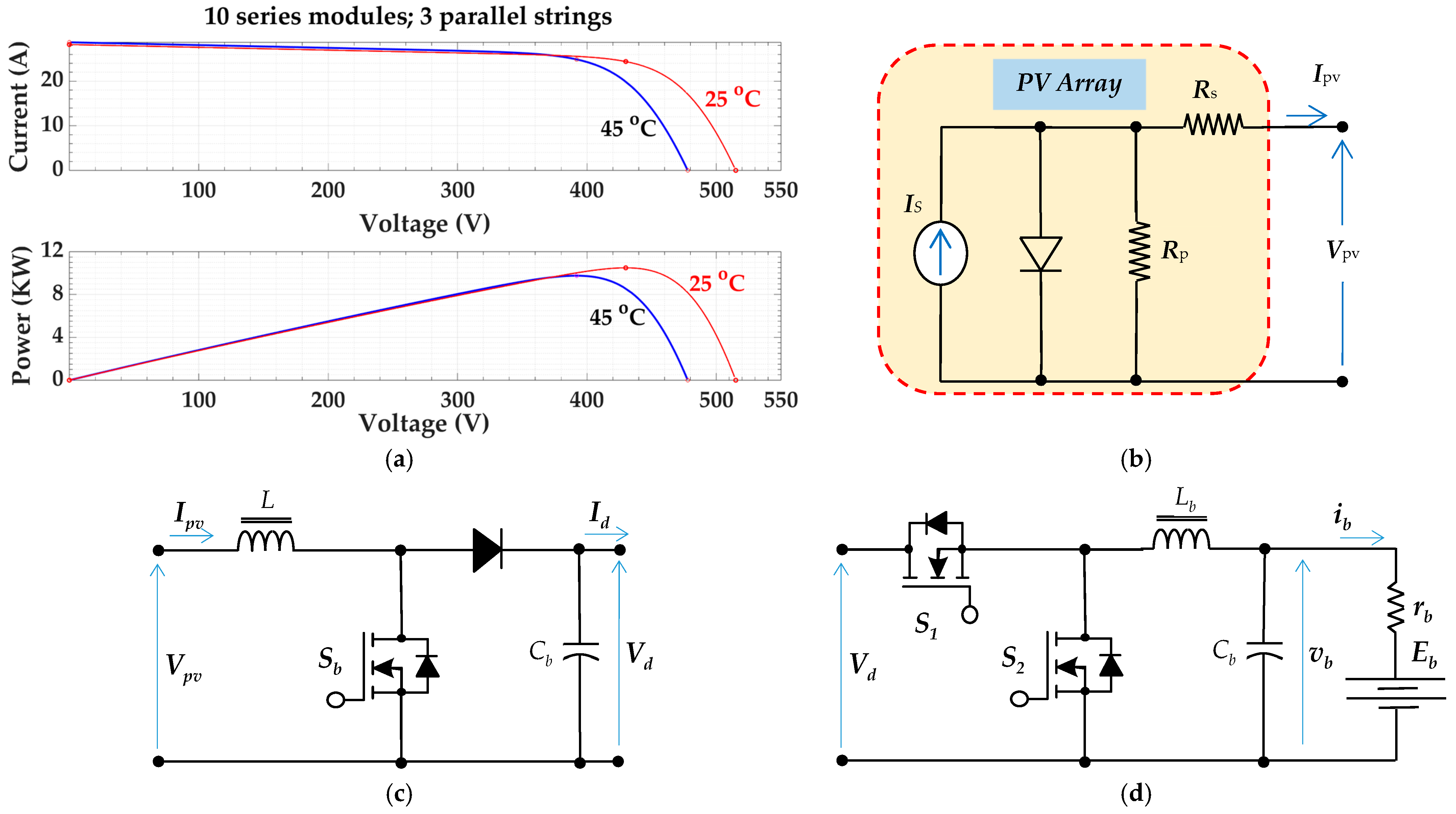
The electrical performance of the PV panel is displayed in Figure 2a. The comprehensive PV array model may be found in [33]. Nonetheless, Figure 2b displays a simplified and quite realistic representation of the PV panel.
The PV’s output voltage and current are denoted by Vpv and Ipv, panel corresponding parallel and series resistances by Rp and Rs, and short circuit current by IS. From the PV characteristics, it can be understood that the PV output power is maximum with certain load conditions. If we adjust the PV load to this condition, maximum power can be captured with the optimum utilization of the PV array. This loading condition can be adapted using a simple step-up DC/DC converter, shown in Figure 2c. We denoted this converter as the MPPT converter. The terminals of the DC bus is linked to the chopper’s output, while the PV terminals serve as its input. For this converter, several models have been developed; nevertheless, the average model is the most straightforward and appropriate for our situation. The average model of a step-up DC/DC converter operating in the continuous mode is shown in [34] as follows:
V d I d =   1 1 d 1 0 0 1 d 1 V p v I p v ,
where (d1) is the switch duty ratio, and (Id, Vd) are the DC link average current and voltage.
The boost converter of the PV should undergo modifications necessary to achieve MPPT conditions for the best photovoltaic energy utilization. For the PV boost converter, the well-liked and extensively applied MPPT method known as perturb and observe has been adopted. It has the benefits of a straightforward implementation and an easy algorithm. The MPPT control unit outputs the boost converter’s duty cycle value. In the literature, the algorithm is widely recognized [35].

2.2. Battery Bank Storage System

The suitable and acceptable model of the energy storage battery is an ideal DC voltage source (Eb) with a series internal resistance (rb). Actually, the internal voltage or the open circuit voltage is a nonlinear function of its state of charge (SOC). The SOC can be determined by [36]:
S O C b = S O C 0 + η i b Q n d t ,
where (SOCb, SOC0) is the battery SOC and its initial value, Qn is the battery capacity, and η is the coulombic efficiency.
However, as Figure 2d illustrates, the energy storage battery is managed using a bidirectional DC/DC converter. The bidirectional converter’s modeling, analysis, and operation all incorporate the unidirectional converter. To function, the converter must be in continuous mode. Two transistors (S1, S2) with their protecting diodes, and a filter comprised the managing converter. The converter connectors are linked to the DC link and the storage battery. A high inductance value is selected for the filter inductor so as to provide enough energy to charge and discharge the ESS battery. Consequently, the mode of operation of continuous conduction is guaranteed. The converter operates in two modes: boost mode and buck mode. While switch S1 functions as a diode and S2 is in boost mode of operation, the battery is discharged via the bidirectional converter. However, once S1 is started and S2 serves as a diode, it operates in the buck mode of operation, which is the battery charging mode. The converter’s state-space model is provided as follows:
x ˙ = A x +   B S   +   D ,
x = v b i l ,    A = C b 1 ( C b r b ) 1 0 L b 1 ,    B = 0 V d / L b ,    S = S 1 i n   B u c k   m o d e S 2 i n   B o o s t   m o d e ,
D = E b ( C b r b ) 1 ( V d / L b ) m ,   m = 0 f o r   B u c k   m o d e   1 f o r   B o o s t   m o d e ,   S k = 1 S k   i s   o n 0 S k   i s   o f f ,   k = 1   o r   2 ,
where (vb) is the battery terminal voltage, (m) is the mode factor, and (Cb, Lb) are the electrical circuit parameters of the filter presented in Figure 2d.

2.3. Supercapacitor Energy Storage System

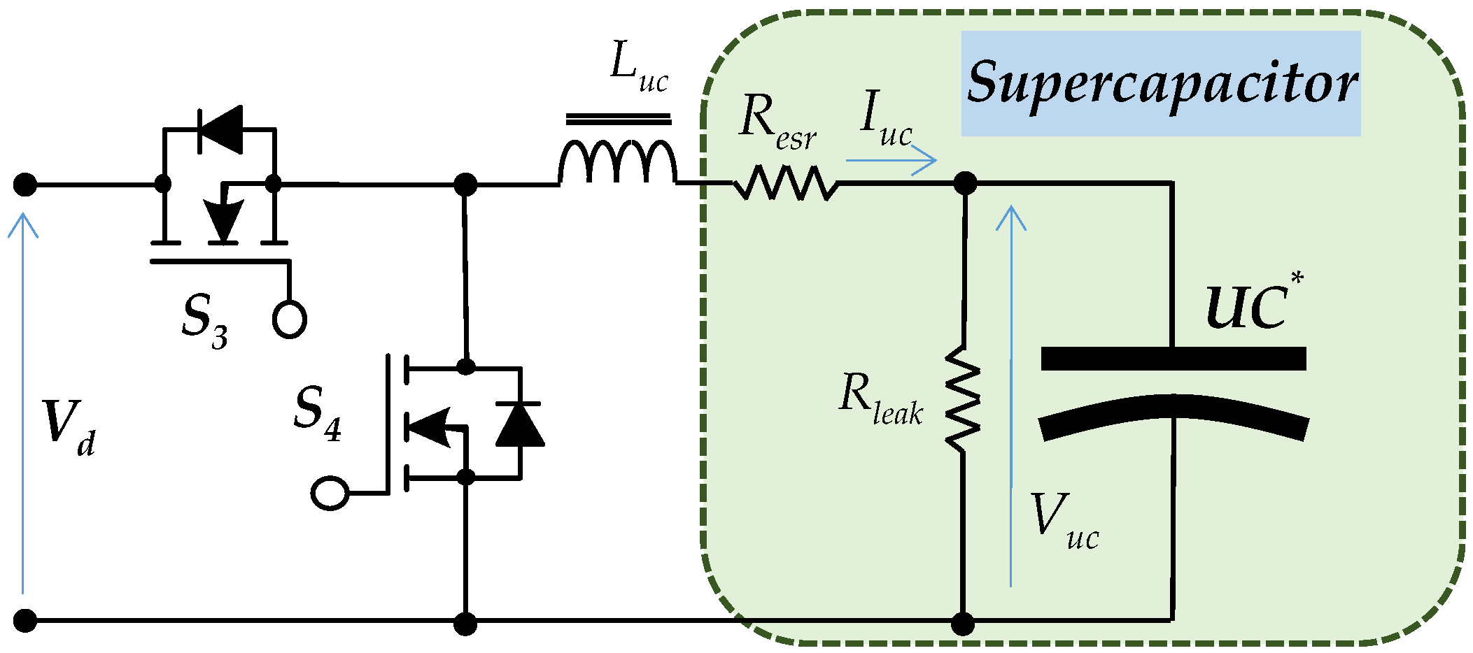
A nonlinear function of terminal voltage may be used to characterize the effective capacitance of supercapacitors [37]. Nonetheless, Figure 3’s simplified model was employed in this investigation. The series resistance, the effective capacitance (C), and the leakage resistance Rleak and Resr terms can be calculated from manufacturer data or by measurement. Next, the supercapacitor voltage is explained as follows:
V u c = 1 C * ( I u c V u c R l e a k ) d t +   I u c R e s r ,
where (Vuc, Iuc) is the supercapacitor terminal voltage and current, and (Resr, Rleak) are the electrical circuit parameters of the supercapacitor presented in Figure 3.
After determining the needed supercapacitance, the standard supercapacitor modules were then utilized to configure capacitance combinations in parallel and series connections. The stocked energy and power of the supercapacitor are provided by:
E u c = 0.5 C * V u c 2 ,    P u c = V u c I u c .
The supercapacitor converter is presented in Figure 3. It is typically the same as that of the battery converter. It differs only in the circuit parameters and switching sequence of the transistors. When the duty cycle of (S3) is larger than 50%, it will suck energy and charge. In other places, if the duty cycle ratio is of (S3) less than 0.5, the supercapacitor will discharge to provide the stored energy to the DC link.

3. Proposed Fractional-Order Frequency-Decomposed Control for DC Microgrids

When a disturbance occurs in the load power—whether an increase or decrease—it creates an imbalance between the produced and the demanded power in the DC microgrid. This mismatch directly impacts the DC bus voltage, causing oscillations or even leading to instability if the disturbance is significant. A similar effect occurs if the load power remains constant but one of the distributed generators (DGs) experiences a sudden change in its output due to environmental conditions (e.g., solar PV dropping under cloud cover) or an unexpected disconnection from the DC microgrid. To mitigate these issues, an ESS is integrated into the DC microgrid to stabilize the DC link voltage in the various disturbances. The ESS achieves this by either absorbing excess power or supplying additional power to the DC bus, ensuring voltage regulation. This control is typically implemented through a DC-DC converter, where the duty cycle is dynamically adjusted by a DC link voltage regulator to maintain system stability.

3.1. Conventional FBC Using the PI Controller

A hybrid ESS (HESS), combining BESS and SC, offers enhanced performance, where the supercapacitors provide rapid power delivery to handle transient disturbances, preventing high current stress on the batteries, while the batteries handle sustained power demands for long-term stability. This approach extends the battery lifespan by avoiding frequent high-current charge/discharge cycles assigned by the controller. In conventional control strategies for hybrid ESS, frequency-based power splitting is commonly employed, as illustrated in Figure 4. This method assigns high-frequency power fluctuations to the UC and low-frequency variations to the batteries, optimizing system efficiency and response time.
The structure of the traditional FBC scheme used for DC link voltage stabilization is shown in Figure 4. This method uses a low-pass filter (LPF) and a high-pass filter (HPF) to separate the power demand from the load into distinct frequency components. The battery is given the low-frequency (slow-varying) power component because it is more appropriate for long-term energy delivery, and the supercapacitor is given the high-frequency (fast-varying) component because it can react quickly to abrupt load transients. By synchronizing the outputs of both energy storage devices, a voltage regulator makes sure that the DC link voltage is kept at its reference value. Although this method improves transient handling compared with single-storage systems, it lacks adaptability and optimal tuning, which may result in suboptimal voltage regulation under highly dynamic load and generation conditions.
The dynamic behavior of the DC bus can be described by the following differential equation:
C D C d v d c d t = i H E S S + i P V i l o a d ,
where Cdc is the equivalent DC bus capacitance, i H E S S is the current provided by the hybrid energy storage systems, iPV is the PV current, and iload is the load current drawn by the DC loads across the DC bus.
The HESS current includes the contribution from the BESS (i.e., i B E S S ), which can either supply or absorb battery current, depending on the power balance, and the supercapacitor via its current i U C such that:
i H E S S = i B E S S + i U C .
In the present study, the outer voltage control loop is shared between the battery and the UC. After calculating the DC link voltage error ( e d = v d * v d ) in the outer loop of the control, the reference current for the hybrid ESS ( i h e s s * ) is a result of the voltage loop based on the PI controller. The hybrid energy storage systems of BESS and UC must supply this current to regulate the DC link voltage at its setpoint. The relationship is expressed as
i h e s s * = K × e d + K × e d   d t ,
where Kp and Ki are the proportional and integral gains of the PI controller responsible for the DC link voltage stabilization. v d * is the reference DC link voltage, and v d is the measured DC link voltage.
The mismatch between the load demand and PV generation current can be viewed as a system disturbance, for which the HESS must compensate. Next, the generated reference current of the HESS ( i h e s s * ) is decomposed into two components, which are the low-frequency component ( i b e s s * ) that will be handled by the BESS for sustained power balance. High-frequency component ( i u c * ) that will be managed by the UC for a rapid transient response. This decomposition is achieved using a first-order LPF with a time constant (τ) as follows:
i b e s s * = 1 1 + τ s i h e s s * ,
i s c * = i h e s s * i b e s s * = τ s 1 + τ s i h e s s * ,
where the Laplace operator is (s).
As shown in Equation (11), the supercapacitor appears to be filtered using a HPF that has the same (τ) as the first-order LPF. This configuration ensures that the supercapacitor primarily responds to the high-frequency components of system disturbances, effectively managing rapid transient events.
The generated current references for the BESS and UC are individually regulated through their respective inner control loops, each implemented using a PI controller. To enhance dynamic performance, a modification is introduced wherein the error signal from the BESS current control loop is supplied into the UC current control loop. This enables the faster energy storage device (i.e., UC) to assist in compensating for the tracking error of the BESS, thereby improving the system’s responsiveness to power mismatches [38]. Also, the voltage regulation error is injected into the supercapacitor current control loop via gain ksc, allowing the UC to dynamically enhance the system’s transient response. Since the associated DC-DC converters are bidirectional, the reference currents can take on positive or negative values depending on the instantaneous power imbalance. Ensuring a stable DC-link voltage remains a critical objective, especially in the context of electric vehicle charging, where consistent terminal voltage is essential for reliable and efficient operation.

3.2. Proposed FBC Using the Fractional-Order PI Controller

Fractional calculus in control systems allows for more precise modeling and tuning than traditional methods. By using non-integer orders of integration and differentiation, controllers can better represent complex dynamics like memory effects and viscoelasticity [39]. This adaptability leads to finer tuning of system responses and enhanced control performance across various operating conditions [40]. In addition, fractional-order control offers significant flexibility in representing numerical values and dynamic system behavior. The core idea is a unified mathematical function that links fractional-order differential and integral operators. This function depends on a specific fractional order, denoted as q. By adjusting q, the controller can smoothly transition between traditional integer-order control behaviors and more refined, nuanced responses. A fractional-order system is categorized as a differential transfer function as its order, q, is greater than zero (q > 0). Conversely, it’s considered a 1st order integral if its order q is less than zero (q < 0). Also, the relationship between the differential and the integral operator of the FO can be mathematically expressed by:
D l b , u b q f ( t ) = d q d t q   f ( t ) q > 0 f ( t ) q = 0 l b u b f ( t ) d τ q q < 0 ,
where lb refers to the lower band and ub indicates the upper band.
The conceptualization of fractional order, particularly its physical manifestations, often presents significant challenges. Consequently, a substantial body of literature is dedicated to elucidating this intricate concept. Among the various definitions, the Riemann–Liouville approach offers a fundamental method for calculating the fractional derivative of a certain variable, thereby [41]:
D l b , u b q f ( t ) = 1 Γ ( n q ) d d t n l b u b f ( τ ) ( t τ ) q n + 1 d τ ,
where n − 1 < q < n, n ∈ N, and the Gamma function Γ w is given as
Γ ( w ) = 0 e t t w 1 d t .
The Riemann-Liouville fractional derivative, as presented in Equation (14), can be transformed into the result of Equation (16) by means of the Laplace method. This offers one way to approach fractional calculus. Another significant perspective comes from Caputo’s definition, which offers a second clarification of the FO concept. Specifically, Caputo’s approach is valuable for representing the q-order of a function f(t) in the time domain, as detailed in Equation (17). This suggestion broadens our understanding of FO, enabling a more comprehensive analysis of functions with fractional orders [25].
L D 0 q f ( t ) = s q F ( s ) z = 0 n 1 s z ( D 0 q z 1 f ( t ) ) | t = 0 ,
D l b , u b q f ( t ) = ( d d t ) n f ( t ) q = n l b u b f n ( τ ) ( t τ ) 1 n + q d τ Γ ( n q ) 1 n 1 < q < n .
Upon performing the Laplace transformation to Equation (16), the resulting integral order necessitates a specific initial condition. This initial condition carries physical significance, which can be further clarified by referencing Equation (18),
L D 0 q f ( t ) = F ( s ) s q z = 0 n 1 f ( z ) ( 0 ) s q z 1 .
Implementing FO operators in the time domain requires complex mathematical computations. To address this, the recursive approximation technique is frequently utilized for its practical implementation [42]. The Laplace transformation offers an alternative mathematical representation for the qth derivative, as
s q K k = N N s + ω k s + ω k 1 ,
where
K = ω h q , ω k = ω b ω h ω b k + N + ( 1 q ) / 2 2 N + 1 , ω k = ω b ω h ω b k + N + ( 1 + q ) / 2 2 N + 1 ,
Within the effective frequency range [ ω b , ω h ], which can be selected as [−1000, 1000] rad/s, N is the Oustaloup method’s approximation order. We have decided to use the value of N, or five, in this work.
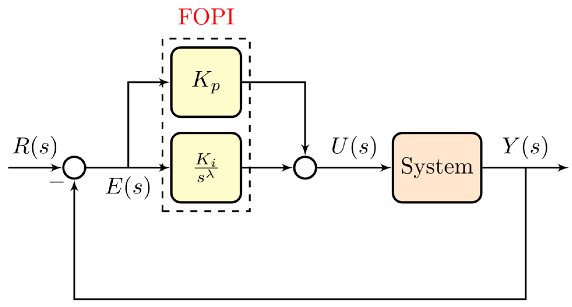
In this paper, we utilized a FOPI controller characterized by three key tuning parameters: proportional gain (Kp), integral gain (Ki), and the fractional integral order (λ). Controllers designed with these parameters have shown superior performance in terms of stability, transient response, and overall accuracy when compared to conventional PI controllers. Furthermore, the FOPI regulator exhibits greater robustness and adaptability against system disturbances, making it well-suited for handling a variety of operational circumstances. Figure 5 illustrates the basic configuration of the control system, while Equation (20) provides the complete Laplace-domain transfer function of the FOPI controller, signified as Gc(s), with λ typically ranging between 0 and 1.
G c ( s ) = K p + K i 1 s λ .
The DC bus voltage is continuously observed and compared against a predefined set value, v d c * , to maintain stable operation. The fractional-order proportional-integral (FOPI) controller plays a serious role in this regulation by processing the voltage error and generating the corresponding HESS reference current, i h e s s * , which serves as a control input for the HESS, as shown in Figure 6. This relationship is formalized as
i h e s s * = K p v + K i v 1 s λ v v d * v d ,
where Kiv, λv, and Kpv are the integral gain, fractional order, and proportional gain of the voltage loop controller. The fractional integral operator s λ v provides enhanced robustness and dynamic response compared to classical integer-order controllers.
The FOPI regulator also regulates the current of the bidirectional DC/DC converter connected to the BESS and UC (i.e., in the inner loop control), adjusting it based on the error signals to track the desired current reference accurately by generating the duty cycle. The duty cycle control for the UC can be expressed as in (22). While for the BESS, the duty ratio is directly produced by the PIbess regulator, limited to the range of [0 1]. Furthermore, the dual-loop control architecture inherently ensures that the current drawn from the BESS remains within predefined safety limits, ibess,minibessibess,max, thus providing critical protection against overcurrent conditions and prolonging the device’s lifespan. This safety constraint can be incorporated via saturation functions or current limiters within the control loop.
D u c ( t ) = D 0 + d u c ,
D 0   is the nominal duty cycle that equals 0.5, which is the threshold between the buck and boost modes of the DC-DC converter.
Traditionally, the parameters of the proposed FOPI controller are determined using trial and error—a method that relies deeply on practitioner proficiency and can be difficult to implement effectively. Accurate tuning of all FOPI parameters is crucial to improve system performance and maintain stability under disturbances. To achieve optimal parameter tuning, a metaheuristic optimization approach using the Grey Wolf Optimizer (GWO) can be applied. The final parameters of the proposed FBC using the FOPI are summarized in Table 1. The suggested FOPI-based control approach has several drawbacks, even though it performs better in dynamic response, voltage regulation, and energy management. The primary disadvantage is that, because of the fractional-order operator and the optimization-based parameter tuning procedure, it has a comparatively higher computing complexity than traditional PI controllers. Furthermore, suppose the controller is not correctly tuned. In that case, its performance may be sensitive to parameter changes, and its use in real-time systems may necessitate discretization approximations or higher processing power.

4. Simulation Results and Discussion

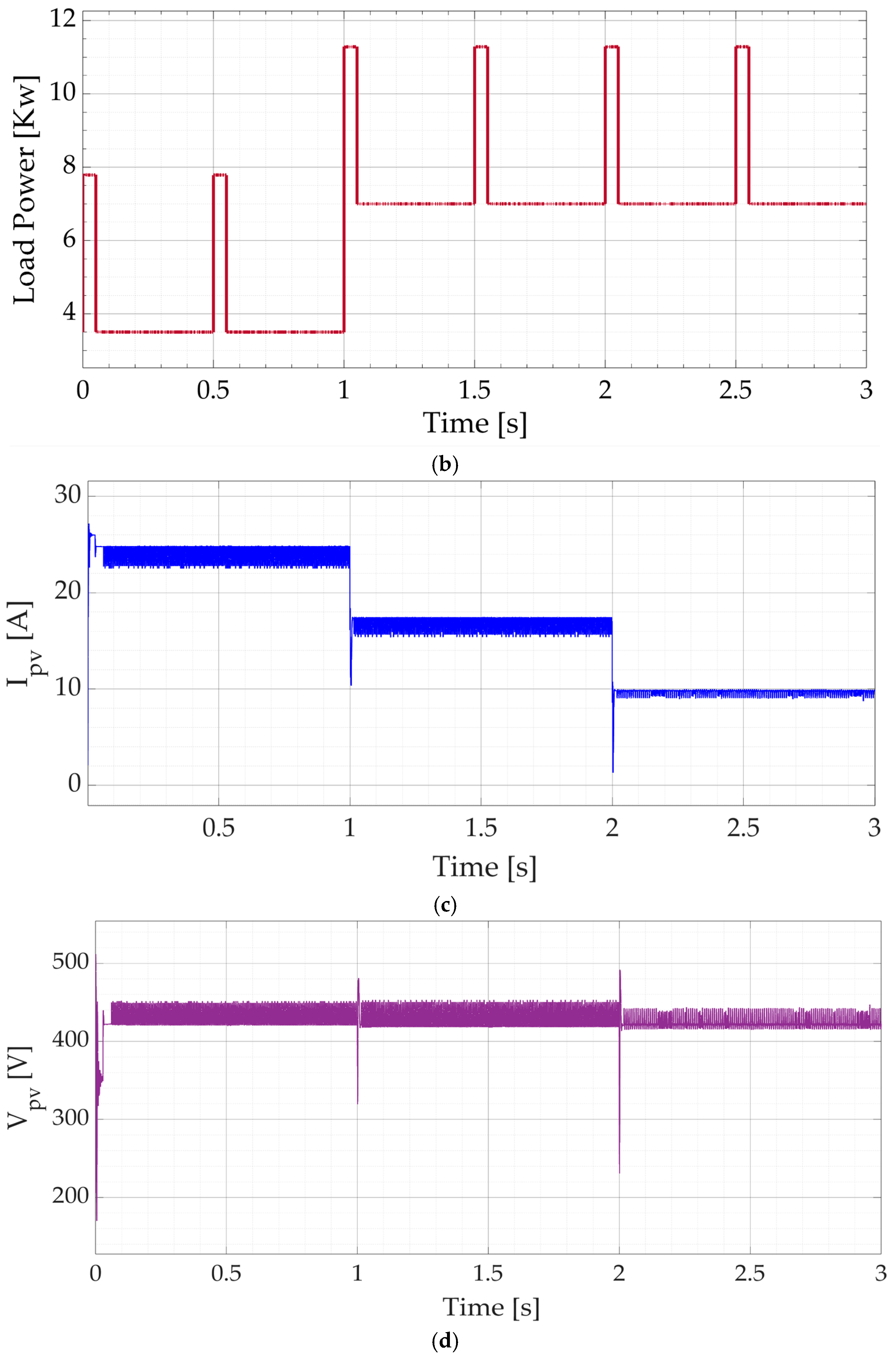
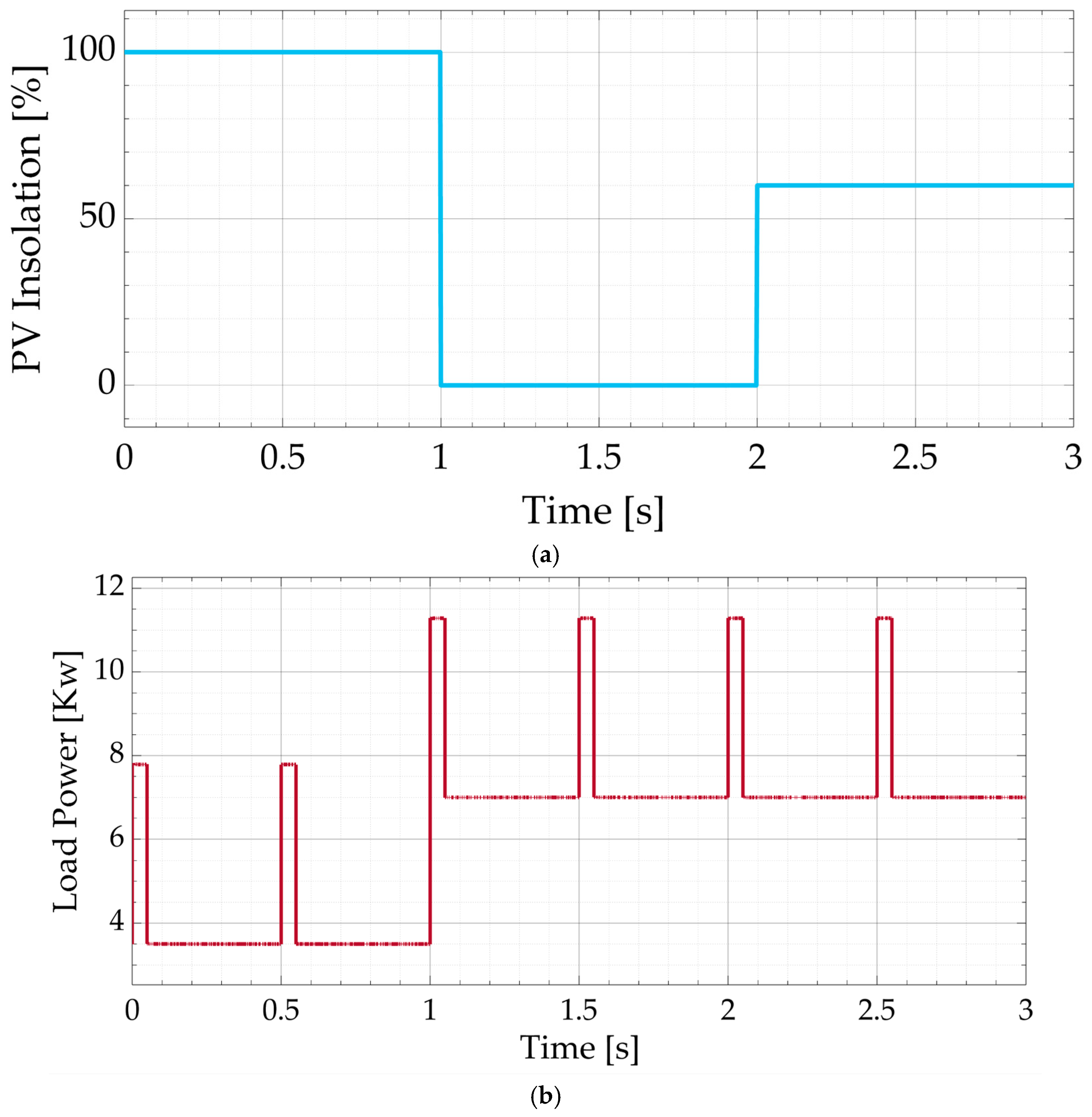
Using computer simulations, the recommended power system with the best regulator, shown in Figure 1, has been verified. The MATLAB software (version R2023a) has been utilized to model and assess this microgrid to demonstrate the usefulness of the suggested method for facing variations in load power and PV insolation. The microgrid’s parameters were designated as follows: the PV panel (Voc = 5150 V, Isc = 28.2 A, Pmax = 10.488 kW); the battery (lead acid, 500 V, 500 AH); DC-link voltage (700 V); and UC (1000 F, 900 V). The responsiveness of the microgrid with the proposed controller has been examined with varied loads and PV insolation in steps, as shown in Figure 7a,b. The results are classified into two scenarios. In scenario #1, both the PV insolation and the pulsed DC load vary. While scenario #2 simulates the system response with a PV panel fault that resembles a completely shaded PV. The scenarios have been adapted to assess the effectiveness of using the suggested microgrid with the optimal FOPI controller compared to the traditional PI controller. The detailed findings and discussions are presented in the following subsections.

4.1. Scenario #1 (Sufficient but Variable PV Energy with Dynamic Load)

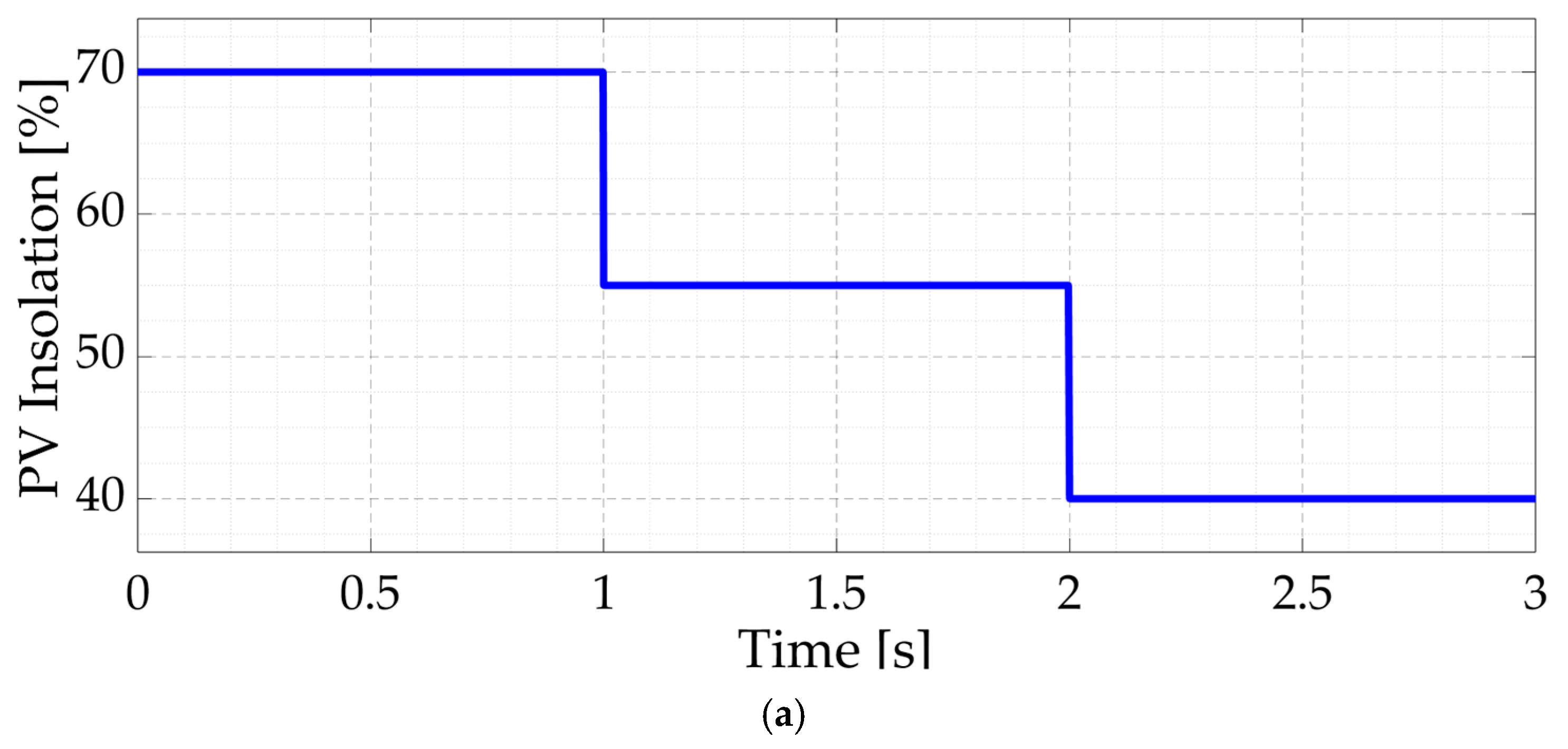
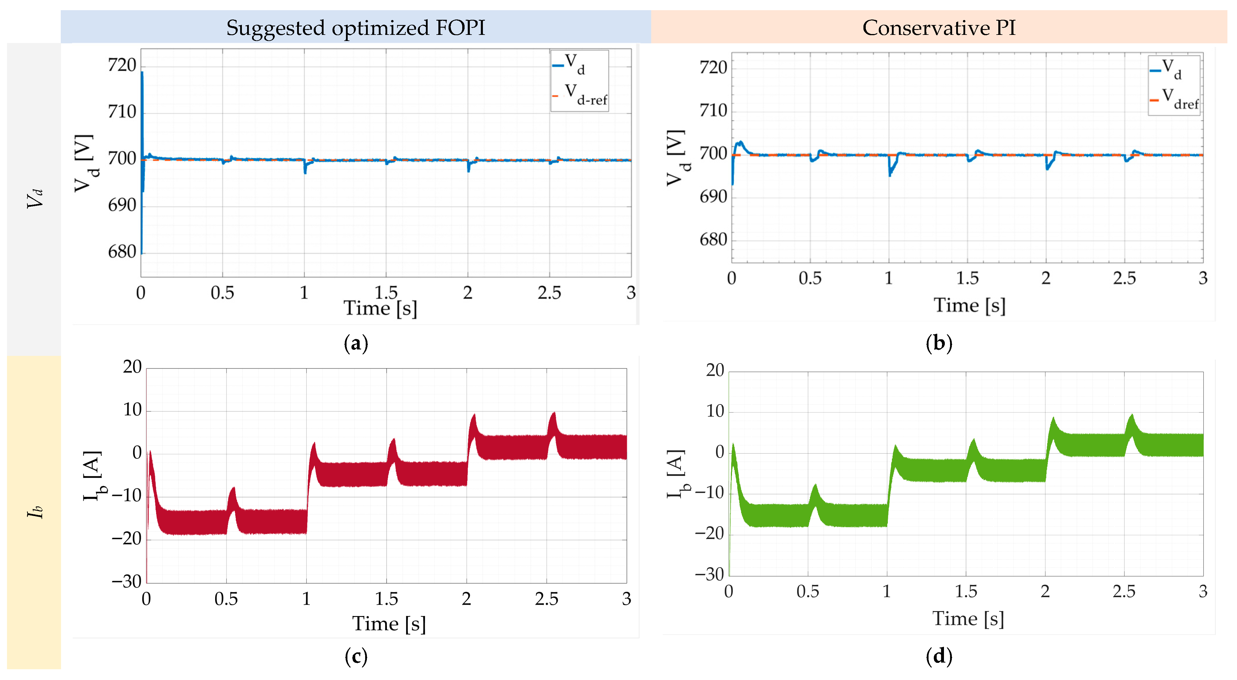
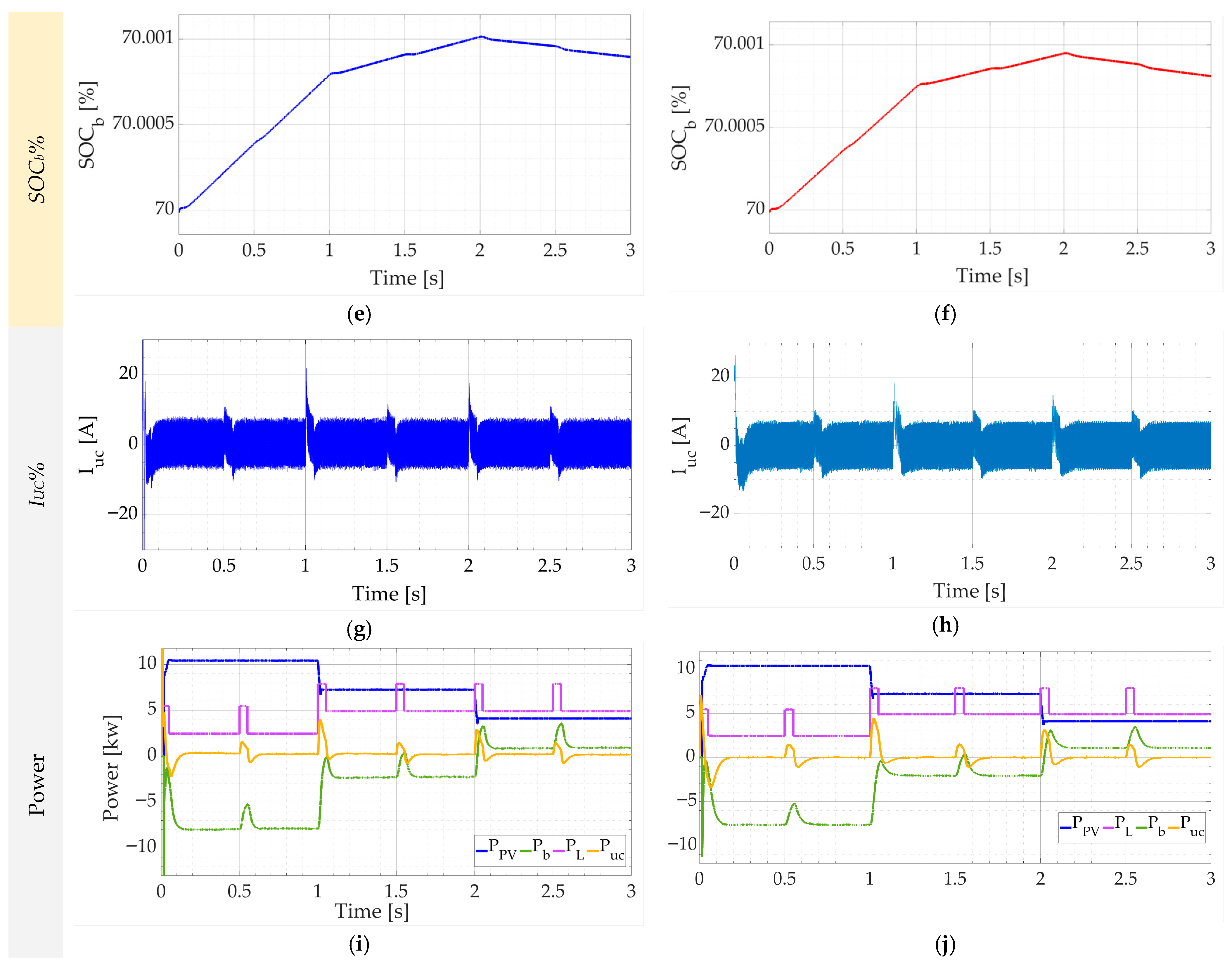
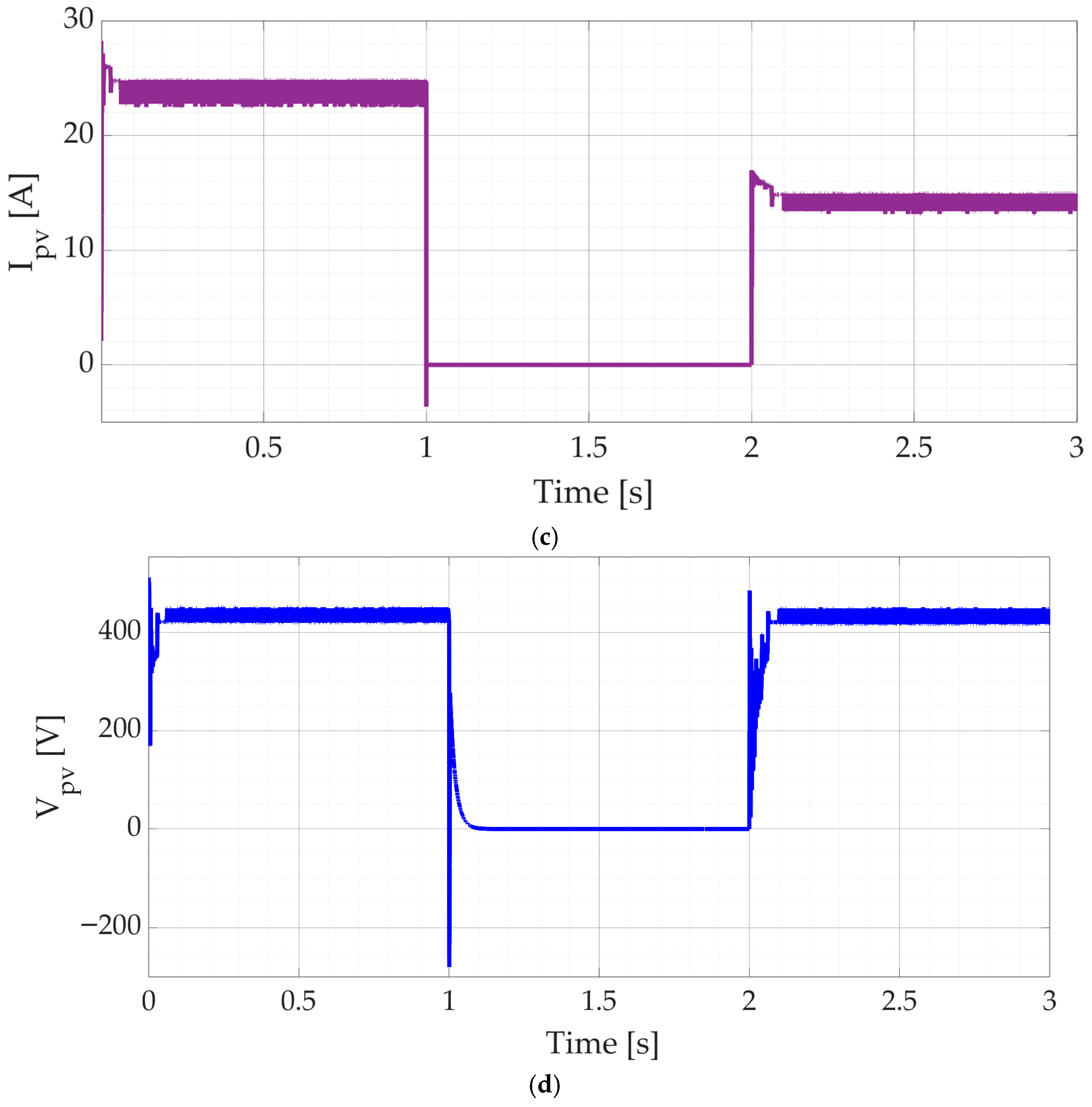
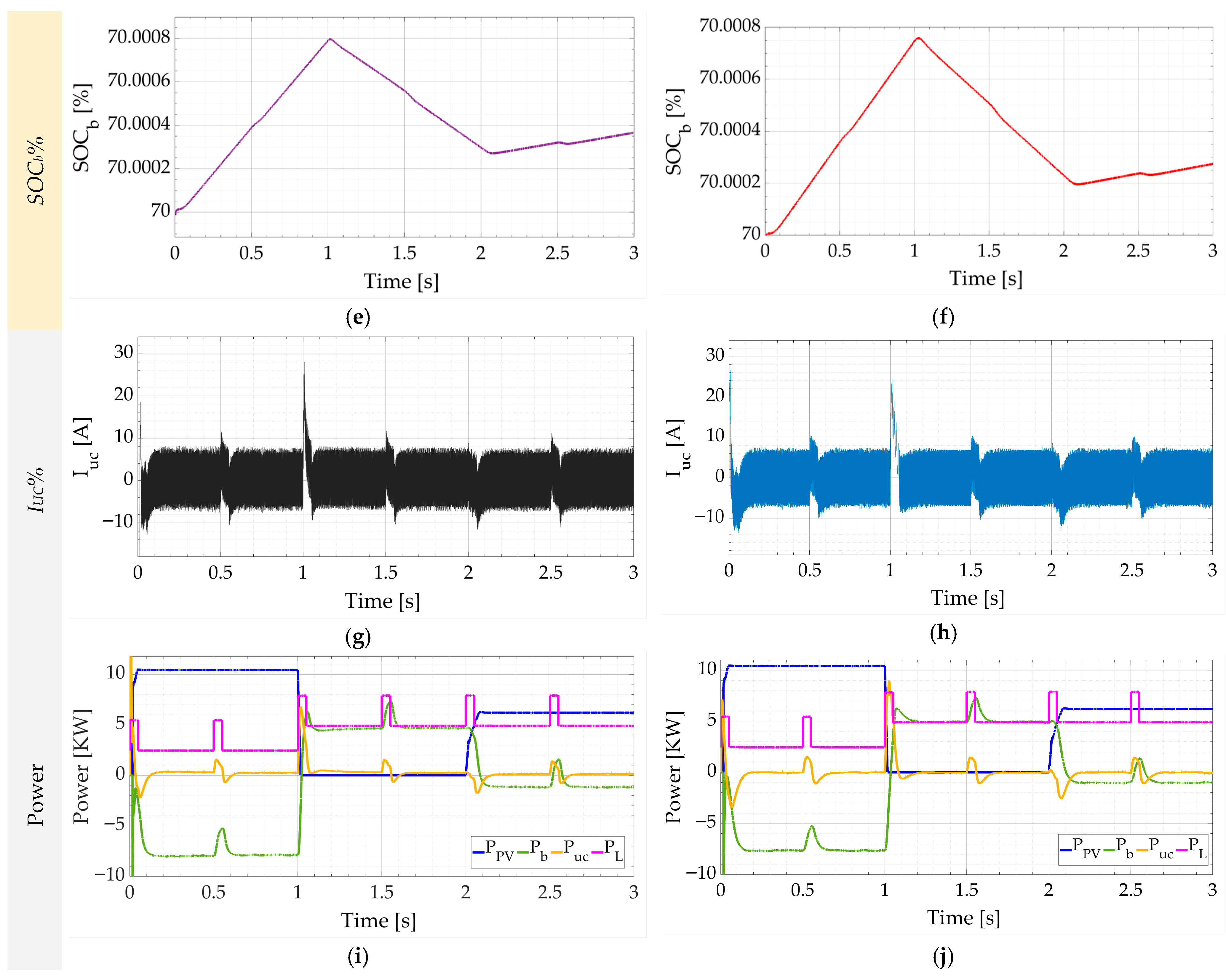
In this scenario, the microgrid has been exposed to step fluctuations in the PV insolation, as displayed in Figure 7a. The insolation has been saved at 70% for the first second period, decreased to 55% during the next second period, and decreased to 40% for the third second. Also, the DC load has step and pulsed variations, as presented in Figure 7b. The PV current and voltage during those conditions are illustrated in Figure 7c,d. The PV’s MPPT state is tracked by the voltage and current measurements, as shown by Figure 2a’s characteristics. The simulation results of the proposed system with scenario #1 are shown in Figure 8. As illustrated in Figure 8a,b, the microgrid’s bus-voltage response is shown for both the proposed optimal FOPI controller and the traditional PI controller. In both cases, the controllers could maintain the DC bus voltage at its specified reference level. Nevertheless, it is obvious that the DC link voltage performance using the optimal FOPI regulator is better than that with the traditional PI regulator. The settling times are shortened by ≅40% and overshoots are improved by ≅50%. Figure 8c,d present the storage battery current using both controllers. The responses are identical. It is also noted that the battery current value and polarity illustrate the charging and discharging required by the battery to balance the energy gap among the PV panel and the demanded load. During the first second, the battery charges, as there is excess energy from the PV after supplying the load power. In the next second, the PV generated energy dropped; however, it still greater than the load demand. Hence, the battery charges with a lower battery current. During the final second, the PV power dropped greatly (40%) and cannot supply the load demand itself. Therefore, the battery discharges to support the energy decrease and its current changes its direction. The battery’s state of charge (SOC) employing both controllers is shown in Figure 8e,f. In both situations, SOC’s responses are remarkably close to each other. Figure 8g,h compare the UC’s current response using both controllers. Also, the curves are remarkably close to each other. In both cases, the average UC current is zero except at the pulsed load instants. At those instants, the UC current charges or discharges to damp the DC bus transient oscillations. Figure 8i,j show all powers in the microgrid consuming the two regulators with the proposed system. The UC’s power is zero except at the transients or pulsed load variations. To enhance responsiveness and control the microgrid’s energy condition, the UC’s power is combined with the battery power. The two controllers have the same overall powers.

4.2. Scenario #2 (Fault in the PV with Dynamic Load)

In this scenario, the PV insolation has been dropped to zero according to completely shaded PV, as shown in Figure 9a. The insolation was kept at 100% for the first second period, decreased to 0% during the next second period, and increased to 60% for the third second. Also, the DC load variations are identical to that of scenario #1, as presented in Figure 9b. The PV current and voltage during those conditions are presented in Figure 9c,d. The current and voltage values track the MPPT status of the PV indicated by the characteristics of Figure 2a. Figure 10 displays the outcomes of the suggested system’s simulation using scenario #2. Figure 10a,b show the bus-voltage response of the microgrid for both the traditional PI controller and the suggested ideal FOPI controller. The controllers were capable of keeping the DC link voltage at the designated reference value in both situations. However, it is clear that the optimum FOPI controller performs better in terms of DC bus voltage than the traditional PI controller. Overshoots are improved by ≅50% and settling times are reduced by ≅40%. The storage battery current employing both controllers is shown in Figure 10c,d. The answers are almost the same. Additionally, it should be mentioned that the battery’s current value and polarity show how much charging and discharging the battery needs to do to make up for the energy difference between the PV panel and the load. After providing the load power, the PV produces extra energy, which is used to charge the battery during the first second. The PV’s energy output fell to zero in the following second, making it unable to continue meeting the load requirement. As a result, the battery drains with less current. The PV power rose to 60% in the last second and was able to meet the load requirement on its own. As a result, the battery’s current changed direction and charged to absorb the extra energy. Figure 10e,f display the battery’s state of charge (SOC) using both controllers. The comments from SOC are quite similar in both cases. The UC’s current response utilizing both controllers is compared in Figure 10g,h. The bends are also rather near to one another. Apart from the pulsed load instants, the average UC current is zero in both scenarios. In order to reduce the transient oscillations of the DC bus, the UC current charges or discharges at certain moments. Using the two controllers and the suggested approach, Figure 10i,j display all of the microgrid’s powers. Except for transients or pulsed load changes, the UC’s power is zero. The electricity from the UC is coupled with the battery power to enhance responsiveness and regulate the energy situation of the power system. The combined powers of the two controllers are equal.
To compare mathematically the controllers’ performance, an objective function is adapted. The least square error (LSE) of the DC bus voltage is selected for this purpose. It has been calculated for both controllers during each scenario. It has been found that the LSE is lower with the proposed optimal controller by ≅80%. A comparison and summery of the results are given in Table 2.
Compared to current techniques, the suggested frequency-decomposed FOPI approach has several benefits. In comparison to traditional PI controllers, it achieves better transient performance by combining frequency-based power splitting with fractional-order control, reducing overshoot by roughly 50% and settling time by roughly 40% [32]. The Least Square Error (LSE) of the DC bus voltage is reduced by about 80% as a result of the utilization of GWO optimizer, which further guarantees ideal parameter tuning. Furthermore, battery stress is greatly decreased by coordinating battery and supercapacitor control, which enhances system dependability and prolongs storage life [26,30]. The suggested approach strikes a realistic balance between robustness, performance, and implementation complexity when compared to Model Predictive Control (MPC), which provides excellent dynamics but necessitates a high computational effort [23] and Sliding Mode Control (SMC), which is robust but suffers from chattering effects [5]. The method’s drawbacks, however, are the computational and mathematical difficulty of fractional-order operators, the requirement for approximation in real-time hardware implementation, and the extra offline work needed for metaheuristic optimization.
Notwithstanding these drawbacks, the suggested FOPI approach outperforms traditional PI, droop-based, and filter-based techniques and offers a useful and efficient improvement in stabilizing DC microgrids with hybrid energy storage [22]. A summary of this comparative analysis has been included in the revised manuscript as Table 3.
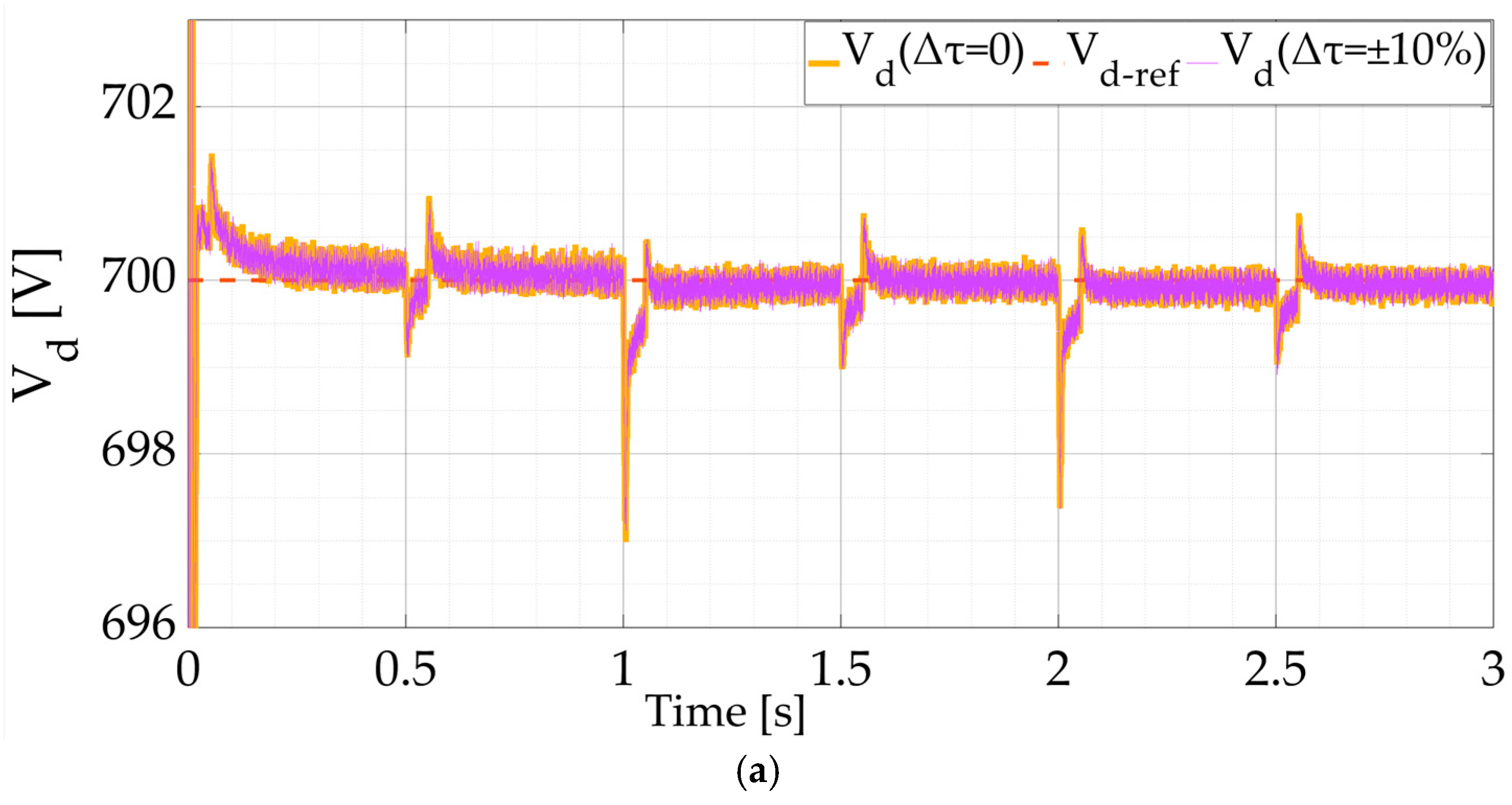
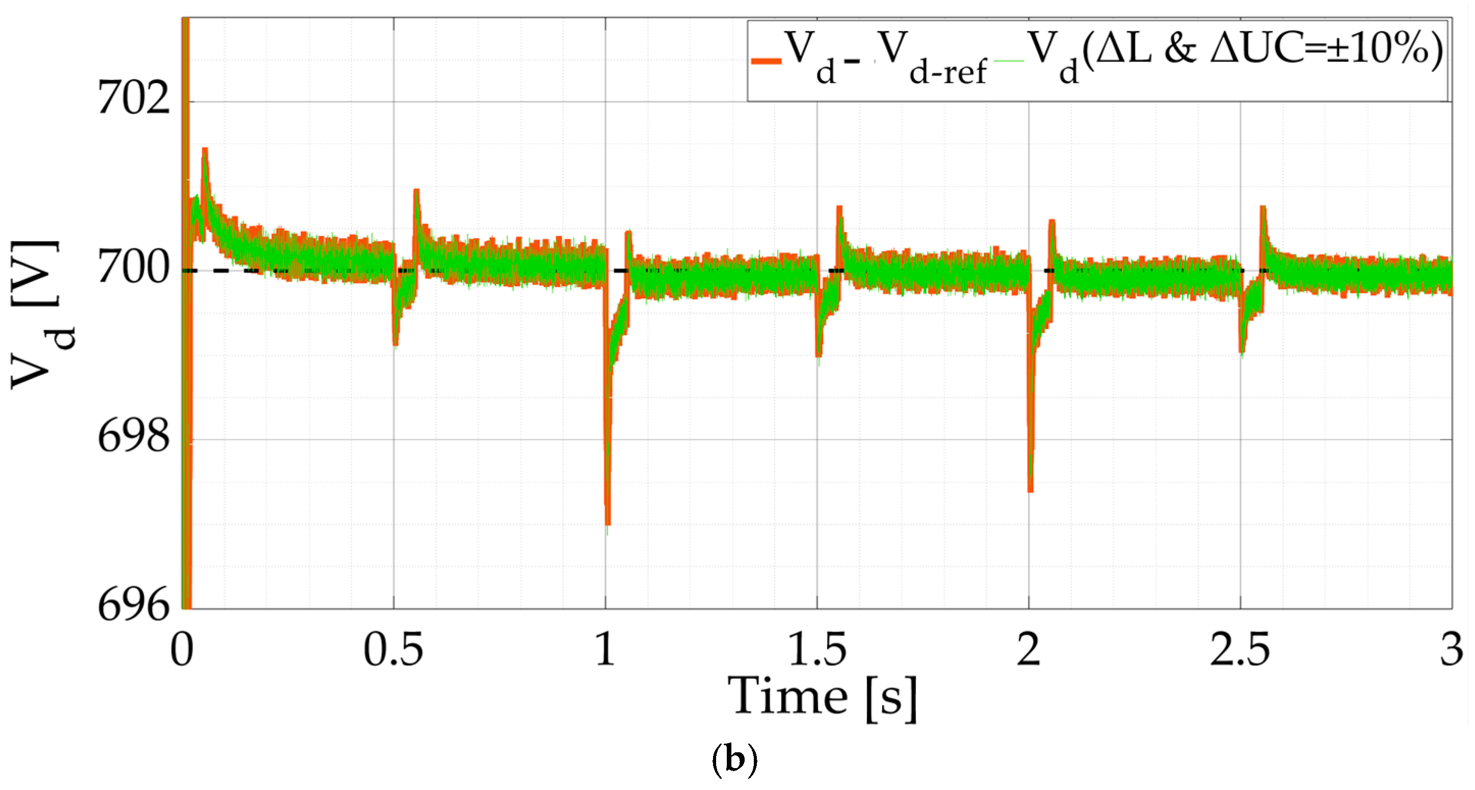
To validate the robustness of the optimized controller, some variations (±10%) have been adapted to the LBF time constant (Δτ), the UC value (ΔCUC), and the inductance of the UC converter (ΔL). The response of the DC bus voltage is indicated at Figure 11a,b. It can be emphasized that the proposed control system is robust against parameter variations.

5. Conclusions

To achieve stability of the DC bus voltage in a DC microgrid, this work presents a decomposition control technique that makes use of the optimum FOPI. Variations in PV insolation levels, which result in intermittent power generation, were successfully lessened using a hybrid energy storage system that included a UC and a battery. Two loops make up the suggested control system for the UC and battery: an inner loop that utilizes the optimal FOPI to manage the UC and battery currents, and an outer control loop that customs the FOPI regulator to control the DC bus voltage. The GWO procedure is used to optimize the settings of FOPI to attain the best possible performance. An optimal FOPI and a conventional PI controller were used to compare the outcomes under the identical circumstances. It was discovered that the microgrid with the best FOPI controller outperformed the one with the PI controller. The results show that by efficiently coordinating power sharing with the supercapacitor, the suggested approach improves DC bus voltage control, lowers overshoot and settling time, and diminishes battery stress. Furthermore, as compared to the traditional PI-based system, the objective function is reduced by 80% when the suggested optimum FOPI is implemented. These results illustrate the effectiveness of frequency decomposed fractional-order control as a dependable choice for next-generation DC microgrids with hybrid energy storage. Future research could involve applying different optimization techniques for parameter tuning and experimentally validating the suggested controller using hardware-in-the-loop or laboratory-scale prototypes. The method’s scalability to larger hybrid AC/DC microgrids and incorporation of adaptive or machine learning-based control strategies for increased autonomy could all be explored in future extensions.

Author Contributions

Conceptualization, S.A.Z. and A.B.; Methodology, S.A.Z. and A.B.; Software, S.A.Z. and A.B.; Validation, H.A.; Investigation, A.B.; Data curation, H.A., H.M.E.-H. and A.W.; Writing—review and editing and Writing—original draft, H.M.E.-H.; Supervision, H.A. and A.W.; Project administration, A.W.; Funding acquisition, H.M.E.-H. All authors have read and agreed to the published version of the manuscript.

Funding

This article is derived from a research grant funded by the Research, Development, and Innovation Authority (RDIA)—Kingdom of Saudi Arabia—with grant number (13385-Tabuk-2023-UT-R-3-1-SE).

Institutional Review Board Statement

Not applicable.

Informed Consent Statement

Not applicable.

Data Availability Statement

Data are contained within the article.

Acknowledgments

The authors extend their appreciation to the Research, Development, and Innovation Authority (RDIA), Saudi Arabia for funding this work through Grant number (13385-Tabuk-2023-UT-R-3-1-SE).

Conflicts of Interest

The authors declare no conflicts of interest.

Nomenclature

Isthe short circuit current of the PV panel
d1the duty cycle of the step-up DC/DC 
(Vd, Id)the DC-bus voltage and current
(Vpv, Ipv)the PV output’s average current and voltage.
(Rs, Rp)the panel equivalent series and parallel resistances 
Ebthe battery’s open circuit voltage 
rbthe battery’s internal resistance 
(SOCb, SOC0)the battery’s state of charge and its initial value 
ηthe coulombic efficiency
vbthe battery terminal voltage
mthe mode factor
(Cb, Lb)the filter capacitance and filter inductance 
(Vuc, Iuc)the supercapacitor terminal voltage and current, and are 
(Resr, Rleak)the electrical circuit parameters of the supercapacitor
C*the effective capacitance of the supercapacitor
Eucthe energy of the supercapacitor 
Cdcthe equivalent DC bus capacitance
( i H E S S ,   i h e s s * ) the current provided by the hybrid ESS and its reference
iPVthe PV current
iloadthe load current drawn by the DC loads across the DC bus
( i U C ,   i u c * ) the supercapacitor current and its reference
( i B E S S ,   i b e s s * ) the BESS current and its reference
LPFthe low-pass filter 
τthe LPF’s time constant 
Kp and Kithe proportional and integral gains of the PI controller
( v d ,   v d * ) the DC link voltage and its reference
the approximation order of the Oustaloup method
λthe fractional integral order coefficient
Vdc_refReference DC bus voltage (V)
DDuty ratio of the DC/DC converter
fcCut-off frequency of the filter (Hz)
FOPIFractional-Order Proportional–Integral controller
GWOGrey Wolf Optimizer
HPFHigh-Pass Filter
ibBattery current (A)
iucUltracapacitor current (A)
LSELeast Square Error (performance index)
PbBattery power (W)
PloadLoad demand power (W)
PucUltracapacitor power (W)
QₙNominal capacity of the battery (Ah)
sLaplace operator
SOCState of charge of the battery
SOC0Initial state of charge
VdcDC bus voltage (V)
FOPIthe fractional-order proportional-integral 
FOthe fractional-order 
Kpv, Kiv, and λvthe proportional gain, integral gain, and the FO’s outer voltage loop control
Kpi, Kii, and λithe proportional gain, integral gain, and the FO’s inner current loop control

References

  1. Peters, R.; Berlekamp, J.; Kabiri, C.; Kaplin, B.A.; Tockner, K.; Zarfl, C. Sustainable Pathways towards Universal Renewable Electricity Access in Africa. Nat. Rev. Earth Environ. 2024, 5, 137–151. [Google Scholar] [CrossRef]
  2. Kartal, M.T.; Pata, U.K.; Alola, A.A. Renewable Electricity Generation and Carbon Emissions in Leading European Countries: Daily-Based Disaggregate Evidence by Nonlinear Approaches. Energy Strategy Rev. 2024, 51, 101300. [Google Scholar] [CrossRef]
  3. Wang, P.; Huang, R.; Zaery, M.; Wang, W.; Xu, D. A Fully Distributed Fixed-Time Secondary Controller for DC Microgrids. IEEE Trans. Ind. Appl. 2020, 56, 6586–6597. [Google Scholar] [CrossRef]
  4. Chaturvedi, S.; Fulwani, D. Adaptive Voltage Tuning Based Load Sharing in DC Microgrid. IEEE Trans. Ind. Appl. 2020, 57, 977–986. [Google Scholar] [CrossRef]
  5. Behera, M.K.; Saikia, L.C. A Novel Resilient Control of Grid-Integrated Solar PV-Hybrid Energy Storage Microgrid for Power Smoothing and Pulse Power Load Accommodation. IEEE Trans. Power Electron. 2022, 38, 3965–3980. [Google Scholar] [CrossRef]
  6. Dhar, R.K.; Merabet, A.; Bakir, H.; Ghias, A.M. Implementation of Water Cycle Optimization for Parametric Tuning of PI Controllers in Solar PV and Battery Storage Microgrid System. IEEE Syst. J. 2021, 16, 1751–1762. [Google Scholar] [CrossRef]
  7. Lazard’s Levelized Cost of Energy Analysis—Version 16. Available online: https://www.lazard.com/research-insights/2023-levelized-cost-of-energyplus/ (accessed on 1 April 2023).
  8. Soudagar, M.E.M.; Ramesh, S.; Khan, T.Y.; Almakayeel, N.; Ramesh, R.; Ghazali, N.N.N.; Cuce, E.; Shelare, S. An Overview of the Existing and Future State of the Art Advancement of Hybrid Energy Systems Based on PV-Solar and Wind. Int. J. Low-Carbon Technol. 2024, 19, 207–216. [Google Scholar] [CrossRef]
  9. Shi, X.; Shi, X.; Dong, W.; Zang, P.; Jia, H.; Wu, J.; Wang, Y. Research on Energy Storage Configuration Method Based on Wind and Solar Volatility. In Proceedings of the 2020 10th International Conference on Power and Energy Systems (ICPES), Chengdu, China, 25–27 December 2020; IEEE: New York, NY, USA, 2020; pp. 464–468. [Google Scholar] [CrossRef]
  10. Ma, T.; Yang, H.; Lu, L. Development of Hybrid Battery–Supercapacitor Energy Storage for Remote Area Renewable Energy Systems. Appl. Energy 2015, 153, 56–62. [Google Scholar] [CrossRef]
  11. Jarrahi, M.A.; Abolghasemi, V. A Power Control and Management Framework for Integration of PV-Based DC Microgrids with Battery Storages and Supercapacitors. IEEE Open Access J. Power Energy 2025. [Google Scholar] [CrossRef]
  12. Sinha, S.; Bajpai, P. Power Management of Hybrid Energy Storage System in a Standalone DC Microgrid. J. Energy Storage 2020, 30, 101523. [Google Scholar] [CrossRef]
  13. Faisal, M.; Hannan, M.A.; Ker, P.J.; Hussain, A.; Mansor, M.B.; Blaabjerg, F. Review of Energy Storage System Technologies in Microgrid Applications: Issues and Challenges. IEEE Access 2018, 6, 35143–35164. [Google Scholar] [CrossRef]
  14. Jing, W.; Hung Lai, C.; Wong, S.H.W.; Wong, M.L.D. Battery-Supercapacitor Hybrid Energy Storage System in Standalone DC Microgrids: A Review. IET Renew. Power Gener. 2017, 11, 461–469. [Google Scholar] [CrossRef]
  15. Gee, A.M.; Robinson, F.V.P.; Dunn, R.W. Analysis of Battery Lifetime Extension in a Small-Scale Wind-Energy System Using Supercapacitors. IEEE Trans. Energy Convers. 2013, 28, 24–33. [Google Scholar] [CrossRef]
  16. Xu, G.; Shang, C.; Fan, S.; Hu, X.; Cheng, H. A Hierarchical Energy Scheduling Framework of Microgrids with Hybrid Energy Storage Systems. IEEE Access 2018, 6, 2472–2483. [Google Scholar] [CrossRef]
  17. Xu, Q.; Hu, X.; Wang, P.; Xiao, J.; Tu, P.; Wen, C.; Lee, M.Y. A Decentralized Dynamic Power Sharing Strategy for Hybrid Energy Storage System in Autonomous DC Microgrid. IEEE Trans. Ind. Electron. 2017, 64, 5930–5941. [Google Scholar] [CrossRef]
  18. Chia, Y.Y.; Lee, L.H.; Shafiabady, N.; Isa, D. A Load Predictive Energy Management System for Supercapacitor-Battery Hybrid Energy Storage System in Solar Application Using the Support Vector Machine. Appl. Energy 2015, 137, 588–602. [Google Scholar] [CrossRef]
  19. Mohanty, S.; Sahoo, B.; Rout, P.K. Advanced Fractional Filter-Based Control Strategy for Smart City Microgrid Operations. In Proceedings of the 2025 International Conference on Intelligent and Cloud Computing (ICoICC), Bhubaneswar, India, 2–3 May 2025; IEEE: New York, NY, USA, 2025; pp. 1–6. [Google Scholar]
  20. Taye, B.A.; Choudhury, N.B.D. Adaptive Filter Based Control Method for Performance Improvement of Hybrid Energy Storage System in DC Microgrid. In Proceedings of the 2023 IEEE Guwahati Subsection Conference (GCON), Guwahati, Assam, 23–25 June 2023; IEEE: New York, NY, USA, 2023; pp. 1–6. [Google Scholar] [CrossRef]
  21. Liao, H.; Peng, J.; Wu, Y.; Li, H.; Zhou, Y.; Zhang, X.; Huang, Z. Adaptive Split-Frequency Quantitative Power Allocation for Hybrid Energy Storage Systems. IEEE Trans. Transp. Electrif. 2021, 7, 2306–2317. [Google Scholar] [CrossRef]
  22. Ramos, G.A.; Costa-Castelló, R. Energy Management Strategies for Hybrid Energy Storage Systems Based on Filter Control: Analysis and Comparison. Electronics 2022, 11, 1631. [Google Scholar] [CrossRef]
  23. Nair, U.R.; Costa-Castelló, R. A Model Predictive Control Based Energy Management Scheme for Hybrid Storage System in Islanded Microgrids. IEEE Access 2020, 8, 97809–97822. [Google Scholar] [CrossRef]
  24. Cui, J.; Tian, G.; Liu, G.; Wu, Y.; Guo, Z. Research on Coordinated Control Strategy of Isolated DC Microgrid with PV/Hybrid Energy Storage. Energy Rep. 2022, 8, 893–899. [Google Scholar] [CrossRef]
  25. Almasoudi, F.M.; Magdy, G.; Bakeer, A.; Alatawi, K.S.S.; Rihan, M. A New Load Frequency Control Technique for Hybrid Maritime Microgrids: Sophisticated Structure of Fractional-Order PIDA Controller. Fractal Fract. 2023, 7, 435. [Google Scholar] [CrossRef]
  26. Wahidujjaman, M.; Bari, T.U.; Alam, M.S.; Islam, M.R.; Hossain, M.A.; Hossain, M.A.; Sheikh, M.R.I. Enhanced Stability and Performance of Islanded DC Microgrid Systems Using Optimized Fractional Order Controller and Advanced Energy Management. Eng. Rep. 2025, 7, e70122. [Google Scholar] [CrossRef]
  27. Asmy, N.A.; Ramprabhakar, J.; Anand, R.; Meena, V.P.; Jadoun, V.K. A Relative Analysis to Cascaded Fractional-Order Controllers in Microgrid Non-Minimum Phase Converters Using EHO. Sci. Rep. 2025, 15, 10333. [Google Scholar] [CrossRef]
  28. Muresan, C.I.; Birs, I.; Ionescu, C.; Dulf, E.H.; De Keyser, R. A Review of Recent Developments in Autotuning Methods for Fractional-Order Controllers. Fractal Fract. 2022, 6, 37. [Google Scholar] [CrossRef]
  29. Saleem, O.; Ali, S.; Iqbal, J. Robust MPPT Control of Stand-Alone Photovoltaic Systems via Adaptive Self-Adjusting Fractional Order PID Controller. Energies 2023, 16, 5039. [Google Scholar] [CrossRef]
  30. Albalawi, H.; Zaid, S.A.; Alatwi, A.M.; Moustafa, M.A. Application of an Optimal Fractional-Order Controller for a Standalone (Wind/Photovoltaic) Microgrid Utilizing Hybrid Storage (Battery/Ultracapacitor) System. Fractal Fract. 2024, 8, 629. [Google Scholar] [CrossRef]
  31. Manandhar, U.; Ukil, A.; Gooi, H.B.; Tummuru, N.R.; Kollimalla, S.K.; Wang, B.; Chaudhari, K. Energy Management and Control for Grid Connected Hybrid Energy Storage System under Different Operating Modes. IEEE Trans. Smart Grid 2019, 10, 1626–1636. [Google Scholar] [CrossRef]
  32. Pan, I.; Das, S. Kriging Based Surrogate Modeling for Fractional Order Control of Microgrids. IEEE Trans. Smart Grid 2014, 6, 36–44. [Google Scholar] [CrossRef]
  33. Şahin, M.E.; Blaabjerg, F. A Hybrid PV-Battery/Supercapacitor System and a Basic Active Power Control Proposal in MATLAB/Simulink. Electronics 2020, 9, 129. [Google Scholar] [CrossRef]
  34. Rashid, M. Power Electronics Handbook, 2nd ed.; Elsevier: Amsterdam, The Netherlands, 2011. [Google Scholar]
  35. Awad, M.; Ibrahim, A.M.; Alaas, Z.M.; El-Shahat, A.; Omar, A.I. Design and Analysis of an Efficient Photovoltaic Energy-Powered Electric Vehicle Charging Station Using Perturb and Observe MPPT Algorithm. Front. Energy Res. 2022, 10, 969482. [Google Scholar] [CrossRef]
  36. Rasool, S.; Muttaqi, K.M.; Sutanto, D. A Multi-Filter Based Dynamic Power Sharing Control for a Hybrid Energy Storage System Integrated to a Wave Energy Converter for Output Power Smoothing. IEEE Trans. Sustain. Energy 2022, 13, 1693–1706. [Google Scholar] [CrossRef]
  37. Roja, P.; Venkatramanan, D.; John, V. A Nonlinear Model Based Analysis and Accurate Design of Ultracapacitor Stack for Energy Storage Systems. IEEE Trans. Energy Convers. 2022, 37, 403–412. [Google Scholar] [CrossRef]
  38. Tummuru, N.R.; Mishra, M.K.; Srinivas, S. Dynamic Energy Management of Renewable Grid Integrated Hybrid Energy Storage System. IEEE Trans. Ind. Electron. 2015, 62, 7728–7737. [Google Scholar] [CrossRef]
  39. Albalawi, H.; Bakeer, A.; Zaid, S.A.; Aggoune, E.-H.; Ayaz, M.; Bensenouci, A.; Eisa, A. Fractional-Order Model-Free Predictive Control for Voltage Source Inverters. Fractal Fract. 2023, 7, 433. [Google Scholar] [CrossRef]
  40. Zaid, S.A.; Bakeer, A.; Magdy, G.; Albalawi, H.; Kassem, A.M.; El-Shimy, M.E.; AbdelMeguid, H.; Manqarah, B. A New Intelligent Fractional-Order Load Frequency Control for Interconnected Modern Power Systems with Virtual Inertia Control. Fractal Fract. 2023, 7, 62. [Google Scholar] [CrossRef]
  41. Bingi, K.; Prusty, R.; Singh, A. A Review on Fractional-Order Modelling and Control of Robotic Manipulators. Fractal Fract. 2023, 7, 77. [Google Scholar] [CrossRef]
  42. Oustaloup, A.; Levron, F.; Mathieu, B.; Nanot, F.M. Frequency-Band Complex Noninteger Differentiator: Characterization and Synthesis. IEEE Trans. Circuits Syst. I 2000, 47, 25–39. [Google Scholar] [CrossRef]
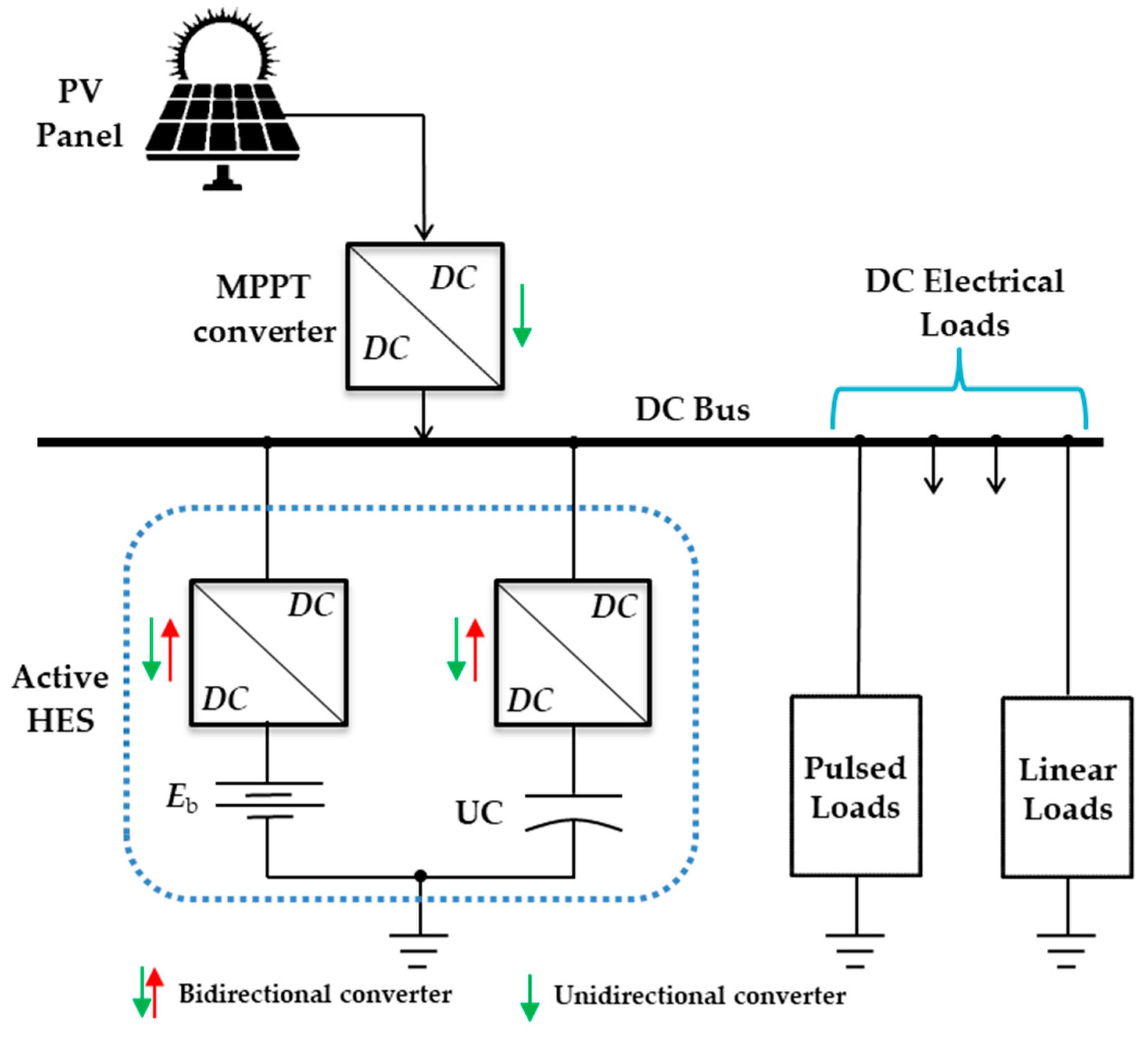
Figure 1. The structure of the suggested DC microgrid.
Fractalfract 09 00670 g001
Figure 2. The PV array model (a) characteristics, (b) equivalent circuit, (c) MPPT converter, and (d) battery converter.
Fractalfract 09 00670 g002
Figure 3. The supercapacitor’s model and converter.
Fractalfract 09 00670 g003
Figure 4. Structure of the conventional FBC for DC link voltage stabilization.
Fractalfract 09 00670 g004
Figure 5. The basic framework of the FOPI controller.
Fractalfract 09 00670 g005
Figure 6. Structure of the proposed FBC using the FOPI controller for DC bus voltage stabilization.
Fractalfract 09 00670 g006
Figure 7. The simulation disturbances for scenario #1 (a) sun insolation level, (b) load profile, (c) PV current, and (d) PV voltage.
Fractalfract 09 00670 g007aFractalfract 09 00670 g007b
Figure 8. The optimized FOPI and PI controllers’ responses using scenario #1 (a,b) bus voltage, (c,d) battery current, (e,f) state of charge, (g,h) ultracapacitor current, and (i,j) power.
Fractalfract 09 00670 g008aFractalfract 09 00670 g008b
Figure 9. The simulation disturbances for scenario #2 (a) sun insolation level, (b) load profile, (c) PV current (d) PV voltage.
Fractalfract 09 00670 g009aFractalfract 09 00670 g009b
Figure 10. The optimized FOPI and PI controllers’ responses using scenario #2 (a,b) bus voltage, (c,d) battery current, (e,f) state of charge, (g,h) ultracapacitor current, and (i,j) power.
Fractalfract 09 00670 g010aFractalfract 09 00670 g010b
Figure 11. The DC bus voltage response for scenario #1 (a) variation in LBF time constant, and (b) variation in (UC and its converter’s inductance).
Fractalfract 09 00670 g011aFractalfract 09 00670 g011b
Table 1. The controllers gains of the proposed FBC using the FOPI.
Control LoopParameterValue
Outer loop (common with BESS and UC)Kpv1.477
Kiv100
λv0.6
Inner loop (for BESS)Kpi0.043
Kii5
λi0.6
Inner loop (for UC)Kpi0.45
Kii5
λi0.5
Table 2. Comparison indictors of the proposed FBC using the FOPI and the PI controllers.
Scenario ControllerOvershoot (%)Settling Time (s)LSE of DC Bus VoltageImprovement vs. PI
1Pulsed load + PV variationPI~10%0.5 s1.0
1Pulsed load + PV variationOptimized FOPI~5%0.3 s0.280% lower LSE, 50% lower overshoot, 40% faster settling
2PV fault + dynamic loadPI~12%0.55 s1.2
2PV fault + dynamic loadOptimized FOPI~6%0.33 s0.2580% lower LSE, 50% lower overshoot, 40% faster settling
Table 3. A comparative analysis among recent control approaches.
Control MethodOvershootSettling TimeBattery StressComplexityNotes
PI/PIDHighSlowHighLowSimple, but weak under fast dynamics
SMCLowFastMediumMediumRobust but suffers chattering
MPCVery LowVery FastLowHighExcellent but computationally heavy
Droop/Filter-based [22]MediumMediumMediumLowWorks well for power sharing
Proposed FOPI (opt.) Low (~50% less)Fast (~40% faster)Low (reduced)MediumBalanced trade-off, optimized via GWO
Disclaimer/Publisher’s Note: The statements, opinions and data contained in all publications are solely those of the individual author(s) and contributor(s) and not of MDPI and/or the editor(s). MDPI and/or the editor(s) disclaim responsibility for any injury to people or property resulting from any ideas, methods, instructions or products referred to in the content.