Article

Phase-Based Fractional-Order Repetitive Control for Single-Phase Grid-Tied Inverters

by
Qiangsong Zhao
1,
Hao Dong
1,2,
Guohui Zhou
2 and
Yongqiang Ye
2,*
1
The School of Automation and Electrical Engineering, Zhongyuan University of Technology, Zhengzhou 450007, China
2
The College of Automation Engineering, Nanjing University of Aeronautics and Astronautics, Nanjing 211106, China
*
Author to whom correspondence should be addressed.
Fractal Fract. 2025, 9(10), 626; https://doi.org/10.3390/fractalfract9100626
Submission received: 1 September 2025 / Revised: 20 September 2025 / Accepted: 23 September 2025 / Published: 26 September 2025

Abstract

A novel fractional-order repetitive control based on phase angle information interpolation is proposed for single-phase LCL-type inverters in this paper. Conventional fractional-order repetitive control typically relies on inaccurate grid frequency information detected by a phase-locked loop or the frequency-locked loop, which may result in a potential degradation in harmonics suppression capability. To address this issue, phase information is investigated to implement the fractional order of the repetitive controller through the linear interpolation method. A major advantage of the proposed scheme lies in that it avoids explicit frequency calculation and reduces sensitivity to frequency estimation fluctuations compared with conventional fractional-order repetitive control, enhancing its frequency adaptability. The stability analysis and the design process for the proposed scheme based on a plug-in-type repetitive control are given. Experimental results support the efficacy and advantages of the proposed control strategy.

1. Introduction

In recent decades, distributed power generation systems (DPGSs), such as solar energy and wind energy, have experienced rapid growth and grid-tied inverters have emerged as an important interface that connects DPGSs to the power grid [1]. To minimize grid pollution, it is essential to maintain a minimal level of total harmonic distortion (THD) while ensuring a significantly high power factor. Therefore, the quality of the injected current is crucial.
Many current control schemes, such as proportional-integral (PI) control [2], resonant control [3], sliding mode control [4,5], and model predictive control [6], have been proposed for grid-tied inverters to deal with low-frequency harmonics stemming from nonlinear elements, including dead-time in pulse width modulation (PWM) inverters and nonlinear loads. Among these schemes, multi-resonant control for harmonic compensation can eliminate the selected harmonic components in the injected current [7]. However, it demands more design efforts and computational resources [8]. With a simple form, repetitive control (RC) allows for precise tracking of periodic signals with zero steady-state error or effective suppression of multiperiod disturbances due to its high gains at harmonic frequencies [9,10,11]. By introducing a phase-lead compensator, the phase lag caused by the plant can be effectively mitigated, making the controlled plant closer to the ideal characteristics required by RC, characterized by unity gain and zero phase shift within the specified bandwidth [12]. Moreover, with a plug-in repetitive controller, additional harmonics suppression performance can be achieved on the top of the base feedback controller [13]. In addition, a high-order repetitive control (HORC) [14] strategy has been explored for mitigating time-varying periodic disturbances.
For practical applications, RC is commonly employed in the discrete-time domain. The conventional RC (CRC), represented by z N / ( 1 z N ) , can achieve zero steady-state error only when f s / f g = N N , where f s refers to the sampling frequency, f g is the grid frequency of the inverter system, and N is the RC order. However, variations in grid frequency compromise the integer order of RC, thereby reducing open-loop gains at harmonic frequencies. To address this issue, two common approaches are employed: adjusting the sampling frequency and adopting frequency-based fractional-order filters. In particular, the time-varying sampling frequency method changes the sampling frequency online in response to fluctuations in grid frequency, thereby maintaining a consistent integer order for RC [15]. In [16], a multi-rate repetitive control is employed, precisely synchronizing the signal and control periods by adjusting the controller’s sampling time. In [17], a spatial RC, which utilizes the phase sampling technique to sample the grid voltage’s phase angle, has been proposed. Although it achieves a consistent number of samples in each cycle, it faces similar challenges as the previously mentioned method involving varying sampling rates. Ref. [18] implements a Gaussian process for the interpolation and extrapolation in the spatial RC to maintain a fixed sampling rate even though the scheme is a bit complex.
Moreover, the fractional-order RC (FORC) strategy is adopted to approximate the actual fractional order of RC. This method is especially pertinent when the grid frequency experiences variations, as delineated in several works. In [19], Escobar et al. pointed out that the order of RC could be a fraction when the grid frequency fluctuates and the sampling frequency is limited. They presented a solution to compensate for fractional delay with a finite impulse response (FIR) filter. In [20], a third-order FIR filter is used to approach the fractional order of RC for a programmable ac source. In [21], an infinite impulse-response (IIR) filter with a phase compensator can also achieve frequency adaptivity for grid-tied inverters. In [22], Valdez-Fernández et al. proposed a 6 h ± 1 repetitive scheme for a three-phase CHB seven-level converter in shunt APF applications, where a Farrow structure was introduced to compensate the variable fractional delay (VFD) induced by grid frequency deviations.
The grid frequency of the power grid from a phase-locked loop (PLL) or frequency-locked loop (FLL) is used to calculate the order of RC in the above-mentioned conventional FORC (CFORC). However, the detected frequency of the power grid may exhibit fluctuations in single-phase inverters. For instance, the output frequency of the PLL based on the second-order generalized integrator (SOGI) varies, even though these fluctuations can be mitigated to some extent with more advanced numerical techniques [23]. The voltage distortions at the point of common coupling (PCC) further exacerbate the situation. While more advanced PLL schemes are available to detect the grid frequency in three-phase inverters, single-phase inverters face greater challenges and increased complexity because of the limited availability of the grid voltage information. The undesired fluctuation of the estimated grid frequency leads to an imperfect order of RC, thus deteriorating the harmonics rejection performance of the CFORC schemes [24].
To tackle this challenge, the angle information from the PLL can be used to ascertain the grid frequency, and then deriving the order of RC. The contributions presented in this paper are as follows.
(1)
The output frequency of the second-order generalized integrator (SOGI)-based PLL naturally fluctuates, resulting in an inaccurate order of RC in a single-phase inverter, and then affecting the performance of RC. To solve this challenge, a novel phase-based fractional-order repetitive control (PFORC) scheme is developed in this paper.
(2)
Based on the linear interpolation method, the different weights are employed for the phase angles from PLL to determine the order of RC, which enhances the frequency adaptability of the PFORC scheme by mitigating the impact of fluctuations in the estimated grid frequency.
(3)
A detailed PFORC design procedure and the real-time comparative experimental validation on the single-phase LCL-type grid-tied inverters are presented, in which both performance and robustness are considered.

2. Conventional Frequency-Based Fractional-Order Repetitive Control

The structure of a plug-in RC system is shown in Figure 1. In Figure 1, C ( z ) is the base controller, P ( z ) is the plant. r ( z ) and y ( z ) are the reference and feedback signals, respectively. e ( z ) is the error and u R C ( z ) is the control output of RC, k R C is the gain of RC, Q ( z ) is a constant within ( 0 , 1 ) or a zero-phase low-pass filter in the form of d 1 z + d 0 + d 1 z 1 satisfying 2 d 1 + d 0 = 1 , aimed at boosting the system’s stability margin, and G f ( z ) is a compensation filter written as
G f ( z ) = G i ( z ) z m
where G i ( z ) is typically a low-pass filter, and z m is a phase lead compensator with m lead steps.
The transfer function of CRC is
G C R C ( z ) = u R C ( z ) e ( z ) = k R C z N Q ( z ) 1 z N Q ( z ) G f ( z ) .
When N N , G R C ( z ) has high gains at harmonic frequencies, and therefore, it can effectively attenuate harmonic signals.
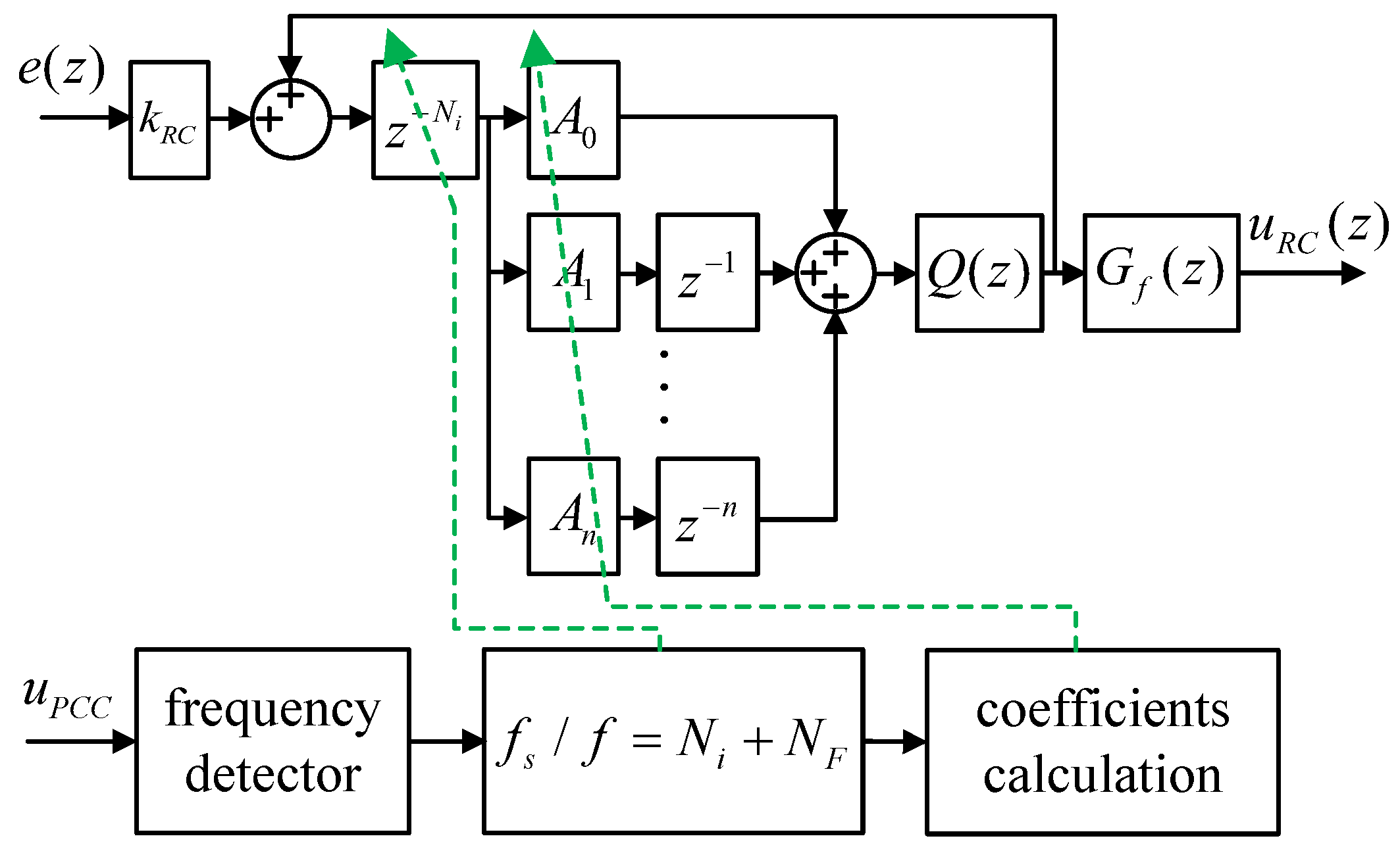
However, the open-loop gains at harmonic frequencies will decay when the fundamental frequency fluctuates, resulting in a deteriorated harmonics suppression performance of CRC. In [20], a CFORC is proposed to solve this problem. The order of RC (N), which is calculated by f s / f g , can be segmented into two components: an integer portion N i and a fractional portion N F , as shown in Figure 2. Then, an FIR filter is employed to approximate the fractional part z N F as follows:
z N F G F I R ( z ) = k = 0 n A k z k
where n is the order of FIR filter, k = 0 , 1 , . . . , n , and A k can be calculated by
A k = i = 0 , i k n N F i k i .
Typically, a larger n leads to less magnitude attenuation at low frequencies, which better approximates the unit gain. However, a high-order FIR fractional filter will increase the implementation complexity and change the closed-loop zeros of the system, and, the zeros may affect the dynamic response speed as well as the harmonic rejection ability. Therefore, in practice, the order of the adopted FIR fractional filter in the CFORC system is within the third order [24,25]. When a plug-in CFORC is employed, the stability conditions are of the same form as those of CRC [26]:
  • The closed-loop transfer function without RC, T ( z ) = C ( z ) P ( z ) ( 1 + C ( z ) P ( z ) ) , is stable;
  • | Q ( z ) G F I R ( z ) [ 1 k R C G f ( z ) T ( z ) ] | < 1 .
In practice, even if a narrow bandwidth of PLL or FLL is selected, the detected frequency from a typical SOGI-based PLL can fluctuate [27]. And then, the order of CFORC based on the frequency information will fluctuate, resulting in a degradation in harmonics suppression when the grid frequency remains fixed and a fixed order of RC is expected.

3. Proposed Phase-Based Fractional-Order Repetitive Control

3.1. Principle

The underlying principle of PFORC is to implement a repetitive controller based on phase angle information. In short, the order of RC can be determined by the number of interval samples of the same phase angle value. However, in practice, it is not possible to find the exact same phase angle in an adjacent fundamental wave period. Therefore, a linear interpolation method is needed for approximating the order of RC, with the interpolation coefficient calculated from the phase angle values. At time step k, it is appropriate to get a phase angle closest to the output current phase angle from the previous cycle. It is sufficient for the difference between these two phase angles to be less than 2 π f m i n / f s , where f m i n is the lower limit frequency of the varying grid frequency.
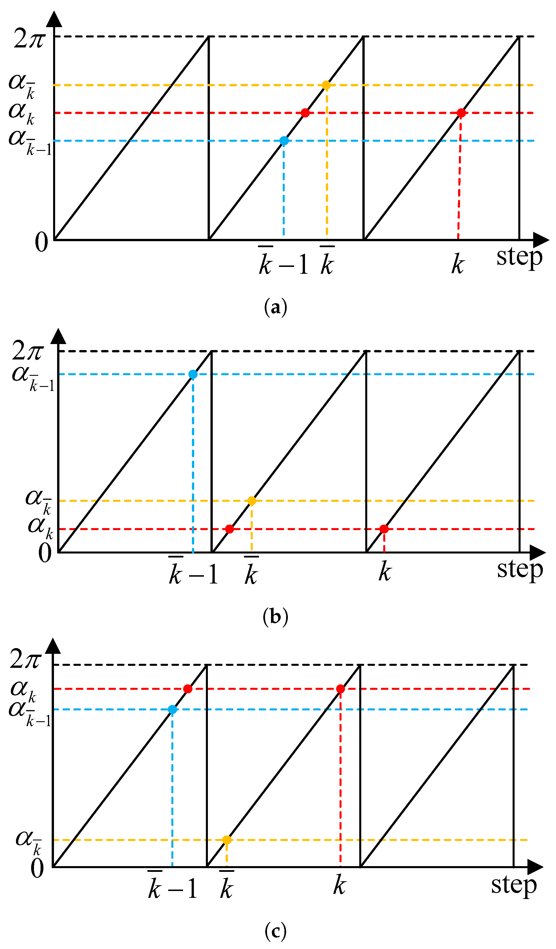
The order of RC can be categorized into two parts: the integer part N ( α ) and the fractional part N f . Notably, the order of RC can be calculated by identifying the two time steps k ¯ and k ¯ 1 , where k ¯ and k ¯ 1 are the sampling time steps of the last repetitive period in which corresponding the phase angles α k ¯ and α k ¯ 1 are closest to the current phase angle α k , which is typically the adjacent sampling point of the same phase angle N ( α ) of last repetitive period. α k lies between α k ¯ and α k ¯ 1 , as shown in Figure 3a. Therefore, the integer part can be formulated as
N ( α k ) = k k ¯ .
Based on the Lagrange interpolating method with the first order, the fractional part of the order can be derived from the weighting of phase angle differences between α k ¯ , α k , α k ¯ 1 . The linear interpolation of PFORC is shown in Figure 4a, where w 1 and w 2 represent the linear interpolation weights to approximate the ideal RC order. As a consequence, the delay line of RC can be written as
z N = z ( N ( α k ) + N f ) = z N ( α k ) · ( w 1 + w 2 z 1 ) .
In practice, the phase angle of the reference current is restricted within [ 0 , 2 π ) . Figure 4 illustrates the correlation between the phase angle of the phase around 2 π and the sampling time step in all three cases. In the case of Figure 3a, where α k ¯ 1 < α k < α k ¯ , the weights w 1 and w 2 can be expressed as follows:
w 1 = α k α k ¯ 1 α k ¯ α k ¯ 1 w 2 = 1 w 1 .
In the case of Figure 3b, where α k < α k ¯ < α k ¯ 1 , the weights w 1 and w 2 can be given as follows:
w 1 = α k + 2 π α k ¯ 1 α k ¯ + 2 π α k ¯ 1 w 2 = 1 w 1 .
In the case of Figure 3c, where α k ¯ < α k ¯ 1 < α k , the weights w 1 and w 2 can be given as follows:
w 1 = α k α k ¯ 1 α k ¯ + 2 π α k ¯ 1 w 2 = 1 w 1 .
As shown in Figure 5a shows, when a SOGI-based PLL is used for frequency detection, the order of CFORC fluctuates, leading to the fluctuation of weight A 1 , as illustrated in Figure 5b when n = 1 . The fluctuation in the calculated order of RC can deteriorate the performance of harmonics suppression when the grid frequency remains stable and a integral order of RC is expected. However, the fluctuation of the weights is mitigated, as depicted in Figure 5b, where w 2 remains almost constant at a steady state.
Remark 1.
The phase information of PLL can be used in the design of RC to circumvent the fluctuation problem in frequency detection. Compared to frequency-based CFORC, PFORC in the angular domain is more advantageous when the repetitive features of the reference or disturbance signals are reflected in the distribution of angular positions.

3.2. Implementation

At each sampling step, the updated phase angle is used to calculate the interpolation weights and stored in a memory buffer for subsequent period calculations. The buffer size for phase angle α should hold at least the maximum number of points per period, denoted as N max . Thus, N max = max [ N ( α k ) ] + 1 . For example, if the grid frequency varies in the range of 49 Hz to 51 Hz while the system samples and updates at a frequency of 20 kHz, then max [ N ( α k ) ] = f l o o r ( 20 , 000 / 49 ) = 408 , N max = max [ N ( α k ) ] + 1 = 409 .
The simplified diagram of PFORC is presented in Figure 4b, where ω 1 + ω 2 serves as an online mechanism for updating the RC order. Actually, PFORC exhibits an equivalent structure to CFORC during steady-state operations when the detected grid frequency remains constant, and the order of the fractional delay filter in CFORC is set to 1, (indicating the use of a linear interpolation polynomial). Thanks to the delay internal model, the structure of RC in Figure 4b can be implemented, as shown in Figure 6, where W ( z ) = w 1 + w 2 z 1 . In the transformed structure, z 1 Q ( z ) = d 1 + d 0 z 1 + d 1 z 2 is physically realizable.

3.3. Stability Conditions

In the implementation of PFORC, the phase angle of PLL is directly used for interpolation. An SOGI-based PLL is employed in this paper. High-order discretization of integrators leads to less ripple but more implementation efforts and computational burden [23]. Thus, integrators are discretized by feed-forward and backward Euler methods for simplicity. Phase from other types of PLL can also be used to calculate the weights w 1 and w 2 . It is noted that a narrow bandwidth of PLL is preferred for system stability [28]. Actually, considering that the maximum fluctuation rate of A is constrained [25], and the bandwidth of PLL is narrow, the online updating weights w 1 and w 2 only change slightly. So even though strict and conservative stability conditions have been proposed in [29], the stability conditions of the PFORC system are consistent with CFORC [20]:
➀ The system without RC is stable: T ( z ) is stable;
| Q ( z ) W ( z ) [ 1 k R C G f ( z ) T ( z ) ] | < 1 .

4. Application to a Single-Phase LCL-Type Grid-Tied Inverter

4.1. Modeling of the Single-Phase LCL-Type Grid-Tied Inverter

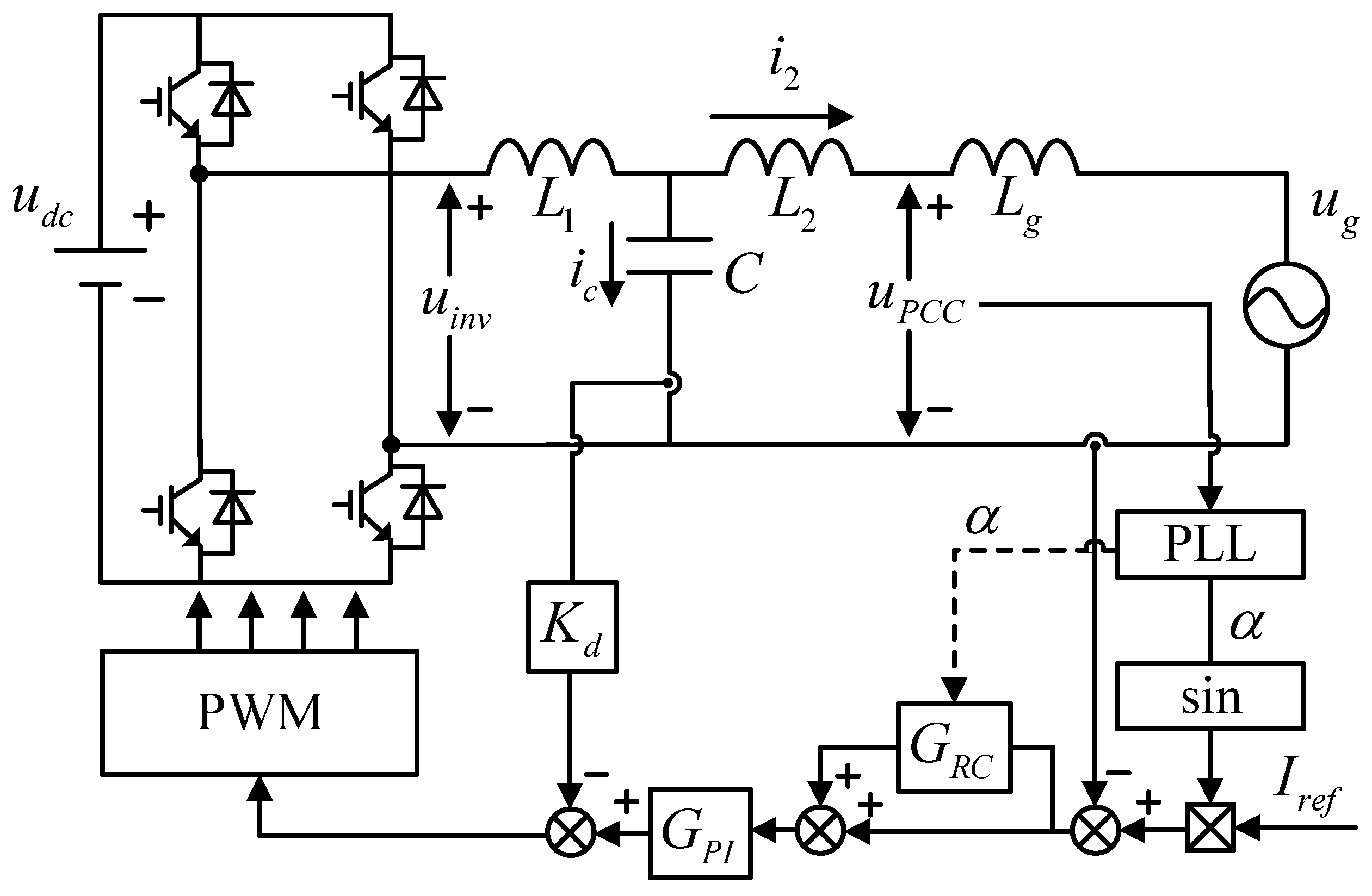
Figure 7 shows a single-phase L C L -type grid-tied inverter controlled by a plug-in RC, in which L 1 , L 2 , and C refer to the inverter-side filter inductor, grid-side filter inductor, and filter capacitor, respectively; I r e f is the amplitude of the reference current i r e f ; i 2 is the current of L 2 , respectively; i c is the capacitor current; u g is the grid voltage; u P C C is the voltage of the PCC; u d c is the dc bus voltage; L g is the grid inductor. A PLL is employed to synchronize i r e f with the phase angle of the grid. The phase angle from PLL α is fed into G R C for buffering. The capacitor current plays a role in actively damping the resonance peak, where K d is the active damping gain.
Figure 8 illustrates the system’s control diagram. The gain of the inverter bridge is represented by K p w m , and G h ( s ) symbolizes the zero-order-hold of PWM. This can be closely represented approximately as a time delay, specifically 0.5 T s , as suggested in [30]. Taking into account the digital control delay, the discrete transfer function of the open-loop gain without G R C is derived (see Appendix A) as follows:
H ( z ) = G P I ( z ) ω r ( L 1 + L 2 ) ( z 1 ) × ω r T s ( z 2 2 z cos ω r T s + 1 ) ( z 1 ) 2 sin ω r T s z ( z 2 2 z cos ω r T s + 1 ) + ( z 1 ) K d sin ω r T s ω r L 1
where ω r denotes the resonant angular frequency of the L C L filter, which is formalized as
ω r = L 1 + L 2 L 1 L 2 C .
The corresponding closed-loop transfer function with k RC = 0 is
T ( z ) = H ( z ) 1 + H ( z ) .

4.2. Controller Design

As depicted in Figure 8, G P I ( z ) is in the inner loop while G R C ( z ) is in the outer loop. Therefore, the PI controller, along with the active damping gain, should be tuned first considering system parameters. Then RC parameters can be determined based on the pre-tuned inner closed-loop.

4.2.1. PI Controller and Active Damping Gain

The base controller is used to ensure that the closed-loop function, T ( z ) , is stabilized. In this paper, a PI controller served as the base controller. The mathematical representation of a PI controller in discrete form is given by
G P I ( z ) = k p + k i T s z 1
where T s is the sampling period. Table 1 enumerates the system parameters utilized throughout this study. The selection of PI parameters and the active damping gain K d should ensure a flat magnitude frequency response of T ( z ) at the low frequency. Compared with unit gain, a flat closed-loop magnitude frequency response can reduce errors and be easily compensated by G f ( z ) (cf. the stability condition ➁ of PFORC). The selection of the system crossover frequency f c is actually affected by the resonant frequency f r . In instances where the resonant frequency f r falls under one-sixth of the sampling frequency, the loop gain crosses 180 at f r [31]. In this case, the crossover frequency f c must be set lower than the resonant frequency f r for system stability. The resonant frequency decreases as the grid inductance increases so that f r min = 1 2 π 1 / L 1 C 1.2 kHz . An f c of 650 Hz is selected, nearly half of f r min . Then k p is calculated by [2]:
k p 2 π f c ( L 1 + L 2 ) 20 .
Thus, k p = 20 is selected.
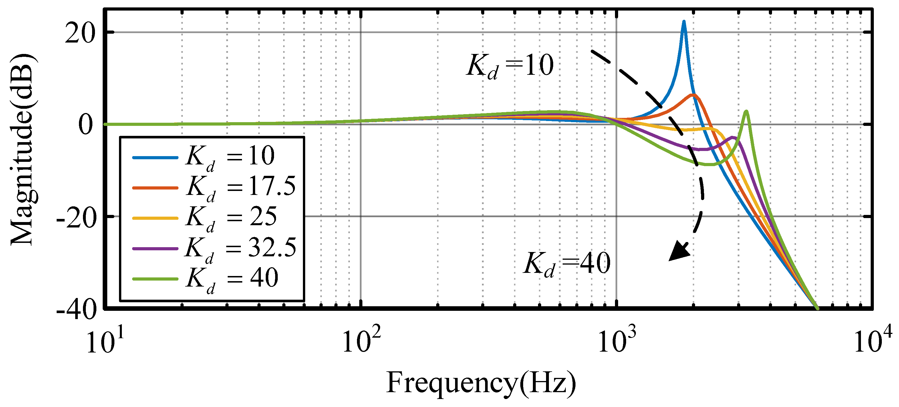
The integral term k i T s / ( z 1 ) is found to have a negligible impact on system stability [32], which allows for the subsequent determination of the active damping gain, K d . Let G P I = k p , the magnitude frequency responses of closed-loop transfer function T ( z ) with different damping coefficients K d are illustrated in Figure 9. It can be seen that when K d = 25 , T ( z ) exhibits the smoothest magnitude frequency response, which means T ( z ) is nearly a unit gain at low frequency and provides a greater stability margin for RC. Hence, K d = 25 is selected. As k i increases, the gain of H ( z ) at the low frequency rises while the phase margin of H ( z ) decreases. To balance between phase margin and dynamic response, k i = 15,000 is selected. The final phase margin and the gain margin of H ( z ) are 50 and 4.7 dB, respectively.

4.2.2. Q ( z )

Q ( z ) is to ensure a safe margin with respect to stability condition ➁. A low-pass filter with zero-phase characteristics significantly enhances the stability margin in the high-frequency range. Hence, Q ( z ) = 0.05 z + 0.9 + 0.05 z 1 is chosen to provide enough gain in the low-frequency range.

4.2.3. G f ( z )

G f ( z ) functions as a compensation filter and approximates the inverse of T ( z ) at low frequencies. As Equation (1) shows that the design of G f ( z ) can be categorized into two parts, G i ( z ) for high-frequency attenuation and z m for phase compensation. For simplicity, a Butterworth low-pass filter with a second-order configuration is employed for its flat frequency response in the passband. The main harmonics are below the 20th harmonic, so a cutoff frequency of 1000 Hz is selected for the filter. G i ( s ) is then discretized with bi-linear transformation:
G i ( z ) = 0.01979 z 2 + 0.03958 z + 0.01979 z 2 1.565 z + 0.6437 .
After the filter G i ( z ) has been designed, the lead step m should be selected to compensate for the phase lag of the system at the low frequency. Figure 10 displays the phase–frequency responses of T ( z ) G i ( z ) z m with different m. As shown in Figure 10, increasing m enhances the maximum phase lead but narrows the effective bandwidth. Specifically, m = 8 provides only limited phase improvement, whereas m = 13 yields a larger phase lead at the expense of a significantly narrower bandwidth. The phase–frequency curves indicate that m = 11 achieves a phase of T ( z ) G f ( z ) closest to 0 . Thus, m = 11 is selected in conjunction with the designed G i ( z ) to compensate T ( z ) and approximate unit gain in the low-frequency range.

4.2.4. k RC

It is revealed that the larger the value of k R C , the better the steady-state response and dynamic performance. But it can also deteriorate the stability of the system. Let
M = max ( | 1 k R C T ( z ) G i ( z ) z m | ) .
If 20 lg ( M ) < 0 dB, system stability is ensured. System stability is assessed while varying L g up to 0.1 PU, corresponding to a short-circuit ratio of about 10 [32], and
L g max = u g 2 2 π f g 10 P o 7.7 mH .
Thus, 8 mH is selected as the upper bound of L g . Figure 11 shows the distribution of 20 lg ( M ) concerning k R C and L g . As grid inductance L g increases, the stability region for k R C decreases. When L g = 8 mH, the stability region for k R C is about ( 0 , 1.5 ) . Therefore, k R C = 1 is selected as a compromise between dynamic performance and system stability.

5. Experimental Verification

To substantiate the validity of the proposed scheme, a 2 kW single-phase L C L -type grid-tied inverter has been established in the laboratory. The experimental setup is depicted in Figure 12. A TMS320F28335 digital signal controller (Texas Instruments, Dallas, TX, USA) is employed in the setup and the PM50RLA060 intelligent power module (Mitsubishi Electric, Tokyo, Japan) is adopted. A Chroma 62100H-1000 programmable DC power supply (Chroma ATE Inc., Taoyuan, Taiwan) provides the necessary DC bus voltage. System parameters are listed in Table 1. It is worth mentioning that a double-sampling double-load mode was employed to reduce the time delay [33]. The PI controller, RCs and PLL all update twice within a switching period.

5.1. Steady State Response

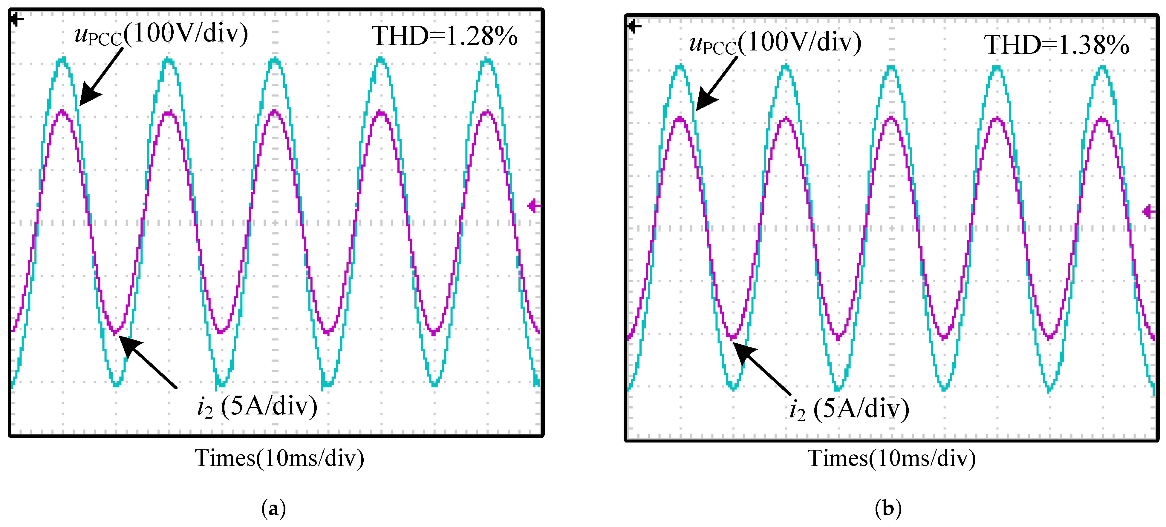
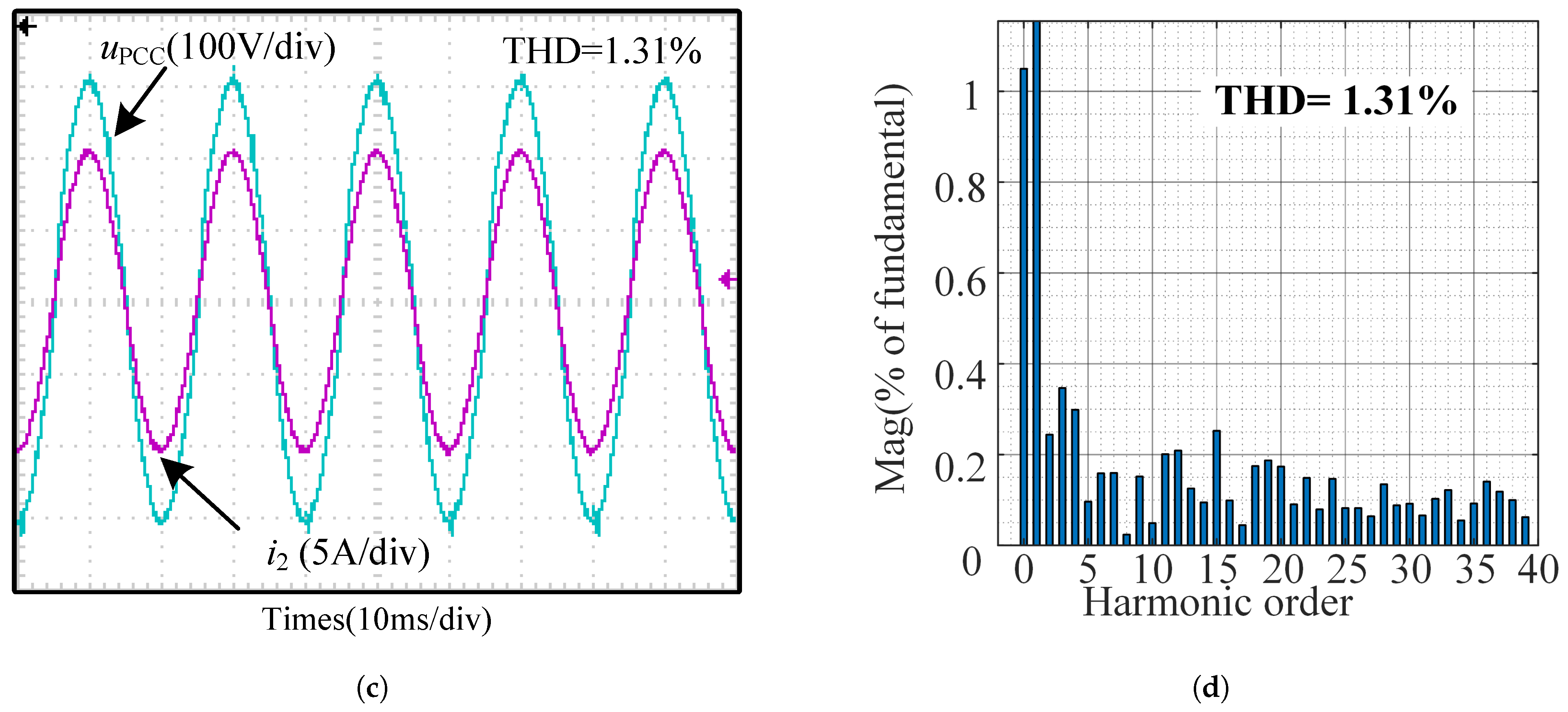
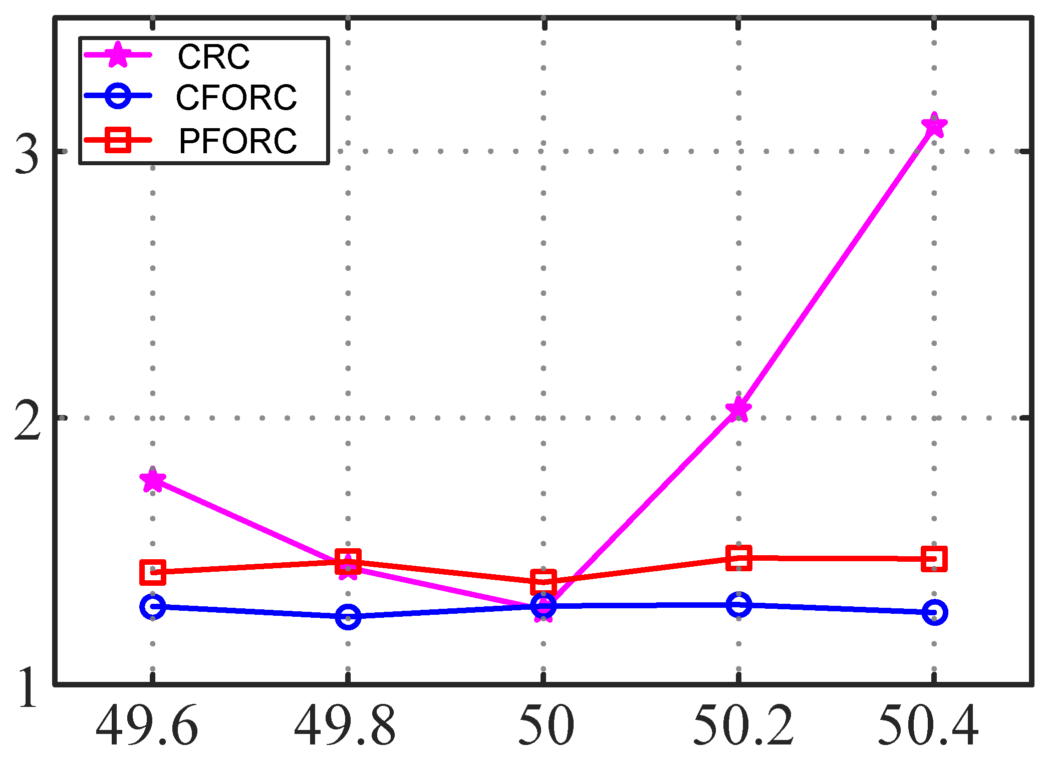
The reference current amplitude is 10 A, which is synchronized to the grid voltage via an SOGI-based PLL. When f g is 50 Hz, the waveforms of the injected current i 2 with varying RCs are shown in Figure 13. The THD results of i 2 under CRC, CFORC and PFORC are almost identical, measuring 1.28%, 1.38% and 1.31%, respectively. The THD results under different RCs and grid frequencies are summarized in Figure 14. When f g is set to 49.6 Hz, CRC still maintains the order of RC as N = 400, and the THD of i 2 rises to 1.77%. However, the THDs of i 2 with CFORC and PFORC are 1.42% and 1.29%, respectively. when f g is set to 50.4 Hz, CRC achieves a THD of 3.09%, while CFORC and PFORC achieve 1.47% and 1.27%, respectively.
Obviously, when the grid frequency varies, the THD results of CRC deteriorate while the THD results of CFORC and PFORC remain stable thanks to their frequency adaptivity. Moreover, PFORC achieves lower THD results than CFORC, which validates PFORC’s adaptivity to frequency fluctuations.

5.2. Transient Response

The injected current’s response regarding the current amplitude step change is illustrated to test the proposed approach’s transient response. Figure 15 presents the response of injected current i 2 and u P C C while the reference current steps up and down at the peak of the sine wave, which corresponds to a phase angle of π 2 . The step change in the reference current at the peak position causes glitches of i 2 starting from the same position in the following periods. However, the steady state is reached within 5 cycles. Therefore, the proposed approach can remain stable even with a step change in the reference current.
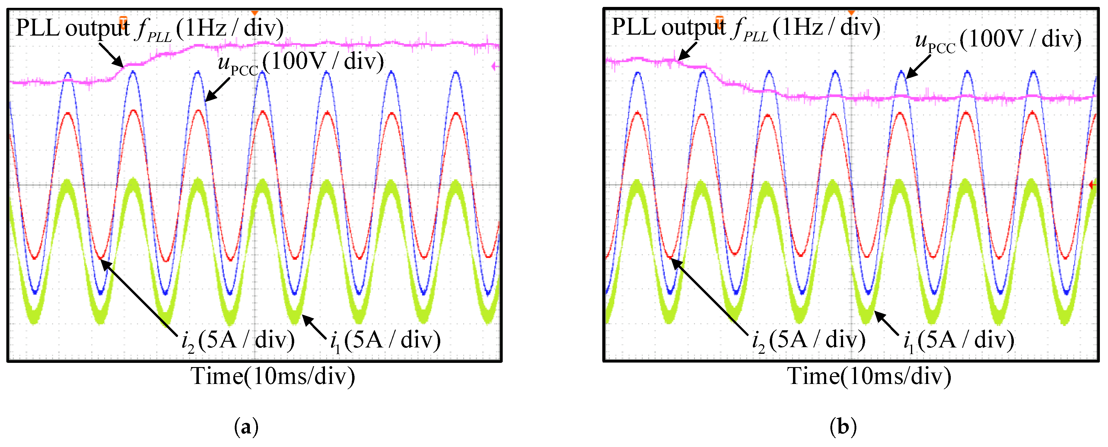
To substantiate the adaptability of PFORC to different frequencies, a programmable power grid simulator Chroma 61512 (Chroma ATE Inc., Taoyuan, Taiwan) is employed to simulate the grid. The transient responses of the system under grid frequency step changes are shown in Figure 16. The detection of grid frequency step changes takes approximately 30 ms. With a fluctuating PLL output frequency f P L L , PFORC maintains a sinusoidal injected current i 2 .
The current tracking error with respect to the PLL output frequency under CRC, FORC, and PFORC control schemes is shown in Figure 17. Before f P L L step change happens, PFORC has the smallest current tracking error. After the step change, the current tracking errors of PFORC rises to almost the same amplitude of FORC and CRC but soon converges after about 3 periods (0.06 s). It is concluded that during grid frequency change, the current tracking error of PFORC, FORC and CRC have almost the same amplitude. However, PFORC can achieve better tracking accuracy under steady-state conditions.
As shown in Figure 17, accurate frequency information is critical for the performance of the CRC and FORC. Frequency measurement errors can degrade the robustness of these controllers under frequency variations, thereby reducing harmonics suppression and increasing current deviations. The proposed PFORC achieves fractional delay by interpolating PLL phase-angle samples. Compared with the CRC and FORC, this approach is less sensitive to frequency estimation errors, allowing it to maintain small current deviations even under frequency fluctuations.

5.3. Robustness Experiments

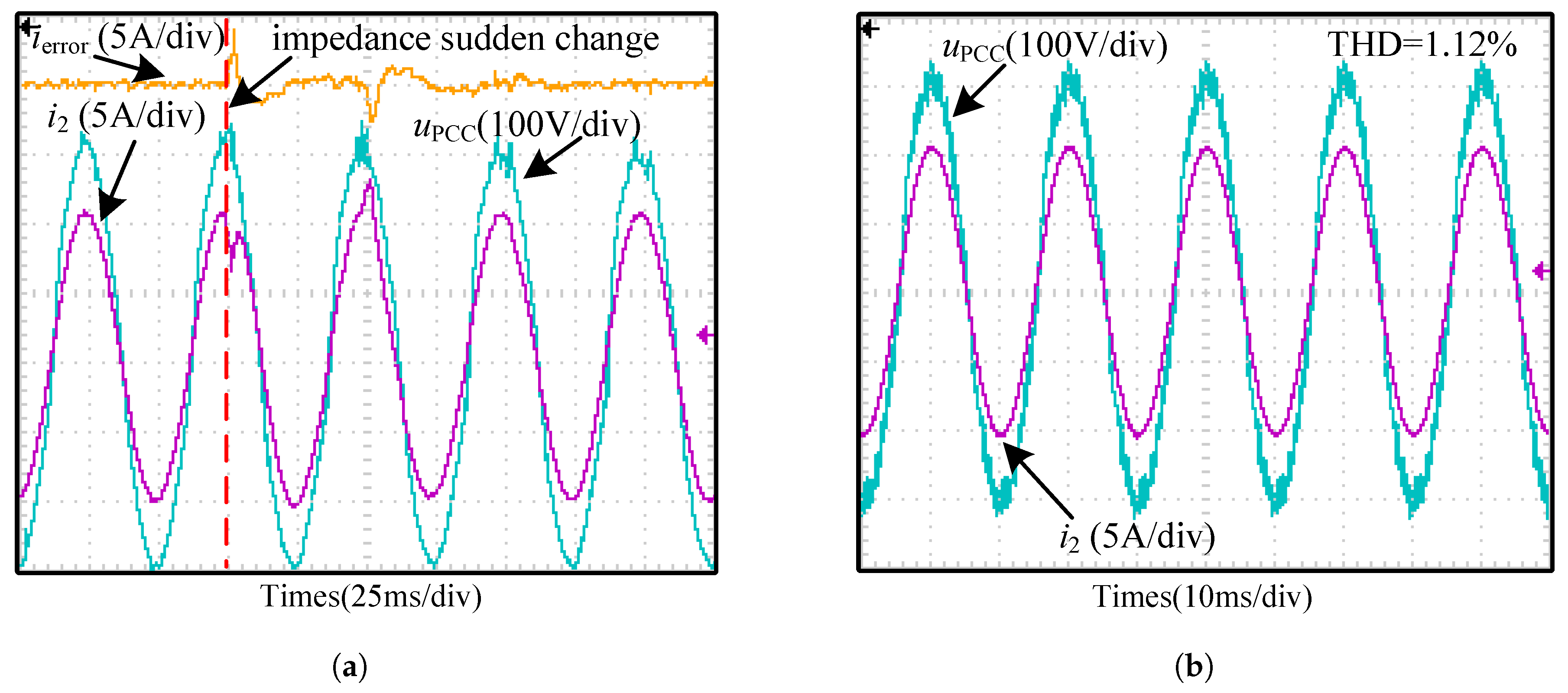
The inverter works when the grid impedance sudden changes to test the robustness of the proposed scheme under the weak grid. Figure 18a shows the waveform of i 2 and u P C C while the grid impedance suddenly changes to an inductor in parallel with a resistor. In this case, a 3.8 mH inductor is selected to simulate the grid inductance L g . A resistor of 18 Ω and a breaker are in parallel with L g . The breaker is initially closed-up, short-circuiting L g and the resistor. The red dashed line in Figure 18a indicates the moment when the breaker is turned off, leading to the sudden change of the grid impedance. It can be seen from Figure 18a that the distortion of i 2 recovers within two periods. Thus, the proposed PFORC scheme demonstrates robust resilience to abrupt changes in grid impedance. To further validate the designed control parameters against grid inductance variation, an 8 mH inductor is used to simulate the grid inductance L g . As Figure 18b shows, the system remains stable and the THD of i 2 is 1.12%. That is, the proposed scheme with designed system parameters performs well under grid inductance variation.

6. Conclusions

In this paper, a straightforward and effective PFORC based on the phase information is proposed to achieve frequency adaptation, which overcomes the problem of frequency fluctuations captured from the PLL faced by CFORC. The linear interpolation method that leverages the difference of phase angle serves to enhance the frequency adaptation capability of RC. An extra memory buffer for phase angles is needed for the practical implementation of this scheme. Insensitive to detected frequency fluctuations, PFORC demonstrates superior harmonics suppression performance at the cost of extra memory buffer usage for phase angle. Furthermore, the proposed scheme exhibits enhanced tracking accuracy in a steady state. Comparative experimental results demonstrate the proposed scheme’s benefits and the robustness of the designed parameters in the face of grid inductance fluctuations.

Author Contributions

Conceptualization, Q.Z., H.D., and Y.Y.; formal analvsis, H.D.; methodology, H.D.; software, H.D.; validation, H.D.; writing—original draft, H.D.; writing—review & editing, H.D. and G.Z.; supervision, Y.Y. All authors have read and agreed to the published version of the manuscript.

Funding

This work was supported in part by the National Natural Science Foundation of China under Grants 62441315 and 62433020, and in part by the Natural Science Foundation of Henan under Grant 252300421299, and in part by the Key Research and Development Projects in Henan Province under Grants 242102240115, and in part by the 2023 outstanding scientific and technological innovation talent support program of Zhongyuan University of Technology under Grant K2023YXRC03.

Data Availability Statement

All data supporting the findings of this study are contained within the article. No additional data are available.

Conflicts of Interest

The authors declare that they have no known competing financial interests or personal relationships that could have appeared to influence the work reported in this paper.

Appendix A

The derivation of Equation (10) proceeds as follows. First, the transfer function from the inverter output voltage u i n v to the inverter-side current i 1 can be expressed as
G 1 ( s ) = i 1 ( s ) u i n v ( s ) = 1 L 1 + L 2 · 1 s + L 2 L 1 ( L 1 + L 2 ) · s s 2 + ω r 2
The transfer function is subsequently discretized via a zero-order hold (ZOH) and can be written as
G 1 ( z ) = T s ( L 1 + L 2 ) ( z 1 ) + L 2 L 1 ( L 1 + L 2 ) · z 1 z 2 2 z cos ( ω r T s ) + 1 · sin ( ω r T s ) ω r = 1 L 1 + L 2 · T s ( z 2 2 z cos ( ω r T s ) + 1 ) + L 2 L 1 ( z 1 ) 2 sin ( ω r T s ) ω r ( z 1 ) ( z 2 2 z cos ( ω r T s ) + 1 ) .
There exists a small equivalent phase delay in the inverter during modulation and driving. After linearization, this delay manifests in the discrete domain as an additional term in the system denominator, proportional to ( z 1 ). This additional term can be parameterized
α = K d sin ( ω r T s ) ω r L 1
The delay block M ( z ) represents the equivalent time delay in a discrete-time system caused by sampling, holding, or signal transmission. Its expression can be given by
M ( z ) = 1 K p w m · z 1 1 + α · z 1 z = 1 K p w m · 1 z + α ( z 1 ) .
Based on the above analysis and Figure 8, the discrete transfer function of the open-loop gain without G R C is as follows:
H ( z ) = G P I ( z ) M ( z ) G 1 ( z ) = G P I ( z ) ω r ( L 1 + L 2 ) ( z 1 ) × ω r T s ( z 2 2 z cos ω r T s + 1 ) ( z 1 ) 2 sin ω r T s z ( z 2 2 z cos ω r T s + 1 ) + ( z 1 ) K d sin ω r T s ω r L 1

References

  1. Chen, J.; Zhang, L.; Li, H.; Zhang, X. Static and dynamic event-triggered mechanisms for distributed sec-ondary control of inverters in low-voltage islanded microgrids. IEEE Trans. Cybern. 2022, 52, 6925–6938. [Google Scholar] [CrossRef] [PubMed]
  2. Wang, J.; Wang, F.; Wang, G.; Li, S.; Yu, L. Generalized proportional integral observer based robust finite control set predictive current control for induction motor systems with time-varying disturbances. IEEE Trans. Ind. Inform. 2018, 14, 4159–4168. [Google Scholar] [CrossRef]
  3. Shubhra, S.; Singh, B. Three-phase grid-interactive solar PV-battery microgrid control based on normalized gradient adaptive regularization factor neural filter. IEEE Trans. Ind. Inform. 2020, 16, 2301–2314. [Google Scholar] [CrossRef]
  4. Kurniawan, E.; Burrohman, A.M.; Purwowibowo, P.; Wijonarko, S.; Maftukhah, T.; Prakosa, J.A.; Rustandi, D.; Pratiwi, E.B.; Az-Zukhruf, A. Discrete-time design of fractional delay-based repetitive controller with sliding mode approach for uncertain linear systems with multiple periodic signals. Fractal Fract. 2025, 9, 41. [Google Scholar] [CrossRef]
  5. Chigane, K.; Ouassaid, M. Experimental assessment of integral-type terminal sliding mode control designed for a single-phase grid-interlinked PV system. Control Eng. Pract. 2024, 147, 105903. [Google Scholar] [CrossRef]
  6. Liu, E.; Han, Y.; Zalhaf, A.S.; Yang, P.; Wang, C. Performance evaluation of isolated three-phase voltage source inverter with LC filter adopting different MPC methods under various types of load. Control Eng. Pract. 2023, 135, 105520. [Google Scholar]
  7. Zhao, Q.; Zhang, H.; Xia, Y.; Chen, Q.; Ye, Y. Equivalence relation analysis and design of repetitive con-trollers and multiple quasi-resonant controllers for single-phase inverters. IEEE J. Emerg. Sel. Top. Power Electron. 2025, 13, 3338–3349. [Google Scholar] [CrossRef]
  8. Liang, F.; Lee, H.-J.; Zhang, H. Fractional-order phase lead compensation multirate repetitive control for grid-tied inverters. Fractal Fractals 2023, 7, 848. [Google Scholar] [CrossRef]
  9. Huang, P.; Li, Z.; Zhou, M.; Kan, Z. Divergent component of motion planning and adaptive repetitive control for wearable walking exoskeletons. IEEE Trans. Cybern. 2024, 54, 2244–2256. [Google Scholar] [CrossRef] [PubMed]
  10. Pandove, G.; Singh, M. Robust repetitive control design for a three-phase four-wire shunt active power filter. IEEE Trans. Ind. Informat. 2019, 15, 2810–2818. [Google Scholar] [CrossRef]
  11. Zhao, Q.; Wang, Q.; Zhang, H.; Xia, Y.; Ye, Y. A novel RC-ESO-ADRC for harmonics suppression and robustness improvement of grid-tied inverters in a weak and distorted grid. IEEE Trans. Power Electron. 2025, 40, 12581–12593. [Google Scholar] [CrossRef]
  12. Zhang, B.; Wang, D.; Zhou, K.; Wang, Y. Linear phase lead compensation repetitive control of a CVCF PWM inverter. IEEE Trans. Ind. Electron. 2008, 55, 1595–1602. [Google Scholar] [CrossRef]
  13. Zhao, Q.; Zhou, G.; Xia, Y.; Zhu, Y.; Yu, D.; Zhang, H. Feedforward dual-mode repetitive control for sin-gle-phase V2G inverters in residential grids. IEEE Trans. Transp. Electrific. 2025, 11, 10927–10937. [Google Scholar] [CrossRef]
  14. Kurniawan, E.; Wang, H.; Septanto, H.; Adinanta, H.; Suryadi, S.; Pratomo, H.; Hanto, D. Design and analysis of higher-order repetitive sliding mode controller for uncertain linear systems with time-varying periodic disturbances. Trans. Inst. Meas. Control. 2023, 45, 2219–2234. [Google Scholar] [CrossRef]
  15. Herrán, M.A.; Fischer, J.R.; González, S.A.; Judewicz, M.G.; Carugati, I.; Carrica, D.O. Repetitive control with adaptive sampling frequency for wind power generation systems. IEEE J. Emerg. Sel. Top. Power Electron. 2014, 2, 58–69. [Google Scholar] [CrossRef]
  16. Cao, Z.; Ledwich, G. Adaptive repetitive control to track variable periodic signals with fixed sampling rate. IEEE/ASME Trans. Mechatron. 2002, 7, 378–384. [Google Scholar]
  17. Kolluri, S.; Gorla, N.B.Y.; Sapkota, R.; Panda, S.K. A new control architecture with spatial comb filter and spatial repetitive controller for circulating current harmonics elimination in a droop-regulated modular multilevel converter for wind farm application. IEEE Trans. Power Electron. 2019, 34, 10509–10523. [Google Scholar] [CrossRef]
  18. Mooren, N.; Witvoet, G.; Oomen, T. Gaussian process repetitive control with application to an industrial substrate carrier system with spatial disturbances. IEEE Trans. Control Syst. Technol. 2023, 31, 344–358. [Google Scholar] [CrossRef]
  19. Escobar, G.; Mattavelli, P.; Hernandez-Gomez, M.; Martinez-Rodriguez, P.R. Filters with linear-phase properties for repetitive feedback. IEEE Trans. Ind. Electron. 2014, 61, 405–413. [Google Scholar] [CrossRef]
  20. Chen, Y.; Zhou, K.; Tang, C.; Shu, Y.; Yang, Y. Fractional-order multiperiodic odd-harmonic repetitive control of programmable AC power sources. IEEE Trans. Power Electron. 2022, 37, 7751–7758. [Google Scholar] [CrossRef]
  21. Liu, P.; Wang, C.; Zhang, Y.; Liang, Y.; Cui, Y.; Fang, J. Frequency adaptive repetitive control of new energy grid-connected inverter based on improved IIR. IEEE Trans. Power Electron. 2023, 38, 9539–9551. [Google Scholar] [CrossRef]
  22. Valdez-Fernández, A.A.; Escobar, G.; Catzin-Contreras, G.A.; Hernández-Ruíz, M.E.; Morales-Caporal, R. A 6h±1 repetitive scheme for the three-phase CHB seven-level converter used in an APF application. IEEE J. Emerg. Sel. Top. Power Electron. 2024, 12, 1641–1653. [Google Scholar] [CrossRef]
  23. Ciobotaru, M.; Teodorescu, R.; Blaabjerg, F. A new single-phase PLL structure based on second order generalized integrator. In Proceedings of the 2006 37th IEEE Power Electronics Specialists Conference, Jeju, Republic of Korea, 18–22 June 2006; pp. 1–6. [Google Scholar]
  24. Yang, Y.; Zhou, K.; Blaabjerg, F. Enhancing the frequency adaptability of periodic current controllers with a fixed sampling rate for grid-connected power converters. IEEE Trans. Power Electron. 2016, 31, 7273–7285. [Google Scholar] [CrossRef]
  25. Zou, Z.-X.; Zhou, K.; Wang, Z.; Cheng, M. Frequency-adaptive fractional-order repetitive control of shunt active power filters. IEEE Trans. Ind. Electron. 2015, 62, 1659–1668. [Google Scholar] [CrossRef]
  26. Zhou, K.; Wang, D. Digital repetitive learning controller for three-phase CVCF PWM inverter. IEEE Trans. Ind. Electron. 2001, 48, 820–830. [Google Scholar] [CrossRef]
  27. Xu, J.; Qian, H.; Hu, Y.; Bian, S.; Xie, S. Overview of SOGI-based single-phase phase-locked loops for grid synchronization under complex grid conditions. IEEE Access 2021, 9, 39275–39291. [Google Scholar] [CrossRef]
  28. Hu, B.; Nian, H.; Li, M.; Liao, Y.; Yang, J.; Tong, H. Impedance characteristic analysis and stability improvement method for DFIG system within PLL bandwidth based on different reference frames. IEEE Trans. Ind. Electron. 2023, 70, 532–543. [Google Scholar] [CrossRef]
  29. Merry, R.; Kessels, D.; Heemels, W.; Molengraft, M.v.; Steinbuch, M. Delay-varying repetitive control with application to a walking piezo actuator. Automatica 2011, 47, 1737–1743. [Google Scholar] [CrossRef]
  30. Chen, S.; Zhao, Q.; Ye, Y.; Qu, B. Using IIR filter in fractional order phase lead compensation PIMR-RC for grid-tied inverters. IEEE Trans. Ind. Electron. 2023, 70, 9399–9409. [Google Scholar] [CrossRef]
  31. Pan, D.; Ruan, X.; Bao, C.; Li, W.; Wang, X. Optimized controller design for LCL-type grid-connected inverter to achieve high robustness against grid-impedance variation. IEEE Trans. Ind. Electron. 2015, 62, 1537–1547. [Google Scholar] [CrossRef]
  32. Liserre, M.; Teodorescu, R.; Blaabjerg, F. Stability of photovoltaic and wind turbine grid-connected inverters for a large set of grid impedance values. IEEE Trans. Power Electron. 2006, 21, 263–272. [Google Scholar] [CrossRef]
  33. Zhou, L.; Zhou, X.; Chen, Y.; Lv, Z.; He, Z.; Wu, W.; Yang, L.; Yan, K.; Luo, A.; Guerrero, J.M. Invert-er-current-feedback resonance-suppression method for LCL-type DG system to reduce resonance-frequency offset and grid-inductance effect. IEEE Trans. Ind. Electron. 2018, 65, 7036–7048. [Google Scholar] [CrossRef]
Figure 1. Block diagram of the plug-in RC system.
Fractalfract 09 00626 g001
Figure 2. Block diagram of CFORC.
Fractalfract 09 00626 g002
Figure 3. Phase angle versus sampling time step: (a) α k ¯ 1 < α k < α k ¯ , (b) α k < α k ¯ < α k ¯ 1 , and (c) α k ¯ < α k ¯ 1 < α k .
Fractalfract 09 00626 g003
Figure 4. Diagram of PFORC: (a) PFORC with linear interpolation, (b) simplified diagram.
Fractalfract 09 00626 g004aFractalfract 09 00626 g004b
Figure 5. Simulation results under 49 Hz sinusoidal grid voltage at a steady state: (a) order N of CFORC, (b) value of weight coefficients: A 1 and w 2 .
Fractalfract 09 00626 g005aFractalfract 09 00626 g005b
Figure 6. Structure for implementation.
Fractalfract 09 00626 g006
Figure 7. Plug-in RC of L C L -type single-phase grid-tied inverter.
Fractalfract 09 00626 g007
Figure 8. Control diagram of the single-phase L C L -type grid-tied inverter with grid inductance.
Fractalfract 09 00626 g008
Figure 9. Magnitude frequency responses of T ( z ) with different K d .
Fractalfract 09 00626 g009
Figure 10. Phase frequency responses of T ( z ) G f ( z ) with different m.
Fractalfract 09 00626 g010
Figure 11. Amplitude of M versus 0 dB plane with different k R C and L g .
Fractalfract 09 00626 g011
Figure 12. Grid-tied inverter hardware built for experiments.
Fractalfract 09 00626 g012
Figure 13. Experimental results (continued): (a) CRC, (b) CFORC, (c) PFORC, (d) the spectrum analysis of grid current of the proposed PFORC.
Fractalfract 09 00626 g013aFractalfract 09 00626 g013b
Figure 14. THD of i 2 of different schemes under grid frequency variation.
Fractalfract 09 00626 g014
Figure 15. Experimental transient waveform of reference step change. (a) Reference steps up. (b) Reference steps down.
Fractalfract 09 00626 g015
Figure 16. Responses to step changes in grid frequency. (a) From 49.5 Hz to 50.5 Hz. (b) From 50.5 Hz to 49.5 Hz.
Fractalfract 09 00626 g016
Figure 17. Current tracking error with stepping grid frequency (49.5 Hz to 50.5 Hz). (a) CRC. (b) FORC. (c) PFORC.
Fractalfract 09 00626 g017
Figure 18. Robustness experiments (a) Transient waveform of u P C C and i 2 under sudden change of grid impedance. (b) Injected curent i 2 under PFORC with f g = 50 Hz, L g = 8 mH.
Fractalfract 09 00626 g018
Table 1. System parameters.
SymbolQuantityNominal Value
u d c DC-link voltage380 V
u g Grid voltage (RMS)220 V
P o Output power2 kW
C d c DC bus capacitor1360 uF
L 1 Inverter side inductance2.9 mH
CFilter Capacitor6 µF
L 2 Grid side inductance2 mH
f s w Switching frequency10 kHz
f s Sampling frequency20 kHz
f b w PLL bandwidth15 Hz
ζ P L L PLL damping ratio0.707
K P W M PWM Gain1
Disclaimer/Publisher’s Note: The statements, opinions and data contained in all publications are solely those of the individual author(s) and contributor(s) and not of MDPI and/or the editor(s). MDPI and/or the editor(s) disclaim responsibility for any injury to people or property resulting from any ideas, methods, instructions or products referred to in the content.