Abstract
In this paper, a novel robust finite-time control scheme is specifically designed for a class of under-actuated nonlinear systems. The proposed scheme integrates a reaching phase-free integral backstepping method with an integral terminal fractional-order sliding mode to ensure finite-time stability at the desired equilibria. The core of the algorithm is built around proportional-integral-based nonlinear virtual control laws that are systematically designed in a backstepping manner. A fractional-order integral terminal sliding mode is introduced in the final step of the design, enhancing the robustness of the overall system. The robust nonlinear control algorithm developed in this study guarantees zero steady-state errors at each step while also providing robustness against matched uncertain disturbances. The stability of the control scheme at each step is rigorously proven using the Lyapunov candidate function to ensure theoretical soundness. To demonstrate the practicality and benefits of the proposed control strategy, simulation results are provided for two systems: a cart–pendulum system and quadcopter UAV. These simulations illustrate the effectiveness of the proposed control scheme in real-world scenarios. Additionally, the results are compared with those from the standard literature to highlight the superior performance and appealing nature of the proposed approach for underactuated nonlinear systems. This comparison underscores the advantages of the proposed method in terms of achieving robust and stable control in complex systems.
1. Introduction
The field of control theory has witnessed significant advancements in recent years, particularly in the realm of nonlinear control techniques. This progress has been spurred by the increasing demand for effective control strategies to tackle the complexities of modern systems, particularly under-actuated nonlinear systems (UNSs). UNSs are characterized by fewer dimensions in the space spanned by stabilizing inputs compared with configuration variables, which makes their control design more challenging and intriguing for researchers [,]. UNSs find extensive applications in various domains such as robotics, unmanned aerial vehicles (UAVs), underwater vehicles, surface vessels, satellite systems, and locomotives [,,,,]. In these applications, precise control is crucial for ensuring stability, performance, and safety. For instance, UNSs are often used in robotic arms and mobile robots, where efficient and reliable control is necessary for tasks such as manipulation and navigation. In UAVs, robust control strategies are vital for maintaining stability and achieving desired flight trajectories under varying environmental conditions.
The design of robust control algorithms for UNSs has emerged as a focal point for researchers driven by the pressing need to achieve the desired performance while ensuring stability in real-world applications. The inherent advantages offered by UNSs, such as reduced energy consumption, cost, weight, and low component failure rates, further underscore the importance of developing effective control methodologies tailored to their unique characteristics. However, controlling UNSs presents significant challenges owing to the presence of nonintegrable constraints. These constraints complicate the implementation of smooth control approaches, necessitating the development of innovative strategies that can handle the nonlinearities and under-actuated nature of these systems [,]. Overcoming these challenges requires a deep understanding of the system dynamics and the ability to design controllers that can effectively manage the coupled states and external disturbances.
A passivity-based control (PBC) scheme utilizes the entire power in a considerable range to acquire the equilibrium values for system dynamics, which are often required in stabilization problems []. Many researchers have successively employed the PBC scheme for the set-point regulation of UNSs, such as the bipedal locomotion robot in [] and a translational oscillator with a rotational actuator (TORA) in []. The conservativeness of this technique lies in the fact that its range of realistic implementation in the fields of robotics and aerospace engineering is limited. In addition, it is only valid for the stability of systems, which display a relative degree of one. To surpass the constraint imposed by relative degree one, a nonlinear control method called backstepping is introduced []. This approach transforms the order system into a recursive structure comprising n subsystems, each characterized by a relative degree of one. In recent years, this control scheme has been mostly used for the global stabilization of UNSs, such as unmanned aerial vehicles in [], spacecraft in [], and surface vessels in []. Unfortunately, when the degrees of freedom of the aforesaid class increases, then the design procedure of such a control scheme becomes very complex, and it is complicated to employ it in realistic application.
An energy-optimal control scheme, reported in [], solved the problem of energy consumption in system dynamics. A differential geometric-based time-optimal control approach is used to control rigid nonholonomic systems along with some specific applications, such as the planar pendulum in [] and spacecraft in []. However, the main shortcoming of [,] is that they had no generalized rules for the control of UNSs. An artificial intelligent control technique, so-called fuzzy logic control (FLC), deals with imprecise, uncertain, and qualitative decision-making problems. It has been extensively utilized in practical applications of UNSs (see, for instance, []). There are two types of FLC: model-based FLC and heuristics-based FLC. In a model-based FLC scheme, the regulation of set points and output tracking of the desired trajectory are presented in [,], respectively. The combination of FLC with other control approaches yields excellent results in the presence of mismatched uncertainties [,]. However, the limitations in the existing results of FLC are pointed out, namely that: (1). the dynamic variables of systems are required to be established in advance, which is often unavailable in a practical scenario, and (2). the rule failures of fuzzy inference occur due to the intersected conflicting decision boundaries.
Continuing the discussion in the literature, several additional approaches have been proposed to address control challenges in UNSs. In addition, model predictive control (MPC) has gained popularity in recent years, owing to its ability to account for system dynamics and constraints in real-time control. MPC-based approaches, such as nonlinear MPC [] and robust MPC [], have been applied to UNSs to achieve better tracking performance and disturbance rejection. Furthermore, cooperative control strategies have been investigated for multiagent systems, where multiple agents collaborate to achieve common objectives while maintaining formation and avoiding collisions. Cooperative control techniques, including consensus control [], formation control [], and distributed control [], have been extensively studied for UNS applications, such as UAV swarms and autonomous vehicle fleets.
Sliding mode control (SMC) has been widely applied to UNSs because of its robustness against uncertainties and disturbances. By introducing a discontinuous control law, SMC can drive the system states onto a predefined sliding surface, ensuring robust tracking and disturbance rejection []. However, the chattering phenomenon, characterized by high-frequency oscillations around the sliding surface, can degrade control performance and lead to mechanical wear and tear []. Moreover, classical SMC may struggle to handle the system uncertainties and non-smooth dynamics inherent in UNSs, limiting its applicability in practical settings. Adaptive control techniques have been employed to adjust controller parameters adaptively, based on system uncertainties and variations. For instance, adaptive sliding mode control (ASMC) [] and adaptive neural network control [] have shown promise for handling uncertainties and disturbances in UNSs. Moreover, fractional-order control techniques have emerged as powerful tools for controlling complex dynamic systems. Fractional-order sliding-mode control (FOSMC) [] and fractional-order backstepping control [] have been proposed to improve the robustness and performance of control systems, particularly in the presence of nonlinearity and uncertainty. By incorporating insights from these diverse approaches, researchers have continued to advance the state-of-the-art control design for under-actuated nonlinear systems, addressing various challenges and pushing the boundaries of control theory and practice.
This paper contributes a novel robust control scheme tailored for UNSs, addressing the challenges arising from strong dynamic coupling and highly nonlinear terms that often induce chattering phenomena in conventional SMC techniques []. Building upon the prior literature on higher-order sliding mode strategies [,], this work presents a pioneering approach by integrating integral backstepping and fractional-order integral terminal sliding mode. The proposed scheme effectively eliminates the reaching phase inherent in traditional SMC, ensuring finite-time stability at desired equilibria. The design of the algorithm is meticulously crafted, leveraging proportional-integral-based nonlinear virtual control laws designed in a backstepping manner. Fractional-order integral terminal sliding mode control (FOITSMC) is introduced in the final step of the design process. This comprehensive control algorithm not only guarantees zero steady-state errors, but also exhibits robustness against uncertain disturbances, which is crucial in practical applications. The stability of each step in the control algorithm is rigorously verified through Lyapunov analysis, providing theoretical assurance of its efficacy. To showcase the practical applicability and benefits of the proposed strategy, extensive simulations are conducted on both cart–pendulum and quadcopter UAV systems. These simulation results demonstrate the effectiveness of the proposed control scheme and highlight its superiority over conventional approaches for managing UNSs. Additionally, a comparative analysis with the standard literature results underscores the appealing nature of the proposed strategy for controlling UNSs, further solidifying its significance in the field of nonlinear control.
The remainder of this paper is organized as follows. The problem statement is presented in Section 2, and a generalized integral backstepping-based FOITSM control design is presented in Section 3. The proposed control scheme is verified by simulating benchmark examples of cart–pendulum and quadcopter systems in Section 4 and Section 5. These sections also include the results and discussion. Finally, Section 6 presents the conclusions of this study.
2. Problem Formulation
This section formulates the control problem for uncertain nonlinear mechanical systems, focusing on a specific class of UNS. The dynamics of the system are initially described by the following general equation:
where is a non-singular inertia matrix, and are the position and velocity vectors, , , and represent gravitational, frictional, and centrifugal/Coriolis forces, respectively, is the control input, denotes external forces, and accounts for lumped uncertainties, including external disturbances and unmodeled dynamics.
For the specific case of a two-degree-of-freedom (2-DOF) UNS, the dynamics can be decomposed into
where and encapsulate the contributions from the centrifugal, Coriolis, gravitational, and frictional forces. and represent the feedback control channels, while and denote state-dependent uncertainties.
To facilitate control design and analysis, a non-singular coordinate transformation is applied (as described in []), leading to the transformed regular form
where , , , , and represent transformed dynamics, defines the transformed control input channel, and captures transformed uncertainties.
Model (3) is further expressed in the state-space form as
where , , , and .
Before proceeding with control design, several assumptions are made to facilitate analysis and ensure feasibility.
Assumption 1.
The uncertainty is bounded, i.e., , where λ is a positive constant.
Assumption 2.
The equilibrium point of the open-loop system is at the origin, which ensures that and .
Assumption 3.
Function depends solely on the position variable of the driven system, i.e., for all .
This structure is common in UNSs such as inverted pendulums [], double-inverted pendulums [], and TORA systems [].
Assumption 4.
Function can be decomposed into , where remains positive and inactive within the feasible domain, and is non-vanishing and invertible.
Assumption 5.
The control input channel is non-vanishing (invertible) across the entire domain, ensuring controllability, i.e., for all and .
The primary goal of this formulation is to design a robust finite-time control scheme using integral backstepping and fractional-order integral sliding mode techniques to steer all states of the system described by (4) to their respective equilibrium points. In the subsequent section, we propose a novel control law tailored to achieve this objective.
3. Control Law Design
The design of the control law via robust integral backstepping-based fractional-order integral terminal sliding mode control (RFOITSMC) is the main topic of this section. Figure 1 shows a general block diagram of the control system for the UNS. It consists of four blocks: the proposed control block, quadcopter system model block, transformed regular-form block, and the desired (reference) trajectory block. The proposed control block represents the RFOITSMC, which is the core of our control strategy. The system model block depicts the mathematical model of the UNS used in the analysis. The transformed regular-form block shows the system after it is transformed into a regular form to facilitate the application of the control law. The desired (reference) trajectory block indicates the desired reference trajectory that the control system aims to follow. Each block is interconnected to illustrate the flow of control signals and system states. The symbols used in this figure, such as for control input, , …, for the system state vector, , for the transformed dynamics, and for the desired state vector, provide a comprehensive representation of the various components and interactions within the system, facilitating a clear understanding of the control and state transformations involved.
Figure 1.
General block diagram of the control system for UNS.
During the control design steps, the system in Equation (4) is interpreted in the following two cases, which will ease the understanding and development of the design.
3.1. Case-I
The first two multi-variable differential equations in Equation (4) are analogous to internal dynamics whose zero dynamics, with as an output, can be obtained by substituting and , as follows:
When the internal dynamics of Equation (5) are stable, then the ultimate task is that the following dynamics, under the action of a suitably designed control input U, should follow the desired reference output.
This tracking task can be met by steering the mismatch between the real output and reference output (which is assumed to be continuously differentiable) to zero. Therefore, proceeding towards the control design, the mismatch is defined as
The differentiation of the Lyapunov function along Equation (7) yields
Choosing a virtual controller and a new reference : with , the time derivative of the Lyapunov function will become
where is the positive control gain and is the mismatch for the next step. The steering of exponentially at zero can be obtained by defining an integral sliding manifold of the form
The time derivative of along Equation (6) takes the form
In this strategy, the control law is considered to be an algebraic sum of two components, i.e., , where is a continuous control component and is composed of and terms. The term is chosen as follows:
Consequently, Equation (11) becomes
To ensure regularization, the equivalent control law is designed as
and the discontinuous control law is devised as
Considering the control laws (17), Equation (14) becomes
where denotes a positive constant. This inequality remains true, subject to . The controller (17) enforces the sliding mode from the beginning of the process, which means at . Constraint implies that . This shows that the uncertain and nonlinear terms are compensated by the control component , and the nominal system in terms of in the sliding mode is governed by . The solution of this differential equation exponentially converges to the origin, i.e., exponentially decays under the action of . This shows that the second term in the inequality Equation (18) will vanish, and it confirms the negative definiteness of the right side of Equation (18).
3.2. Case-II
In Case-I, the stability of zero dynamics with as the output is analyzed. In this case, we examine the stability of zero dynamics with as the output. This can be achieved by setting and , i.e.,
If the first-order differential Equation (19) is stable then, subject to Assumption 3, the nonlinear function is treated as a driving force of the internal dynamics block. The control law that will be designed is based on the integral backstepping integral sliding mode; therefore, by defining an output tracking error between the real output and the reference output , one may obtain
The differentiation of candidate Lyapunov function with respect to time is presented as
Treating as a virtual controller and choosing a new reference : with , the time derivative of the Lyapunov function will become
where is the positive control gain and is the mismatch for the next step. The differentiation of along system (4) (subject to Assumption 4) can be defined as follows:
For the convergence of error variables and to zero, the time derivative of the Lyapunov function along Equations (22) and (23) becomes
Since the actual driving force U appears in the second block, it can be accessed by defining a mismatch between the real output and the reference output , i.e.,
The differentiation of the Lyapunov function along Equation (27), yields
Once again, treating as a virtual controller and selecting a new reference : with , the time derivative of the Lyapunov function will become
where is the positive control gain and is the mismatch for the last step. Steering the term exponentially at zero can be obtained by defining an integral sliding manifold of the form
Now, the actual control input U is reached, and the design and stability of the closed-loop system will be accomplished in the forthcoming theorem.
Remark 1.
The nonlinear control law designed to enforce sliding mode against Equation (30) will ensure that . Consequently, the expression (28) will become true, which will confirm the convergence of . Similarly, moving at the backstep confirms, at the last step, the convergence of . At this stage, the actual output tracks the reference, even in the presence of uncertainties in the applied input channel.
Theorem 1.
The step-by-step convergence reported in Remark 1 can be obtained if the following control law enforces the sliding mode against the integral manifold defined in Equation (30).
Proof.
To prove the theorem regarding the enforcement of the sliding mode, we examined the derivative of , as given in Equation (30), along the dynamics described by Equation (6). This yields:
The control law is considered an algebraic sum of two components, i.e., . The choice of is as follows:
which leads to
Now, considering the differentiation of an augmented Lyapunov function along Equation (35), one obtains
where denotes a positive constant. This inequality remains true subject to . The controller Equation (31) enforces sliding mode from the very start of the process which means is achieved at . Constraint implies that . This shows that the uncertain and nonlinear terms are compensated by the control component and the nominal system in terms of in the sliding mode is governed by . The solution of this differential equation converges exponentially to the origin, i.e., exponentially under the action of . This shows that the fourth term in the inequality Equation (36) will vanish, and it confirms the negative definiteness of the right side of Equation (36). This proves the sliding-mode enforcement and back-step regulation of the mismatches at each step. □
Remark 2.
Note that, in this section, the authors have designed virtual control laws (both in Case-I and Case-II) by using integral backstepping, which will result in improved transient dynamics, as well as reduced steady-state errors. In the final stage of the controller, the controller is designed via the integral sliding mode strategy, which confirms the sliding mode from the start. In other words, this results in enhanced robustness, which consequently proves that the plant is insensitive to disturbances, which often causes instability in the reaching phase of conventional SMC. Thus, the proposed methodology is highly appealing for the control design of UNSs.
In the subsequent section, we consider a practical example of a cart–pendulum system to illustrate the design strategy and demonstrate its effectiveness through the simulation results.
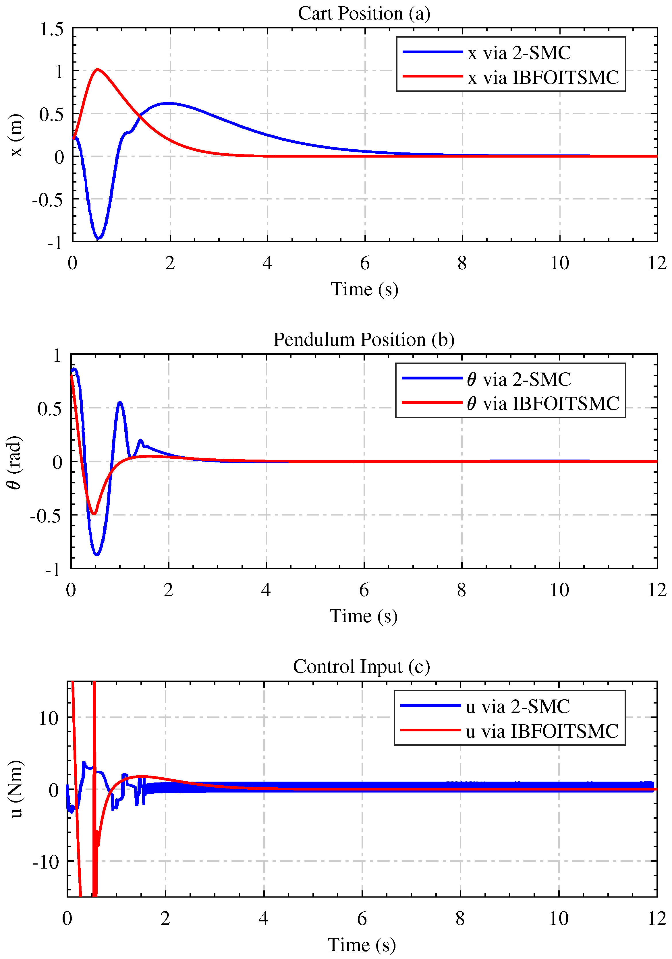
4. Benchmark Example of Cart–Pendulum System
In this section, an integral backstepping strategy is employed to transform the regular form in a generic way, subject to realistic assumptions. An integral sliding mode is developed in the last step, which helps eliminate the reaching phase. Consequently, the system shows more robust behavior from the start of the process compared to conventional sliding modes and traditional nonlinear techniques. The closed-loop stability in each step is proved via Lyapunov stability theory. A diagram of the proposed control scheme is shown in Figure 2.
Figure 2.
Diagram of the cart–pendulum system.
4.1. System Description
The cart–pendulum system is presented as a benchmark example of a UNS with one input and two outputs. The pendulum pole swung freely around the pivot point, whereas the cart could move along the horizontal plane.
The following uncertain dynamics of the aforementioned system are considered:
where , , u is the applied control input, M is the mass of cart, m is the mass of rod, g is the gravitational acceleration, and l denotes rod length. The coordinate transformation converts the dynamics of the cart–pendulum system Equation (37) into the following equivalent regular form []:
where , , and are the position of cart, its velocity, the angular position of pendulum, and its angular velocity, respectively. Note that this model follows all the characteristics of Case-II.
The cart–pendulum system (38) is now ready for the control design presented in Section 4.2.
4.2. Controller Design
The control design using RFOITSMC is now performed by defining the error between the reference position and the actual position of the cart, as follows:
The differentiation of candidate Lyapunov function with respect to time is presented as
For positioning at the desired reference , treating as a virtual control input, the new reference is defined as
where and are the positive control gains and .
Now, is chosen as the mismatch for the next step. The differentiation of can be defined as . For the convergence of error variables and to zero, the time derivative of the Lyapunov function becomes
For the above equation, another new reference, , treated as a virtual control input, is designed as follows:
which yields
where and are the positive control gains and . Using (43), the differentiation of the Lyapunov function yields
Similarly, a new virtual control input is defined to enforce at zero with the following new reference
The time derivative of the Lyapunov function will become
where , are the positive control gains, and and is the mismatch for the last step.
To steer to zero in the presence of matched uncertainties , a robust control law will be designed to enforce sliding mode on the following integral terminal sliding manifold:
The relevant integral dynamic appears as follows:
The control law () for the overall dynamics comes out to be
This control input U provides the benefits and results reported in Case-II.
MATLAB/Simulink simulation results are presented to demonstrate the effectiveness of the proposed control scheme.
4.3. Results Discussion
In the MATLAB/Simulink environment, we compared the results obtained from the simulations using the proposed control scheme with those provided in []. The simulations are evaluated to control the dynamics of the cart–pendulum system via a nonlinear integral backstepping ITSM control technique in the presence of perturbation , which matches in nature. The values of the typical parameters of the cart–pendulum system are chosen to be kg, m/s, kg and m. The initial conditions and reference values of the system’s states are given by and , respectively. The values of the virtual controller and actual controller gains are set to and on a trial-and-error basis.
Figure 3a depicts the asymptotic stability of the cart position. The proposed control law regulation is quite fast, with far more appealing precision compared to the results of []. Similarly, the tracking of the rod angle at the upright position is shown in Figure 3b.
Figure 3.
The position response of IBFOITSMC in comparison with the standard result of [].
The rod angle stability at the equilibrium via the proposed control scheme is far more interesting and practical as compared to its counterpart []. Figure 3a,b shows that the transient response of the proposed control scheme is faster with minimum overshoots and settling time than that in []. In addition, the proposed method offers zero steady-state errors subject to step disturbances because of the proportional-integral-type surface and integral backstepping scheme. Furthermore, the convergence of the system trajectories is unaffected by the matched uncertainty, and the system quickly approaches equilibrium. This confirmed the robustness of the proposed strategy.
The control efforts of both strategies are shown in Figure 3c. It is clear that the control effort of the proposed technique experiences no chattering phenomenon, and behaves in a feasible manner. In other words, the results of [] suffer from substantial chattering, which may damage the systems in practical implementations. Moreover, IBFOISMC significantly attenuated high-frequency oscillations, whereas the control scheme in [] could not handle this problem efficiently. Hence, it is evident from Figure 3a–c of the cart–pendulum system that the proposed stabilizing law offers an appealing dynamic response for a class of UNSs that can be converted to a regular form.
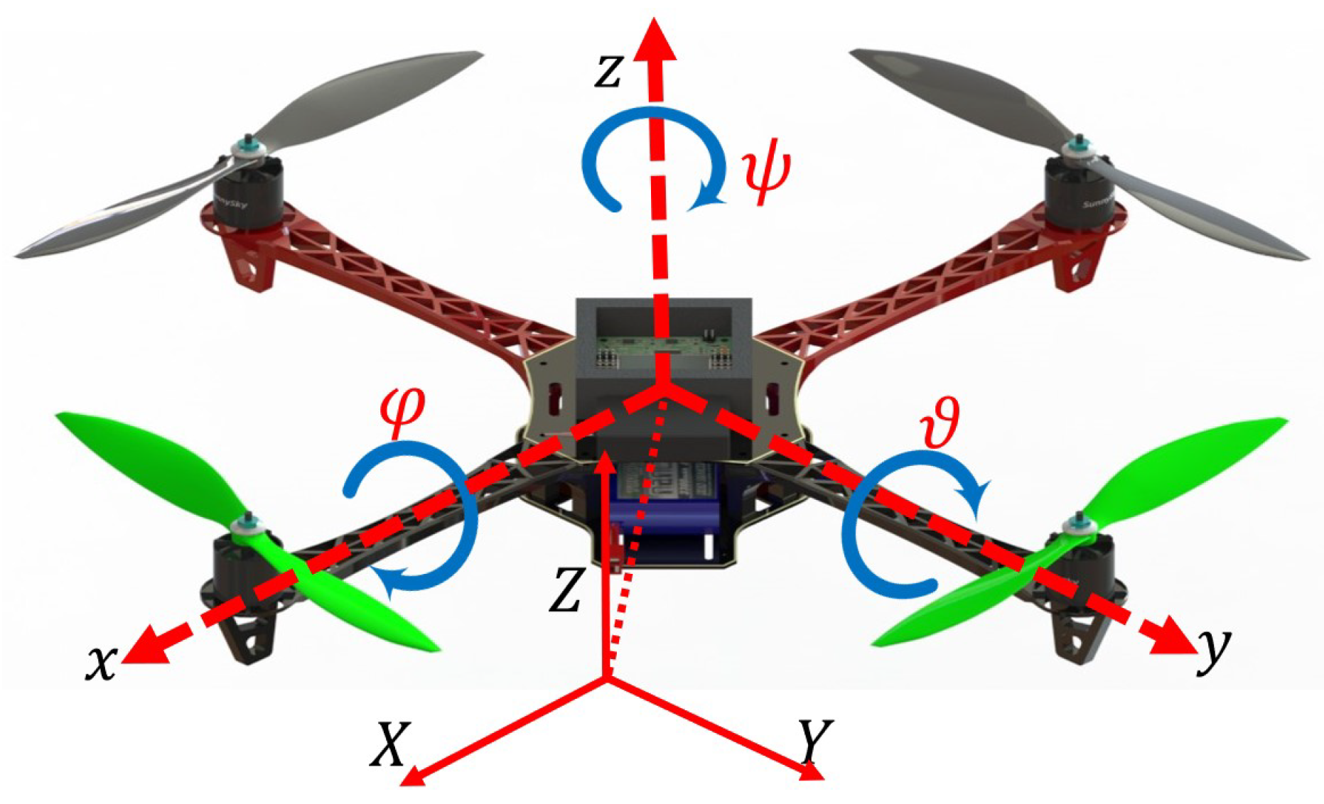
5. Benchmark Example of Quadcopter System
In this section, a complex underactuated quadcopter UAV is tailored using an integrated approach of integral backstepping and integral terminal sliding mode strategies. A diagram of quadcopter UAV is shown in Figure 4.
Figure 4.
The inertial and body frames of a quadcopter UAV.
5.1. System Description
A quadcopter system is typically represented using Euler–Newton or Euler–Lagrange equations of motion within a configuration space consisting of 12 variables. These variables include six for the position and orientation (three for translational positions and three for rotational angles) and six for their respective velocities. The quadcopter dynamics, explicitly expressed in terms of angular positions and velocities, are detailed as follows []:
The parameters included b for the thrust coefficient, d for the drag factor, for rotor inertia, l for arm length, g for gravitational acceleration, and m for quadcopter mass. controls translational motion. The coefficients , , and are related to aerodynamic friction. Additionally, represents the aerodynamic disturbance, where denotes the angular speed of each motor. The thrusts produced by the respective motors for motion along the , , and axes are given by , , and , respectively.
The simulation employed the system parameters described in [].
Remark 3.
In the proposed design, the system is partitioned into fully actuated and underactuated subsystems to ensure that the desired trajectories are followed. In the fully actuated subsystem, the outputs (z and ψ) correspond to the control inputs ( and ). Conversely, in the under-actuated subsystem, there are fewer control inputs ( and ) than the outputs (x, y, φ, and ϑ).
Once transformed into regular form [], the overall state space model of the quadcopter system, as represented by Equation (51), can be expressed as follows:
where , , , and , , , , , and .
Remark 4.
The primary objective of this research is to develop a control algorithm that, even in the presence of matched uncertainties, can track the desired trajectories , , , and , while also stabilizing the pitch and roll angular positions to their respective origins.
The next section presents the proposed control design in detail.
5.2. Control Law Design
Considering the underactuated nature of the quadcopter and the substantial coupling among the rotor inputs, the proposed control strategy is designed to ensure stability in both the under-actuated and fully actuated subsystems.
5.2.1. Fully Actuated Subsystem
The control variable is determined by the error between the reference and actual trajectories, which generates control inputs for the actuators. These inputs adjust the motor speed to achieve desired motion. The reference tracking errors are expressed as follows:
By calculating the time derivatives of the Lyapunov candidate functions and along Equations (52) and (54), the following expressions can be derived:
The variables and are now considered as virtual control inputs to guarantee the negative definiteness of the Lyapunov function’s derivative. Thus, the following selections guide us:
where , , and represent positive gains, while and . Substituting Equation (56) into Equation (55), we obtain
where and are the positive design constants. Moving on, we now consider the previously mentioned and (in Equation (56)) as the new modified references for the states and in the next step.
where and .
In the second step, the goal is for to track , and likewise, for to track . To achieve these goals, integral terminal manifolds are formulated as follows:
where and , and and are positive design constants.
Remark 5.
The proposed control scheme integrates various methodologies to effectively guide the fully actuated subsystem outputs ( and ) towards the desired trajectory. By strategically driving their sliding manifolds to zero within a finite time frame, the system achieved precise trajectory tracking. This involves utilizing the control inputs and , each tailored to manage the system dynamics in the sliding mode. Although and are designed using the pole placement method to ensure effective control, and are crafted through the integral sliding mode approach, initiating the sliding mode from the onset of the process. These control components play a crucial role in achieving precise trajectory tracking, as elaborated in the following theorem.
Theorem 2.
The chosen virtual control laws and , derived from the backstepping procedure, along with the integral terminal sliding manifolds as per Equations (57) and (58), ensure finite-time sliding mode enforcement and asymptotic convergence of the error states with the following control laws:
where , , and are positive design constants.
Proof.
To demonstrate this theorem, examine the time derivative of the sliding manifolds and along Equation (52) as
Equation (61) presents the integral dynamics and governed by the positive constants and , respectively.
Substituting these into Equation (60), we obtain
By analyzing the time derivatives of the extended Lyapunov functions and along Equation (62), we can deduce the following:
In addition to and , pivotal in driving their respective errors to zero, eliminating undesirable terms from the equation, the theorem underscores the significance of employing backstepping-based virtual controllers and . These controllers ensure that and strictly adhere to and , respectively, thereby guaranteeing asymptotic convergence of the fully actuated subsystem states. Moreover, convergence is maintained for the inequalities in Equation (63), valid only for and , where and are small positive values. □
5.2.2. Under-Actuated Subsystem
Before designing the control algorithm for the under-actuated models outlined in Equation (53), it is crucial to highlight their similar dynamic structures. Therefore, to streamline the explanation, we concentrate on presenting the first subsystem Equation (53).
Now, for ensuring the convergence of , the desired sliding surface will be
where the output tracking errors are , and and are positive design constants. The time derivative of Equation (64) can be expressed as
Within the internal dynamic block of Equation (53), represents the state function and functions as a virtual control input. The main objective is to preserve the following structure:
This can be accomplished by selecting
Thus, the sliding surface is defined in the following form:
Applying the first-order sliding mode to Equation (68) yields Equation (67), affirming Equation (66). The first and second derivatives of the above sliding variable (68) can be calculated as follows:
where
Remark 6.
The primary objective of the underactuated subsystem is to steer along a specified trajectory within a finite timeframe while driving ϑ to zero. Achieving this requires ensuring that the sliding variable defined in Equation (68) reaches zero within a finite duration.
In this scenario, is selected as the virtual output and is the control input. Because does not appear in Equation (53), the relative degree increases. Therefore, another integral sliding surface is defined in the following hierarchical form:
where and are the positive design constants.
Remark 7.
The strong robust reachability law, defined with positive constants and , is expressed as follows:
where and are the positive controller constants.
The following theorem offers a detailed analysis of the finite-time stability of the proposed control law for the subsystem.
Theorem 3.
Consider the dynamics of an underactuated subsystem, as defined by Equation (53), assuming full compliance with all of the stated assumptions. Under the proposed sliding surface Equation (71) and the reaching law Equation (72), the following control law ensures finite-time sliding mode enforcement and, consequently, the asymptotic convergence of the error states
Proof.
To validate the stabilization assertion in this theorem, examine the time derivative of Equation (71) alongside the dynamics of Equation (53), as follows
The time derivative of the integral dynamics , with positive design constants , can be represented as follows:
Equation (74) is simplified as follows:
The time derivative of the Lyapunov function along Equation (74) is as follows:
By substituting Equation (72) into Equation (77) and rearranging, we obtain
where . The differential inequality presented in Equation (78) can also be formulated as
where and . Equation (79) encapsulates the extended Lyapunov function, showing the finite-time stability of the aforementioned subsystem through the fractional-order integral terminal sliding mode control methodology. The numerical representation for the settling time is deduced from Equation (79) as follows:
By appropriately choosing these constants, negative definiteness of can be achieved. Consequently, finite-time convergence of to zero is ensured. Similarly, the proposed control law guaranteed the convergence of to zero. □
Remark 8.
Motivated by the structural similarity between the first and second subsystem in Equation (53), a control law is designed as follows:
with . The proposed control law aims to guide ℏ towards and stabilize the dynamics of ϑ at the origin within a finite duration. To achieve this objective, we note that a closely analogous manifold is delineated.
A discussion on tracking under-actuated subsystems has been presented. The following section presents the simulation results for the quadcopter using the RFOITSMC scheme.
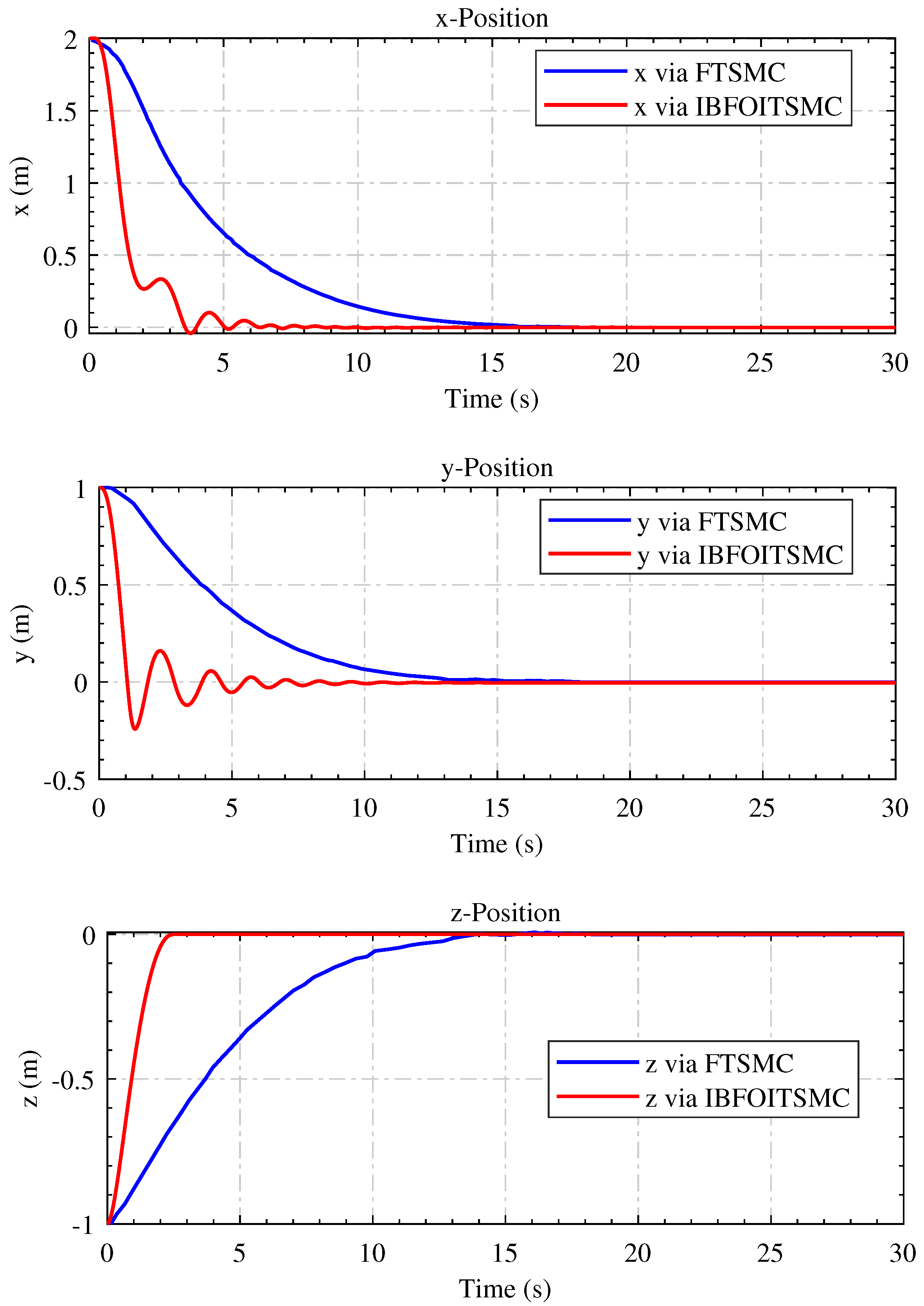
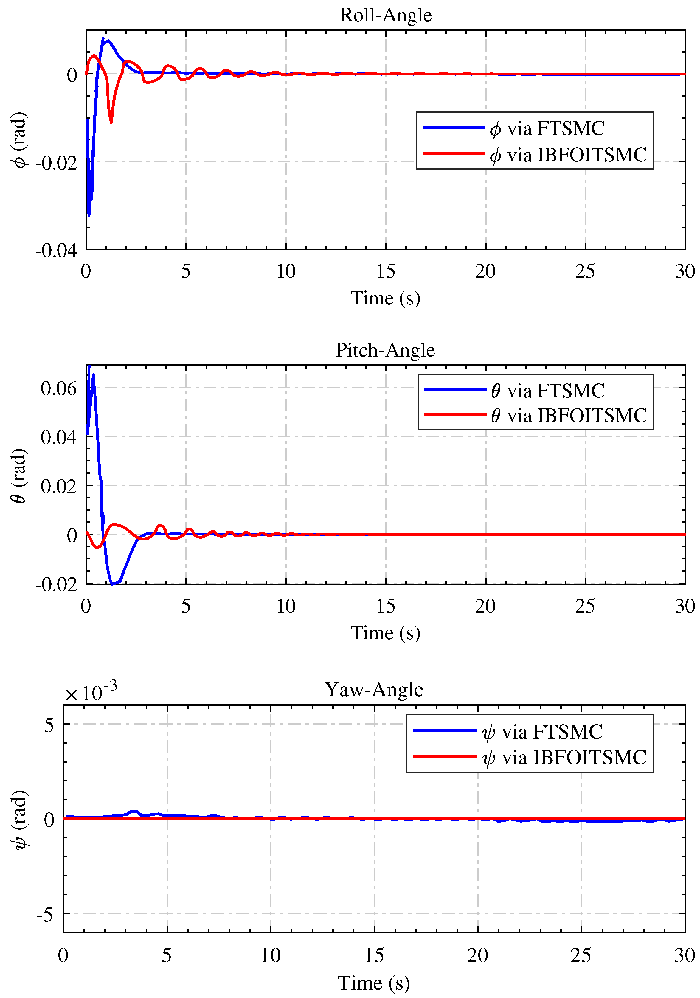
5.3. Simulation Results
In this subsection, we compare the proposed RFOITSMC control algorithm with fixed-time terminal sliding mode control (FTSMC), as presented in []. We emphasize notable performance improvements, including accelerated state convergence, enhanced tracking without chattering, and heightened robustness against system uncertainties. Furthermore, we validated the quadcopter’s dynamic model in the MATLAB/Simulink environment by employing the proposed RFOITSMC control scheme while accounting for matched uncertainties.
Figure 5 provides a detailed comparison of the reference tracking errors along the x, y, and z axes, illustrating discrepancies between the desired and actual trajectories. Similarly, the figures in Figure 6 demonstrate the comparative regulation performance for Euler angles, roll, pitch, and yaw. Notably, the proposed RFOITSMC law effectively minimizes the overshoot and settling time while ensuring a zero steady-state error. This enhancement in the convergence of Euler angles towards equilibrium surpasses the standard results [].
Figure 5.
Comparison of translational trajectory error regulation performance with the standard literature [].
Figure 6.
The comparison of the regulation performance of the angular positions with the standard literature [].
Furthermore, the proposed control scheme effectively mitigates the tracking errors along the translational and rotational axes without inducing chattering, which is a notable advantage over the FOISMC method outlined in []. This smoother trajectory tracking is crucial for real-world applications to ensure more stable and accurate quadcopter maneuvers.
In addition, the robustness of the RIBFOISMC controller against matched uncertainties and from the outset underscores its reliability and stability, even in the presence of such disturbances. Resilience is paramount for ensuring consistent performance under diverse environmental conditions and operational scenarios, enhancing the overall reliability of the control system.
In Figure 7, the control inputs of the proposed scheme exhibit minimal chatter and oscillations compared with their counterparts, which demonstrate significant oscillations. Such oscillations pose risks to the integrity of a system and can degrade its dynamic performance. Stability and performance rely heavily on the initial values of the control inputs and angular velocities, with setting () and to establish a stable starting point. Precise tuning of controller parameters, such as , , , , , , , and , is crucial for effective control action that guides the system’s states towards the desired sliding surface. Additionally, parameters such as , , , and are specifically chosen to enhance the robustness of the system against matched uncertainties.
Figure 7.
The time history of required control input.
6. Conclusions
This paper addresses the control of a highly state-coupled class of under-actuated nonlinear systems. A regular-form conversion is introduced to simplify the control design process, thereby facilitating the application of advanced control techniques to these systems. A step-by-step integral backstepping control strategy is developed for two significant cases: cart–pendulum and quadcopter systems. This approach effectively handled zero dynamics and ensured stability at each design step, which is rigorously verified using the Lyapunov stability approach. In the final design step, an integral-surface-based robust integral terminal fractional-order sliding mode is introduced, which enhances the robustness of the system against uncertainties and provides finite-time stability. Extensive simulations are conducted on the cart–pendulum and quadcopter systems under uncertain conditions, demonstrating that the proposed control strategy achieved superior performance compared with existing methods. Specifically, the proposed method showed significant improvements in robustness, stability, and control precision. Compared to existing methods, the approach offers several improvements: enhanced robustness against uncertainties and disturbances, finite-time stability ensuring rapid convergence to the desired state, and improved handling of highly state-coupled dynamics, making it suitable for complex under-actuated systems.
Author Contributions
Conceptualization, S.U. and H.A.; Methodology, S.U.; Software, S.U. and B.A.; Validation, S.U. and A.A.A.; Formal analysis, H.A., A.A.A., B.A. and G.H.; Resources, H.A. and G.H.; Data curation, A.A.A.; Writing—original draft, S.U.; Writing—review & editing, H.A., A.A.A., B.A. and G.H. All authors have read and agreed to the published version of the manuscript.
Funding
This work is supported by the Taif University, Saudi Arabia through project number (TU-DSPP-2024-285).
Data Availability Statement
The original contributions presented in the study are included in the article, further inquiries can be directed to the corresponding author.
Conflicts of Interest
The authors declare no conflicts of interest.
References
- Huang, Z.; Wang, W.; Zeng, B.; Yu, C.; Zhou, Y. Comprehensive Stable Control Strategy for a Typical Underactuated Manipulator Considering Several Uncertainties. Appl. Sci. 2024, 14, 3663. [Google Scholar] [CrossRef]
- Li, N.; Liu, X.; Liu, C.; He, W.; Wang, H. Adaptive Stabilization Control for a Class of Non-Strict Feedback Underactuated Nonlinear Systems by Backstepping. IEEE Trans. Autom. Sci. Eng. 2024. [Google Scholar] [CrossRef]
- Alsaade, F.W.; Jahanshahi, H.; Yao, Q.; Al-zahrani, M.S.; Alzahrani, A.S. On the Development of a Data-Driven-Based Fractional-Order Controller for Unmanned Aerial Vehicles. Fractal Fract. 2023, 7, 236. [Google Scholar] [CrossRef]
- Shojaei, K.; Chatraei, A. Robust platoon control of underactuated autonomous underwater vehicles subjected to nonlinearities, uncertainties and range and angle constraints. Appl. Ocean Res. 2021, 110, 102594. [Google Scholar] [CrossRef]
- Reis, J.; Yu, G.; Silvestre, C. Kalman-based velocity-free trajectory tracking control of an underactuated aerial vehicle with unknown system dynamics. Automatica 2023, 155, 111148. [Google Scholar] [CrossRef]
- Mija, S. Multiswitching Surface Based Sliding Mode Controller for a Class of Underactuated Nonlinear Systems: With Application to Ball and Plate System. IEEE Trans. Ind. Electron. 2024. [Google Scholar] [CrossRef]
- Ullah, S.; Mehmood, A.; Khan, Q.; Rehman, S.; Iqbal, J. Robust Integral Sliding Mode Control Design for Stability Enhancement of Under-actuated Quadcopter. Int. J. Control. Autom. Syst. 2020, 18, 1671–1678. [Google Scholar] [CrossRef]
- Riachy, S.; Orlov, Y.; Floquet, T.; Santiesteban, R.; Richard, J.P. Second-order sliding mode control of underactuated mechanical systems I: Local stabilization with application to an inverted pendulum. Int. J. Robust Nonlinear Control. IFAC-Affil. J. 2008, 18, 529–543. [Google Scholar] [CrossRef]
- de Groot, O.; Valk, L.; Keviczky, T. Cooperative Passivity-Based Control of Nonlinear Mechanical Systems. Robotics 2023, 12, 142. [Google Scholar] [CrossRef]
- Li, Z.; Zeng, J.; Chen, S.; Sreenath, K. Autonomous navigation of underactuated bipedal robots in height-constrained environments. Int. J. Robot. Res. 2023, 42, 565–585. [Google Scholar] [CrossRef]
- Wu, J.; Zhang, P.; Meng, Q.; Wang, Y. Control of Underactuated Manipulators: Design and Optimization; Springer Nature: Berlin/Heidelberg, Germany, 2023. [Google Scholar]
- Ullah, S.; Khan, Q.; Mehmood, A.; Bhatti, A.I. Robust backstepping sliding mode control design for a class of underactuated electro–mechanical nonlinear systems. J. Electr. Eng. Technol. 2020, 15, 1821–1828. [Google Scholar] [CrossRef]
- Xuan-Mung, N.; Golestani, M.; Nguyen, H.T.; Nguyen, N.A.; Fekih, A. Output feedback control for spacecraft attitude system with practical predefined-time stability based on anti-windup compensator. Mathematics 2023, 11, 2149. [Google Scholar] [CrossRef]
- Yu, K.; Li, Y.; Lv, M.; Tong, S. Adaptive Backstepping Control for Underactuated 6-DoF USV with Uncertain Dynamics. IEEE Trans. Intell. Veh. 2024. [Google Scholar] [CrossRef]
- Yang, N.; Shen, C.; Song, Z.; Johnson-Roberson, M.; Sun, J. Robust Energy-Optimal Control for 3-D Path-Following of Autonomous Underwater Vehicles Under Ocean Currents. IEEE Trans. Control. Syst. Technol. 2023, 32, 680–687. [Google Scholar] [CrossRef]
- Mason, P.; Broucke, M.; Piccoli, B. Time optimal swing-up of the planar pendulum. IEEE Trans. Autom. Control 2008, 53, 1876–1886. [Google Scholar] [CrossRef]
- Kristiansen, B.A.; Gravdahl, J.T.; Johansen, T.A. Energy optimal attitude control for a solar-powered spacecraft. Eur. J. Control 2021, 62, 192–197. [Google Scholar] [CrossRef]
- Cui, Z.; Liu, L.; Zhu, B.; Zhang, L.; Yu, Y.; Zhao, Z.; Li, S.; Liu, M. Spiral Dive Control of Underactuated AUV Based on a Single-Input Fractional-Order Fuzzy Logic Controller. Fractal Fract. 2022, 6, 519. [Google Scholar] [CrossRef]
- Ichida, K.; Watanabe, K.; Izumi, K.; Uchida, N. Fuzzy switching control of underactuated manipulators with approximated switching regions. In Proceedings of the 2006 IEEE/RSJ International Conference on Intelligent Robots and Systems, Beijing, China, 9–15 October 2006; IEEE: New York, NY, USA, 2006; pp. 586–591. [Google Scholar]
- Raguraman, S.; Tamilselvi, D.; Shivakumar, N. Mobile robot navigation using fuzzy logic controller. In Proceedings of the 2009 International Conference on Control, Automation, Communication and Energy Conservation, Perundurai, India, 4–6 June 2009; IEEE: New York, NY, USA, 2009; pp. 1–5. [Google Scholar]
- Aslam, J.; Qin, S.Y.; Alvi, M.A. Fuzzy sliding mode control algorithm for a four-wheel skid steer vehicle. J. Mech. Sci. Technol. 2014, 28, 3301–3310. [Google Scholar] [CrossRef]
- Nguyen, N.P.; Oh, H.; Kim, Y.; Moon, J.; Yang, J.; Chen, W.H. Fuzzy-based super-twisting sliding mode stabilization control for under-actuated rotary inverted pendulum systems. IEEE Access 2020, 8, 185079–185092. [Google Scholar] [CrossRef]
- Mousavi, A.; Markazi, A.H. A predictive approach to adaptive fuzzy sliding-mode control of under-actuated nonlinear systems with input saturation. Int. J. Syst. Sci. 2021, 52, 1599–1617. [Google Scholar] [CrossRef]
- Wang, X.; Duan, G. High-order fully actuated system approaches: Model predictive control with applications to under-actuated systems. J. Frankl. Inst. 2023, 360, 6953–6975. [Google Scholar] [CrossRef]
- Yao, X.Y.; Park, J.H.; Ding, H.F.; Ge, M.F. Event-triggered consensus control for networked underactuated robotic systems. IEEE Trans. Cybern. 2020, 52, 2896–2906. [Google Scholar] [CrossRef] [PubMed]
- Dai, S.L.; He, S.; Cai, H.; Yang, C. Adaptive leader–follower formation control of underactuated surface vehicles with guaranteed performance. IEEE Trans. Syst. Man, Cybern. Syst. 2020, 52, 1997–2008. [Google Scholar] [CrossRef]
- Zheng, W.; Tang, T.L.; Wang, H.B. Distributed leaderless consensus for a class of multiple underactuated systems with unknown nonlinearities and external disturbances. Int. J. Control. Autom. Syst. 2022, 20, 1449–1460. [Google Scholar] [CrossRef]
- Ullah, S.; Khan, Q.; Mehmood, A.; Akmeliawati, R. Integral backstepping based robust integral sliding mode control of underactuated nonlinear electromechanical systems. J. Control Eng. Appl. Inf. 2019, 21, 42–50. [Google Scholar]
- Ullah, S.; Khan, Q.; Zaidi, M.M.; Hua, L.G. Neuro-adaptive non-singular terminal sliding mode control for distributed fixed-time synchronization of higher-order uncertain multi-agent nonlinear systems. Inf. Sci. 2024, 659, 120087. [Google Scholar] [CrossRef]
- Ullah, S.; Khan, Q.; Mehmood, A. Neuro-adaptive fixed-time non-singular fast terminal sliding mode control design for a class of under-actuated nonlinear systems. Int. J. Control 2023, 96, 1529–1542. [Google Scholar] [CrossRef]
- Yang, T.; Chen, H.; Sun, N.; Fang, Y. Adaptive neural network output feedback control of uncertain underactuated systems with actuated and unactuated state constraints. IEEE Trans. Syst. Man, Cybern. Syst. 2021, 52, 7027–7043. [Google Scholar] [CrossRef]
- Efe, M.Ö. Integral sliding mode control of a quadrotor with fractional order reaching dynamics. Trans. Inst. Meas. Control 2011, 33, 985–1003. [Google Scholar] [CrossRef]
- Shi, X.; Cheng, Y.; Yin, C.; Dadras, S.; Huang, X. Design of fractional-order backstepping sliding mode control for quadrotor UAV. Asian J. Control 2019, 21, 156–171. [Google Scholar] [CrossRef]
- Qi, W.; Zong, G.; Karim, H.R. Observer-based adaptive SMC for nonlinear uncertain singular semi-Markov jump systems with applications to DC motor. IEEE Trans. Circuits Syst. I Regul. Pap. 2018, 65, 2951–2960. [Google Scholar] [CrossRef]
- Bartolini, G.; Ferrara, A.; Usai, E. Chattering avoidance by second-order sliding mode control. IEEE Trans. Autom. Control 1998, 43, 241–246. [Google Scholar] [CrossRef]
- Levant, A. Quasi-continuous high-order sliding-mode controllers. In Proceedings of the 42nd IEEE Conference Proceedings on Decision and Control, Maui, HI, USA, 9–12 December 2003; IEEE: New York, NY, USA, 2003; Volume 5, pp. 4605–4610. [Google Scholar]
- Utkin, V.; Guldner, J.; Shi, J. Sliding Mode Control in Electro-Mechanical Systems; CRC Press: Boca Raton, FL, USA, 2009. [Google Scholar]
- Khan, Q.; Akmeliawati, R.; Bhatti, A.I.; Khan, M.A. Robust stabilization of underactuated nonlinear systems: A fast terminal sliding mode approach. ISA Trans. 2017, 66, 241–248. [Google Scholar] [CrossRef] [PubMed]
- Olfati-Saber, R. Nonlinear Control of Underactuated Mechanical Systems with Application to Robotics and Aerospace Vehicles. Ph.D. Thesis, Massachusetts Institute of Technology, Cambridge, MA, USA, 2001. [Google Scholar]
- Bouabdallah, S. Design and Control of Quadrotors with Application to Autonomous Flying; Technical Report; Epfl: Lausanne, Switzerland, 2007. [Google Scholar]
- Ullah, S.; Khan, Q.; Mehmood, A.; Kirmani, S.A.M.; Mechali, O. Neuro-adaptive fast integral terminal sliding mode control design with variable gain robust exact differentiator for under-actuated quadcopter UAV. ISA Trans. 2022, 120, 293–304. [Google Scholar] [CrossRef] [PubMed]
- Yun, H.; Zongyu, Z.; Zhiguang, S. Fixed-time terminal sliding mode trajectory tracking control of quadrotor helicopter. In Proceedings of the 2015 34th Chinese Control Conference (CCC), Hangzhou, China, 28–30 July 2015; IEEE: New York, NY, USA, 2015; pp. 4361–4366. [Google Scholar]
Disclaimer/Publisher’s Note: The statements, opinions and data contained in all publications are solely those of the individual author(s) and contributor(s) and not of MDPI and/or the editor(s). MDPI and/or the editor(s) disclaim responsibility for any injury to people or property resulting from any ideas, methods, instructions or products referred to in the content. |
© 2024 by the authors. Licensee MDPI, Basel, Switzerland. This article is an open access article distributed under the terms and conditions of the Creative Commons Attribution (CC BY) license (https://creativecommons.org/licenses/by/4.0/).