Article

Time-Delay Effects on the Collective Resonant Behavior in Two Coupled Fractional Oscillators with Frequency Fluctuations

1
College of Computer and Information Science, Fujian Agriculture and Forestry University, Fuzhou 350002, China
2
College of Mathematics and Statistics, Chongqing University, Chongqing 401331, China
*
Authors to whom correspondence should be addressed.
Fractal Fract. 2024, 8(5), 287; https://doi.org/10.3390/fractalfract8050287
Submission received: 30 March 2024 / Revised: 1 May 2024 / Accepted: 7 May 2024 / Published: 11 May 2024
(This article belongs to the Section Mathematical Physics)

Abstract

:
In this study, we propose coupled time-delayed fractional oscillators with dichotomous fluctuating frequencies and investigate the collective resonant behavior. Firstly, we obtain the condition of complete synchronization between the average behavior of the two oscillators. Subsequently, we derive the precise analytical expression of the output amplitude gain. Based on the analytical results, we observe the collective resonant behavior of the coupled time-delayed system and further study its dependence on various system parameters. The observed results underscore that the coupling strength, fractional order, and time delay play significant roles in controlling the collective resonant behavior by facilitating the occurrence and optimizing the intensity. Finally, numerical simulations are also conducted and verify the accuracy of the analytical results.

1. Introduction

Ever since Benzi et al. [1] first introduced the concept of “stochastic resonance” (SR), it has garnered extensive attention across various disciplines such as physics, biology, and chemistry [2,3,4,5,6,7,8,9]. Early investigations indicated that the essential prerequisites for inducing SR involve a nonlinear system, a weak periodic signal, and the presence of additive noise. Consequently, earlier research predominantly concentrated on exploring SR behavior in nonlinear systems driven by additive noise [10,11,12,13]. However, subsequent studies have revealed that SR phenomena can occur in linear systems driven by multiplicative noise [14,15,16,17]. Here, the preference for linear systems in subsequent research mainly stems from their ease of solution and widespread applicability [15].
A coupled system refers to a system consisting of finite (or infinite) local (or global) coupled elements [18], such as complex networks, where the particles are interconnected, making the coupled model crucial for accurately describing real-world problems. Consequently, there is a growing interest among scholars in exploring SR within coupled systems [19,20,21,22,23,24,25]. For instance, Vishwamittar et al. [19] delved into the study of collective resonant behavior in two coupled fractional oscillators subjected to quadratic asymmetric dichotomous noise. Yu et al. [20] proposed a model featuring two coupled fractional harmonic oscillators with fluctuating masses and investigated the SR phenomena through a combination of numerical and theoretical solutions. Lin et al. [21] explored the collective resonant behavior of coupled oscillators with fluctuating masses and incorporated a tempered Mittag–Leffler memory kernel. The coupling mechanism employed in this study involves linear interaction between the two oscillators, akin to the relationship between any two particles in a globally coupled system [22,23] or the connection between the two nearest particles in a nearest-neighbor coupling system [24,25].
In the context of evolving complex networks, the role of time delays becomes pivotal in the exploration of dynamic phenomena. Time delays are omnipresent in nature due to limitations in signal propagation, response times, and switching speeds [26]. Notably, Guillouzi et al. [27,28] introduced the small delay approximation, which is a novel method utilized for the first time to address stochastic differential equations featuring delay terms. Zhong et al. [29] extended the exploration by proposing a time-delayed fractional oscillator with fluctuation damping and investigating the generalized SR phenomena. In a related vein, Li et al. [30] observed that SR can be either enhanced or suppressed by manipulating the delay time and feedback strength. Concurrently, Jin et al. [31] investigated coherence resonance and SR in a time-delayed bistable system driven by both additive and multiplicative white noises. In addition, fractional models [32,33,34] are more suitable for describing memory effects and non-local behavior, and some numerical methods [35,36,37] have been proposed for solving fractional integro–differential equations. Therefore, generalized SR in time-delay fractional oscillators with random masses [38,39], random damping [40,41], and random frequencies [42] has been recently investigated through theoretical analysis and numerical calculations.
Furthermore, it is worth noting that all the aforementioned studies focused on the time-delayed stochastic differential model of individual particles, neglecting the consideration of interactions or coupling between particles. In reality, both time-delay and inter-particle coupling are prevalent in natural systems, leading to the proposition and exploration of numerous coupled models incorporating time delays. For instance, Kim et al. [43] delved into the dynamic behavior of coupled oscillators with time-delayed interaction: specifically under the influence of a pinning force. In a related study, Banerjee et al. [44] introduced the synchronization phenomenon in coupled hyperchaotic electronic oscillators featuring time delays. Additionally, Zhang et al. [45] investigated the SR phenomena exhibited in coupled systems with time delays while considering the impacts of mass and frequency fluctuations and further applied these findings to the diagnosis of bearing faults. Meanwhile, the influence of time delays on SR and discharge frequency oscillations within cortical neural networks is thoroughly analyzed in [46].
Nevertheless, limited attention has been given in the existing literature to the combined impact of time delays and frequency fluctuations in coupled fractional systems. Therefore, in this paper, we propose a novel system model featuring two coupled fractional oscillators with both time delay and frequency fluctuations and study the collective resonant behavior through a comprehensive exploration employing both theoretical and numerical methods. The primary outcomes of this investigation encompass the statistical synchronization observed between the two particles and the influences of coupling, time delay, and fractional order on the collective resonant behavior.
The subsequent sections are organized as follows: In Section 2, a detailed presentation of the system model outlining the characteristics of two coupled time-delayed fractional oscillators with frequency fluctuations is provided. Then, the analytical expression of the output amplitude gain is derived. Section 3 employs numerical results to scrutinize the collective resonant behavior in the proposed system. In Section 4, a numerical simulation is conducted to corroborate the analytical results. Finally, the succinct conclusions are summarized in Section 5.

2. System Model

We consider two coupled time-delayed fractional oscillators with frequency fluctuations that are described by the following fractional Langevin equations:
m x ¨ 1 ( t ) + γ 0 C D t α x 1 ( t ) + ω 2 + ξ 1 ( t ) x 1 ( t τ ) = ε x 2 ( t ) x 1 ( t ) + R cos ( Ω t ) + ζ 1 ( t ) ,
m x ¨ 2 ( t ) + γ 0 C D t α x 2 ( t ) + ω 2 + ξ 2 ( t ) x 2 ( t τ ) = ε x 1 ( t ) x 2 ( t ) + R cos ( Ω t ) + ζ 2 ( t ) ,
where x i ( t ) is the displacement of the ith particle at time t, i = 1 , 2 , and γ > 0 is the damping coefficient, ω represents the system’s intrinsic frequency, τ > 0 is the time delay, and R and Ω represent the amplitude and frequency, respectively, of the periodic driving force. Moreover, ε is the coupling strength, and the two particles interact through the linear coupling term ± ε x 2 x 1 . The viscous damping force related to the memory effect is defined by fractional derivatives with α -order Caputo form:
γ 0 C D t α x i ( t ) = γ 0 t 1 Γ ( 1 α ) | t s | α x ˙ i ( s ) d s , 0 < α 1 .
In the Equations (1) and (2), the internal noise terms ζ 1 ( t ) and ζ 2 ( t ) are fractional Gaussian noise and are supposed to satisfy the generalized second fluctuation–dissipation theorem [47]:
ζ i ( t ) = 0 , ζ i ( t ) ζ i ( s ) = γ κ B T Γ ( 1 α ) | t s | α , i = 1 , 2 .
Here, the frequency fluctuations ξ 1 ( t ) and ξ 2 ( t ) are modeled as uncorrelated symmetric dichotomous noises taking two values ξ i ( t ) { σ , σ } , i = 1 , 2 , , for which the statistical properties are represented as follows:
ξ i ( t ) = 0 , ξ i ( t ) ξ j ( s ) = δ i j σ 2 e λ | t s | , i = 1 , 2 ,
where σ and λ are the noise intensity and correlation rate, respectively. Further, ξ i ( t ) and ζ i ( t ) , i = 1 , 2 , are reasonably supposed to be uncorrelated due to their different origins; that is,
ξ i ( t ) ζ j ( s ) = 0 , i , j = 1 , 2 .
As mentioned in [20], the internal noises ζ i ( t ) lose their effect on the first moments x i ( t ) , i = 1 , 2 , based on the general assumptions (Equations (4) and (6)). In this study, we only focus on the first-order moment of the system’s steady response; therefore, ζ 1 ( t ) and ζ 2 ( t ) can be reasonably ignored for simplicity in form. In addition, we first perform the O ( τ 2 ) Taylor expansion around τ = 0 on the term x ( t τ ) and obtain the following equivalent fractional Langevin equations without time delays:
m x ¨ 1 ( t ) + γ 0 C D t α x 1 ( t ) + ω 2 + ξ 1 ( t ) x 1 ( t ) τ x ˙ 1 ( t ) = ε x 2 ( t ) x 1 ( t ) + R cos ( Ω t ) ,
m x ¨ 2 ( t ) + γ 0 C D t α x 2 ( t ) + ω 2 + ξ 2 ( t ) x 2 ( t ) τ x ˙ 2 ( t ) = ε x 1 ( t ) x 2 ( t ) + R cos ( Ω t ) .
It should be noted that the Equations (7) and (8) is an approximation of the Equations (1) and (2) only in the situation of a small time delay.

2.1. Complete Synchronization between the Average Behavior of the Two Oscillators

To analyze the collective resonant behavior of the coupled system (Equations (7) and (8)), it is imperative to assess whether the average behavior of the two particles is synchronized, which leads us to need to calculate x 1 ( t ) x 2 ( t ) . In order to analyze the stationary state response of the Equations (7) and (8), we introduce the widely recognized Shapiro–Loginov formulas [48] and their generalized form [18] as preparation:
ξ i ( t ) d n x j ( t ) d t n = d d t + λ n ξ i ( t ) x j ( t ) , i , j = 1 , 2 ,
ξ 1 ( t ) ξ 2 ( t ) d n x j ( t ) d t n = d d t + 2 λ n ξ 1 ( t ) ξ 2 ( t ) x j ( t ) , j = 1 , 2 ,
and
ξ i ( t ) 0 C D t α x j ( t ) = e λ t   0 C D t α ξ i ( t ) x j ( t ) e λ t , i , j = 1 , 2 ,
ξ 1 ( t ) ξ 2 ( t ) 0 C D t α x j ( t ) = e 2 λ t   0 C D t α ξ 1 ( t ) ξ 2 ( t ) x j ( t ) e 2 λ t , j = 1 , 2 ,
which are important in the calculation process.
Firstly, by subtracting Equation (8) from Equation (7) we obtain
m d 2 d t 2 + γ 0 C D t α + ω 2 τ ω 2 d d t + 2 ε x 1 ( t ) x 2 ( t ) + ξ 1 ( t ) x 1 ( t ) ξ 2 ( t ) x 2 ( t ) τ ξ 1 ( t ) d d t x 1 ( t ) ξ 2 ( t ) d d t x 2 ( t ) = 0 .
Then, we perform three operations on Equation (13): (I) averaging it with respect to the noise, (II) multiplying it by ξ 1 ( t ) + ξ 2 ( t ) and then averaging, and (III) multiplying it by ξ 1 ( t ) ξ 2 ( t ) and then averaging. By using the Shapiro–Loginov formulas (9)–(12), we obtain
m d 2 d t 2 + γ 0 C D t α + ω 2 τ ω 2 d d t + 2 ε x 1 ( t ) x 2 ( t ) + 1 τ d d t + λ ξ 1 ( t ) x 1 ( t ) ξ 2 ( t ) x 2 ( t ) = 0 ,
m d d t + λ 2 + ω 2 τ ω 2 d d t + λ + 2 ε ξ 1 ( t ) x 1 ( t ) ξ 2 ( t ) x 2 ( t ) + ξ 2 ( t ) x 1 ( t ) ξ 1 ( t ) x 2 ( t ) + γ e λ t   0 C D t α ξ 1 ( t ) x 1 ( t ) ξ 2 ( t ) x 2 ( t ) + ξ 2 ( t ) x 1 ( t ) ξ 1 ( t ) x 2 ( t ) e λ t + σ 2 1 τ d d t x 1 ( t ) x 2 ( t ) + 1 τ d d t + 2 λ ξ 1 ( t ) ξ 2 ( t ) x 1 ( t ) x 2 ( t ) = 0 ,
m d d t + 2 λ 2 + ω 2 τ ω 2 d d t + 2 λ + 2 ε ξ 1 ( t ) ξ 2 ( t ) x 1 ( t ) x 2 ( t ) + γ e 2 λ t   0 C D t α ξ 1 ( t ) ξ 2 ( t ) x 1 ( t ) x 2 ( t ) e 2 λ t + σ 2 1 τ d d t + λ ξ 2 ( t ) x 1 ( t ) ξ 1 ( t ) x 2 ( t ) = 0 .
Next, we multiply the Equations (7) and (8) by ξ 1 ( t ) and ξ 2 ( t ) , respectively, and then we subtract the two results. We further average the obtained equation, utilize the Shapiro–Loginov formulas (9)–(12) again, and have
m d d t + λ 2 + ω 2 τ ω 2 d d t + λ + ε ξ 1 ( t ) x 1 ( t ) ξ 2 ( t ) x 2 ( t ) + ε ξ 2 ( t ) x 1 ( t ) ξ 1 ( t ) x 2 ( t ) + γ e λ t   0 C D t α ξ 1 ( t ) x 1 ( t ) ξ 2 ( t ) x 2 ( t ) e λ t + σ 2 1 τ d d t x 1 ( t ) x 2 ( t ) = 0 .
Hence, we get closed Equations (14)–(17) with four newly defined variables: y 1 x 1 ( t ) x 2 ( t ) , y 2 ξ 1 ( t ) x 1 ( t ) ξ 2 ( t ) x 2 ( t ) , y 3 ξ 2 ( t ) x 1 ( t ) ξ 1 ( t ) x 2 ( t ) , y 4 ξ 1 ( t ) ξ 2 ( t ) x 1 ( t ) x 2 ( t ) . In the long-time limit of t , the influence of the initial conditions on the system’s stationary state response gradually disappears. Subsequently, we solve closed Equations (14)–(17) by using Laplace and inverse Laplace transforms, and we obtain the following important results:
lim t y 1 = lim t y 2 = lim t y 3 = lim t y 4 = 0 ,
which can be rewritten as
x 1 ( t ) as = x 2 ( t ) as = lim t x 1 ( t ) , ξ 1 ( t ) x 1 ( t ) as = ξ 2 ( t ) x 2 ( t ) as = lim t ξ 1 ( t ) x 1 ( t ) , ξ 2 ( t ) x 1 ( t ) as = ξ 1 ( t ) x 2 ( t ) as = lim t ξ 2 ( t ) x 1 ( t ) , ξ 1 ( t ) ξ 2 ( t ) x 1 ( t ) as = ξ 1 ( t ) ξ 2 ( t ) x 2 ( t ) as = lim t ξ 1 ( t ) ξ 2 ( t ) x 1 ( t ) .
It can be concluded by Equation (19) that the average of the mean field is equal to the average of any single particle’s displacement in the long-time limit, i.e., ( x 1 ( t ) + x 2 ( t ) ) / 2 as = x 1 ( t ) as = x 2 ( t ) as , which shows that the average behavior of the two particles is completely synchronized. In addition, the results ensure the rationality and validity to study the mean field through x 1 ( t ) . Therefore, we only analyze one particle’s stationary state response x 1 ( t ) in the following subsection.

2.2. Output Amplitude Gain Of System

We perform four operations on Equation (7): (I) averaging it with respect to the noise, (II) multiplying it by ξ 1 ( t ) and then averaging, (III) multiplying it by ξ 2 ( t ) and then averaging, and (IV) multiplying it by ξ 1 ( t ) ξ 2 ( t ) and then averaging. Then, we utilize the Shapiro–Loginov formulas (9)–(12) and the results in Equations (19) again, and thus we obtain the closed equations with four new variables as follows:
m d 2 d t 2 + γ 0 C D t α τ ω d d t + ω 2 z 1 ( t ) + 1 τ d d t + λ z 2 ( t ) = R cos ( Ω t ) ,
m d d t + λ 2 τ ω 2 d d t + λ + ω 2 + ε z 2 ( t ) + γ e λ t   0 C D t α z 2 ( t ) e λ t + σ 2 1 τ d d t z 1 ( t ) ε z 3 ( t ) = 0 ,
m d d t + λ 2 τ ω 2 d d t + λ + ω 2 + ε z 3 ( t ) + γ e λ t   0 C D t α z 3 ( t ) e λ t ε z 2 ( t ) + 1 τ d d t + 2 λ z 4 ( t ) = 0 ,
m d d t + 2 λ 2 τ ω 2 d d t + 2 λ + ω 2 z 4 ( t ) + σ 1 τ d d t + λ z 3 ( t ) + γ e 2 λ t   0 C D t α z 4 ( t ) e 2 λ t = 0 ,
where z 1 ( t ) x 1 ( t ) , z 2 ( t ) ξ 1 ( t ) x 1 ( t ) , z 3 ( t ) ξ 2 ( t ) x 1 ( t ) , z 4 ( t ) ξ 1 ( t ) ξ 2 ( t ) x 1 ( t ) .
Solving closed Equations (20)–(23) by the Laplace transform, we obtain
a 11 a 12 0 0 a 21 a 22 a 23 0 0 a 32 a 33 a 34 0 0 a 43 a 44 Z 1 Z 2 Z 3 Z 4 = R s s 2 + Ω 2 0 0 0 ,
where the elements a i j are given by
a 11 = m s 2 + γ s α τ ω 2 s + ω 2 , a 22 = m s + λ 2 τ ω 2 s + λ + γ s + λ α + ω 2 + ε , a 12 = 1 τ s + λ , a 33 = m s + λ 2 τ ω 2 s + λ + γ s + λ α + ω 2 + ε , a 21 = σ 2 τ σ 2 s , a 32 = ε , a 23 = ε , a 34 = 1 τ s + 2 λ , a 43 = σ 2 1 τ s + λ , a 44 = m s + 2 λ 2 τ ω 2 s + 2 λ + γ s + 2 λ α + ω 2 ,
and Z i ( s ) = L { z i ( t ) } = 0 + z i ( t ) e s t d t is the Laplace transform of z i ( t ) , i = 1 , 2 , 3 , 4 .
To derive the steady-state response of the system, we focus only on the solution for Z 1 ( s ) , which can be express by
Z 1 ( s ) = H 1 ( s ) R s s 2 + Ω 2 ,
where
H 1 ( s ) = g ( s ) f ( s ) , g ( s ) = a 22 a 33 a 44 a 22 a 34 a 43 a 23 a 32 a 44 , f ( s ) = a 11 a 22 a 33 a 44 a 11 a 22 a 34 a 43 a 11 a 23 a 32 a 44 a 12 a 21 a 33 a 44 + a 12 a 21 a 34 a 43 .
Applying the inverse Laplace transform to Equation (25), we get the analytical expression of x 1 ( t ) as follows:
x 1 ( t ) = R 0 t h 1 ( t t ) cos ( Ω t ) d t ,
where h 1 ( t ) is the inverse Laplace transform of H 1 ( s ) . Similarly, in a long-time limit t , the effect of the initial conditions on the system’s stationary state response x ( t ) as vanishes, and thus, x ( t ) as can be asymptotically expressed as
x ( t ) as = x 1 ( t ) as = A as cos ( Ω t + φ as ) ,
where A as and φ as are the amplitude and phase shift, respectively, of x ( t ) as . More specifically, A as and φ as can be expressed as
A as = R | H 1 ( j Ω ) | = R u 1 2 + u 2 2 u 3 2 + u 4 2 ,
and
φ as = arg H 1 ( j Ω ) = arctan u 2 u 3 u 1 u 4 u 1 u 3 + u 2 u 4 ,
where j is the imaginary unit, and the related coefficients are arranged in Appendix A.
Finally, the output amplitude gain is given by
G = A as R = u 1 2 + u 2 2 u 3 2 + u 4 2 .

3. Collective Resonant Behavior

This section is dedicated to analyzing the collective resonant behavior of the two coupled time-delayed fractional oscillators with fluctuating frequencies in terms of the analytical expression of output amplitude gain G (30). Specifically, we mainly focus on investigating the synergistic effects of the coupling strength ε , time delay τ , fractional order α , and noise parameters ( σ 2 , λ ) on the collective resonant behavior, including collective parameter-induced SR and collective conventional SR behaviors. Here, the parameter-induced SR phenomenon is presented by changing system parameters with fixed noise [49], and the conventional SR phenomenon is presented by adjusting the noise intensity σ 2 and correlation rate λ with fixed system parameters.

3.1. Collective Parameter-Induced SR based on System Parameters

Firstly, we present the phase diagram in the σ α plane in Figure 1 to analyze the emergence of collective parameter-induced SR in G ( ε ) both with and without a time delay (i.e., τ = 0 , 0.05 ). The gray region indicates that single-peak collective parameter-induced SR takes place, while the white region signifies there is no collective resonant behavior. Figure 1a shows that collective parameter-induced SR only occurs in the strong-memory region ( α < 0.45 , except for α = 0 ). A smaller α with stronger memory can induce the collective parameter-induced SR phenomena. Figure 1b indicates that when a time delay exists in the system ( τ = 0.05 ), the resonant region evidently gets larger, suggesting that the time delay also can induce collective parameter-induced SR. Actually, both small α values and large τ values reflect strong memory effects to control the emergence of collective parameter-induced SR. Without loss of generality, we take τ = 0.05 as an example and further analyze the effects of α and σ on G ( ε ) . As shown in Figure 1c, an increase in α results in a decrease in the peak value of G ( ε ) , accompanied by an obvious leftward shift in the peak position. Conversely, as shown in Figure 1d, the resonance peak of G ( ε ) is observed to rise with an increase in noise intensity σ , accompanied by a slightly leftward shift in the peak position.
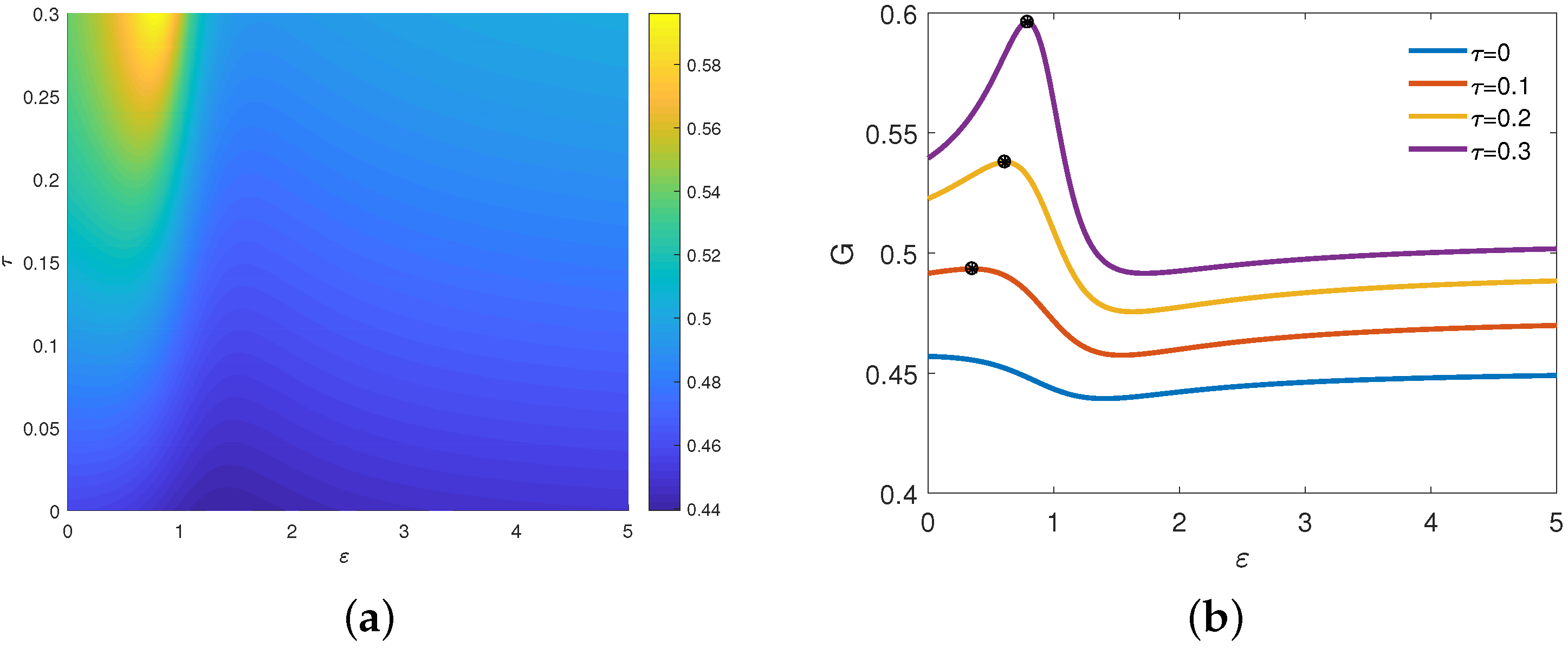
To further explore the effect of the small time delay τ on G ( ε ) , we plot the nephogram of G ( ε , τ ) and the curves depicting G ( ε ) for various values of τ . As depicted in Figure 2, G varies non-monotonously with increasing ε , indicating the occurrence of the collective parameter-induced SR phenomenon with one peak. It is evident in Figure 2b that the peak value experiences a sharp increase with increasing τ , and the peak position shifts to the right. It follows then that increasing τ and decreasing α , reflecting strong system memory, can increase the maxima of G ( ε ) (see Figure 1c and Figure 2b). Furthermore, another observation from the figures reveals that in the weakly coupled region, G exhibits a non-monotonic variation with an increase in ε , while in the strongly coupled region, the curves converge to a limit value. This phenomenon can be interpreted as follows: when ε reaches a sufficiently large value ε * , the coupling forces ± ε ( x 1 x 2 ) become relatively large, compelling the two particles to move cohesively. Consequently, any further increase in ε does not impact the motion of the two particles, resulting in a constant value of G rather than a change, indicating that it stabilizes at a fixed value.
In order to have a deeper insight on the influence of τ on G, we plot Figure 3, in which we show the curves of G ( τ ) for various ε and α values. Notably, all the curves exhibit a discernible peak, signifying that the collective parameter-induced SR appears. As shown in Figure 3a, there is complex change in G ( τ ) . As ε increase, G ( τ ) rises first and falls rapidly later. After arriving at the bottom, G ( τ ) creeps up again and tends to a fixed limit (also see Figure 2b). Moreover, the peak position of G ( τ ) moves to the larger τ , meaning stronger system memory. As shown in Figure 3b, as α increase, the peak value of G ( τ ) decreases, with the peak position moving to the larger value of τ . We can conclude that there is a smallest system memory with a combination of a fractional order α and time delay τ that can induce optimal matching between the system and noise when other system parameters are fixed. Thus, the peak position τ c r moves to the right as α increase. That is, the weakening of memory brought by increasing α offsets the enhancement of memory caused by increasing τ .
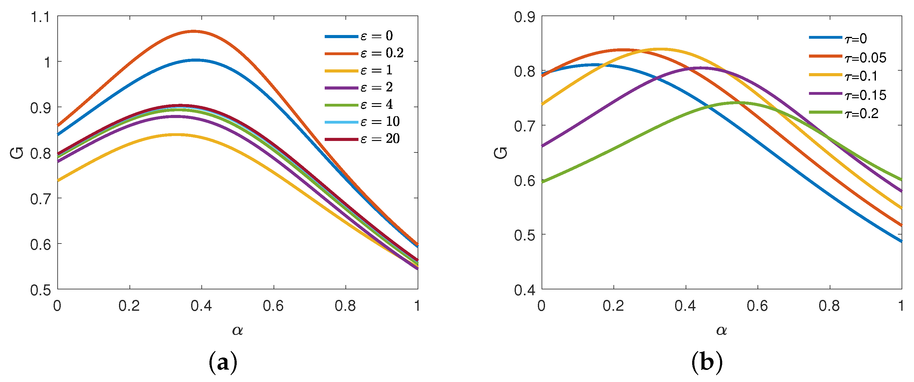
Similarly, the impact of α on G is investigated in Figure 4, in which we present the curves of G ( α ) for various ε and τ values. The non-monotonous curves of G ( α ) mean that collective parameter-induced SR occurs. Comparing with Figure 3a, G ( α ) exhibits a similar variation trend as ε increases in Figure 4a, but the peak position of G ( α ) moves slightly to the smaller α , which also means stronger system memory. As shown in Figure 4b, the peak value of G ( α ) first increases and then decreases with increasing τ , and the peak position moves to the larger value of α significantly. Here, the enhancement of memory brought by increasing τ also offsets the decay to memory caused by increasing α .

3.2. Collective Conventional SR based on Noise Parameters

Finally, we delve into the dependence of the output amplitude gain G on the noise intensity σ and correlation rate λ . Figure 5 and Figure 6, respectively, illustrates the curves of G ( σ ) and G ( λ ) for varying values ε , τ , and α ; the figures show non-monotonous behavior signifying the occurrence of collective conventional SR phenomena.
As shown in Figure 5a, the peak value of G ( σ ) varies non-monotonically as ε increases: specifically, increasing first and then decreasing until it remains unchanged. There is also an interesting phenomenon in the peak position in that it moves to the right initially and then moves to the left. We can see from Figure 5b that with an increase in τ , the peak value of G ( σ ) increases, and the peak position shifts to the larger value of σ . Furthermore, the similar influence of α on G ( σ ) is shown in Figure 5c. As system memory is enhanced, as reflected by decreasing α , the peak value of G ( σ ) increases quickly, and the peak position shifts to the larger value of σ slightly. Obviously, both increasing τ and decreasing α can enhance the intensity of collective conventional SR. The phenomena can be attributed to the fact that the increase in system memory is beneficial for transferring noise energy to periodic signals.
In Figure 6a, it is evident that the peak value of G ( λ ) rises with an increase in ε , and the peak position shifts to the left. This result signifies that an appropriately chosen coupling strength ε can enhance the collective resonant intensity. As in Figure 6b, the presence of a time delay leads to the occurrence of collective conventional SR with one peak and one valley. As τ increases, G ( λ ) increases and reaches a maximum at a larger λ . In Figure 6c, there is no resonance behavior observed for α 0.6 . However, for α < 0.6 , a decrease in α leads to a increase in the peak value accompanied by a rightward shift in the peak position. The phenomena observed in Figure 6b,c can be elucidated as follows. Time delay τ and fractional order α reflect the memory characteristics of the system, and their effects are opposite. Meanwhile, the noise correlation rate λ reflects the memory characteristics of the noise. Specifically, a larger λ represents weaker memory of the noise. The system’s memory effect resulting from an increase in τ or a decrease in α necessitates a larger noise correlation rate to counteract it. In addition, it can be concluded from Figure 6 that ε , τ , and α play a significant role in controlling the collective conventional SR intensity of G ( λ ) .

4. Numerical Simulation

In this section, we present numerical simulations to validate the credibility and precision of the analytical results. Utilizing the Grünwald–Letnikov definition of a fractional derivative [50], the numerical simulations are performed for the two coupled fractional oscillators described by the fractional Langevin Equations (1) and (2).
Firstly, the Grünwald–Letnikov definition of a fractional derivative on integral interval [ a , t ] is expressed as follows:
  a G D t α x ( t ) = lim h 0 + 1 h α r = 0 t a h 1 r α r x t r h ,
where α ( 0 , 1 ] is the fractional order. Secondly, the fractional differential equation   a G D t α x ( t ) = f x ( t ) , t can be discretized as follows:
  t 1 G D t k α x ( t ) = f x ( t k ) , t k , k = 1 , 2 , , K .
where K is the total number of sampling points, h = t a K is the time step of the calculation, and t k = k h , k = 1 , 2 , , K . Then, Equation (32) can be rewritten as
1 h α r = 0 k 1 1 r α r x t k r = f x ( t k ) , t k , k = 1 , 2 , , K ,
and we obtain
x ( t k ) = h α f x ( t k ) , t k r = 1 k 1 C r α x t k r , k = 1 , 2 , , K .
Substituting f x ( t k ) , t k with f x ( t k 1 ) , t k 1 , we obtain the recurrence formula for x ( t k ) :
x ( t k ) = h α f x ( t k 1 ) , t k 1 r = 1 k 1 C r α x t k r , k = 1 , 2 , , K ,
where the binomial coefficients C r α are expressed as follows:
C 0 α = 1 , C r α = 1 1 + α r C r 1 α .
Next, we reformulate the fractional Langevin Equations (1) and (2) to obtain the numerical solution of the two coupled fractional oscillators:
d α x 1 ( t ) d t α = v 1 ( t ) , d α x 2 ( t ) d t α = v 2 ( t ) , m d 2 α x 1 ( t ) d t 2 α = γ v 1 ( t ) ω 2 + ξ 1 ( t ) x 1 ( t τ ) + ε x 2 ( t ) x 1 ( t ) + R cos ( Ω t ) , m d 2 α x 2 ( t ) d t 2 α = γ v 2 ( t ) ω 2 + ξ 2 ( t ) x 2 ( t τ ) + ε x 1 ( t ) x 2 ( t ) + R cos ( Ω t ) .
Hence, the general discrete forms of the equations can be expressed as
x 1 ( t k ) = h α v 1 ( t k 1 ) r = 1 k 1 C r α x 1 ( t k r ) , x 2 ( t k ) = h α v 2 ( t k 1 ) r = 1 k 1 C r α x 2 ( t k r ) , v 1 ( t k ) = h 2 α γ v 1 ( t k 1 ) ω 2 + ξ 1 ( t k 1 ) x 1 ( t k 1 τ ) + ε x 2 ( t k 1 ) x 1 ( t k 1 ) / m + h 2 α R cos ( Ω t k 1 ) / m r = 1 m 1 C r 2 α v 1 ( t k r ) , v 2 ( t k ) = h 2 α γ v 2 ( t k 1 ) ω 2 + ξ 2 ( t k 1 ) x 2 ( t k 1 τ ) + ε x 1 ( t k 1 ) x 2 ( t k 1 ) / m + h 2 α R cos ( Ω t k 1 ) / m r = 1 k 1 C r 2 α v 2 ( t k r ) .
Furthermore, we are concerned with the average trajectory of particle i, which can be approximated by the Monte Carlo method as
x i ( t ) = 1 N n = 1 N x i n ( t ) , i = 1 , 2 ,
where N is the number of realizations, and x i n ( t ) signifies the nth implementation of particle i. For this purpose, we set the Monte Carlo experiment time N = 100 and choose the simulation time T = 100 s with a time step h = 0.01 s. By setting the system parameters with ω = 1 , Ω = 0.6 π , γ = 0.5 , α = 0.8 , τ = 0.1 , ε = 1 , λ = 0.5 , and σ = 0.5 , the absolute errors at these selected points with different mass values m are shown in Table 1, which shows that the numerical and analytical results maintain consistency well. In the following numerical simulations, we set m = 1 for simplicity.
Figure 7a demonstrates the time domain waveform of symmetric dichotomous noises ξ 1 ( t ) and ξ 2 ( t ) . Figure 7b shows the motion trajectories of the two particles over an extended period, showcasing perfect synchronization of their long-term average displacement. Figure 7c presents a comparison between the analytical and numerical results of x ( t ) , confirming that the simulation result is in good agreement with the analytical result. To further verify the reliability and accuracy of the analytical result in Equation (30), we depict the curves of G versus ε , α , and τ in Figure 8, juxtaposing numerical results with the theoretical values of G. Consequently, we can safely conclude from Figure 8 that within an acceptable margin of error, the numerical results align well with the analytical results for small time delays. Notably, Figure 8c reveals a high degree of consistency between theoretical and numerical results for τ 0.3 , which indicates again that the analytical solution is valid for the two coupled fractional oscillators for a small time delay.
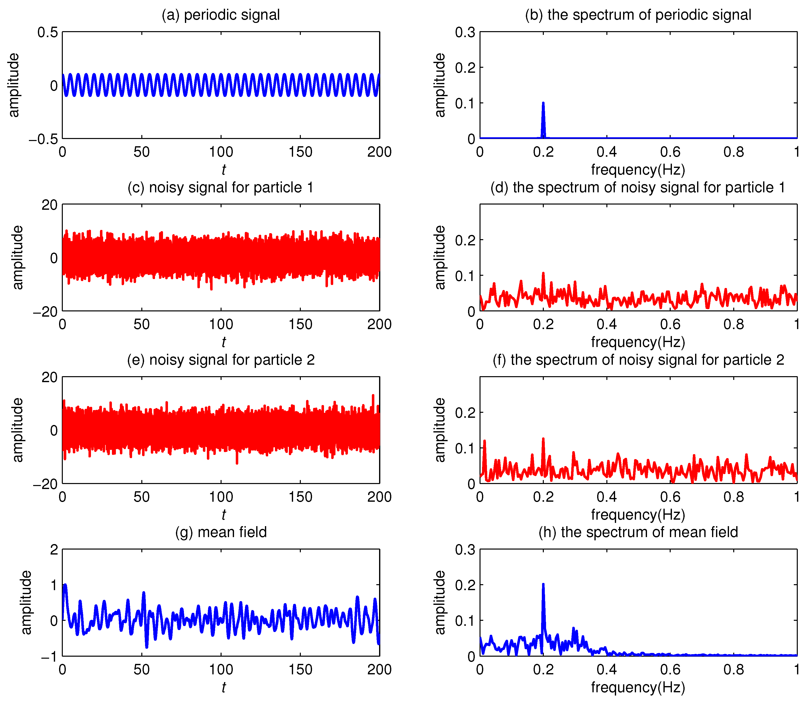
Finally, we provide a simple case to reveal the positive effect of the proposed system on weak signal detection. It is assumed that two coupled particles in the system are respectively driven by weak periodic signal f ( t ) = R cos ( 2 f t ) (with R = 0.1 , f = 0.2 ) and strong noise ζ 1 ( t ) and ζ 2 ( t ) (with D = 4 ). Figure 9a shows the time-domain waveform of weak signal f ( t ) , and the corresponding spectrum is depicted in Figure 9b, where a weak frequency feature can be clearly identified at the driving frequency f = 0.2 Hz. However, in the strong noise background, the weak signal is completely submerged in the time domain, as shown in Figure 9c,e. Moreover, the weak frequency feature cannot be identified in the spectra, as shown in Figure 9d,f. By regulating system parameters m = 1 , ω = 0.8 , γ = 1 , α = 0.4 , τ = 0.1 , ε = 1 , λ = 0.5 , and σ = 0.5 , we solve for system responses and obtain the mean field. It is observed from Figure 9g,h that the interferences are effectively suppressed in the time domain, and the component at f = 0.2 Hz can also be clearly identified. It reflects the positive effect of the proposed system on amplifying weak signals. Actually, this phenomenon has received widespread attention in mechanical fault diagnosis.

5. Conclusions

In this study, we propose two coupled time-delayed fractional oscillators with fluctuating frequencies to explore collective resonant behavior, with a specific focus on the influence of the coupling strength ε , time delay τ , and fractional order α . Employing the stochastic average method, we obtain complete synchronization between the average behaviors of the two particles and derive the analytical expression for the output amplitude gain G.
Based on the analytical results, we observe the collective parameter-induced SR phenomena in G ( ε ) , G ( τ ) , and G ( α ) . More concretely, time delay τ is conducive to the resonant region expansion of G ( ε ) . Obviously, increasing τ and decreasing α can enhance the intensity of the collective parameter-induced SR in G ( ε ) . In addition, ε has a similar complex influence on the collective parameter-induced SR in G ( τ ) and G ( α ) . We also observe that collective conventional SR phenomena take place in the coupled system. It is worth emphasizing that ε , α , and τ play a significant role in controlling the collective conventional SR behavior of G ( σ ) and G ( λ ) by facilitating the emergence and optimizing the intensity of collective resonant behavior. Subsequently, we corroborate the accuracy and validity of the analytical results through numerical simulation. Finally, we anticipate that the results of this study can furnish theoretical support for subsequent investigations for some potential applications.

Author Contributions

Conceptualization, L.L.; Methodology, H.W.; Software, M.H.; Formal analysis, M.H.; Investigation, M.H.; Writing—original draft, M.H.; Writing—review & editing, H.W. and L.L.; Supervision, L.L.; Funding acquisition, H.W. and L.L. All authors have read and agreed to the published version of the manuscript.

Funding

This study was funded by the National Natural Science Foundation of China (No. 72071019), the Natural Science Foundation of Fujian Province (No. 2020J01575), and the Innovation Fund of Fujian Agriculture and Forestry University (No. KFb22093XA).

Data Availability Statement

Data are contained within the article.

Conflicts of Interest

The authors declare that they have no conflicts of interest.

Appendix A. The Coefficients of Steady-State Output Amplitude

The coefficients of steady-state output amplitude In Equations (20) and (21), the related coefficients are listed as follows:
μ 1 = f 1 2 f 2 2 f 3 2 f 1 f 2 f 4 ε 2 f 3 f 1 f 5 + f 2 f 6 , μ 2 = f 1 2 f 2 2 f 4 2 f 1 f 2 f 3 ε 2 f 4 f 2 f 5 f 1 f 6 , μ 3 = σ 2 τ 2 Ω 2 + τ λ 1 f 1 f 3 f 2 f 4 f 5 τ Ω 2 τ λ f 1 f 4 + f 2 f 3 f 6 + f 7 μ 1 f 8 μ 2 , μ 4 = σ 2 τ 2 Ω 2 + τ λ 1 f 1 f 4 + f 2 f 3 f 6 + τ Ω 2 τ λ f 1 f 3 f 2 f 4 f 5 + f 7 μ 2 + f 8 μ 1 , f 1 = m λ 2 m Ω 2 + ω 2 τ ω 2 λ + ε + γ k 1 α cos ( α θ 1 ) , f 2 = 2 m λ Ω τ ω 2 Ω + γ k 1 α sin ( α θ 1 ) , f 3 = 4 m λ 2 m Ω 2 + ω 2 2 τ ω 2 λ + γ k 2 α cos ( α θ 2 ) , f 4 = 4 m λ Ω τ ω 2 Ω + γ k 2 α sin ( α θ 2 ) , f 5 = σ 2 1 3 τ λ + 2 τ 2 λ 2 τ 2 Ω 2 , f 6 = σ 2 τ Ω 3 τ λ 2 , f 7 = ω 2 m Ω 2 + γ Ω α cos π 2 α , f 8 = γ Ω α sin π 2 α τ ω 2 Ω , k 1 = Ω 2 + λ 2 , θ 1 = arctan Ω λ , k 2 = Ω 2 + 4 λ 2 , θ 2 = arctan Ω 2 λ .

References

  1. Benzi, R.; Sutera, A.; Vulpiani, A. The mechanism of stochastic resonance. J. Phys. A 1981, 14, L453–L457. [Google Scholar] [CrossRef]
  2. Gammaitoni, L.; Hänggi, P.; Jung, P.; Marchesoni, F. Stochastic resonance. Rev. Mod. Phys. 1998, 70, 223–287. [Google Scholar] [CrossRef]
  3. Mantegna, R.N.; Spagnolo, B. Stochastic resonance in a tunnel diode in the presence of white or coloured noise. Nuovo Cimento D 1995, 17, 873–881. [Google Scholar] [CrossRef]
  4. Lanzara, E.; Mantegna, R.N.; Spagnolo, B.; Zangara, R. Experimental study of a nonlinear system in the presence of noise: The stochastic resonance. Am. J. Phys. 1997, 65, 341–349. [Google Scholar] [CrossRef]
  5. Chang, C.; Tsong, T. Stochastic resonance in a biological motor under complex fluctuations. Phys. Rev. E 2004, 69, 021914. [Google Scholar] [CrossRef] [PubMed]
  6. Dylov, D.V.; Fleischer, J.W. Nonlinear self-filtering of noisy images via dynamical stochastic resonance. Nat. Photonics 2010, 4, 323–328. [Google Scholar] [CrossRef]
  7. Bejarano, D.E.J.; Saeki, K. Stochastic resonance in a pulse-type cell body model. Nonlinear Theory Its Appl. IEICE 2017, 8, 279–288. [Google Scholar] [CrossRef]
  8. Surazhevsky, I.A.; Demin, V.A.; Ilyasov, A.I.; Emelyanov, A.V.; Nikiruy, K.E.; Rylkov, V.V.; Shchanikov, S.A.; Bordanov, I.A.; Gerasimova, S.A.; Guseinov, D.V.; et al. Noise-assisted persistence and recovery of memory state in a memristive spiking neuromorphic network. Chaos Solitons Fractals 2021, 146, 110890. [Google Scholar] [CrossRef]
  9. Palabas, T.; Torres, J.J.; Perc, M.; Uzuntarla, M. Double stochastic resonance in neuronal dynamics due to astrocytes. Chaos Solitons Fractals 2023, 168, 113140. [Google Scholar] [CrossRef]
  10. Pikovsky, A.; Zaikin, A.; de la Casa, M.A. System size resonance in coupled noisy systems and in the Ising model. Phys. Rev. Lett. 2002, 88, 050601. [Google Scholar] [CrossRef]
  11. Casado-Pascual, J.; Gómez-Ordóñez, J.; Morillo, M.; Hänggi, P. Two-state theory of nonlinear stochastic resonance. Phys. Rev. Lett. 2003, 91, 210601. [Google Scholar] [CrossRef] [PubMed]
  12. Atsumi, Y.; Hata, S.; Nakao, H. Phase ordering in coupled noisy bistable systems on scale-free networks. Phys. Rev. E 2013, 88, 052806. [Google Scholar] [CrossRef] [PubMed]
  13. Gao, T.; Ai, B.; Zheng, Z.; Chen, J. The enhancement of current and efficiency in feedback coupled Brownian ratchets. J. Stat. Mech. 2016, 2016, 093204. [Google Scholar] [CrossRef]
  14. Berdichevsky, V.; Gitterman, M. Stochastic resonance in linear systems subject to multiplicative and additive noise. Phys. Rev. E 1999, 60, 1494. [Google Scholar] [CrossRef] [PubMed]
  15. Gitterman, M. Classical harmonic oscillator with multiplicative noise. Physica A 2005, 352, 309–334. [Google Scholar] [CrossRef]
  16. Li, J.; Han, Y. Phenomenon of stochastic resonance caused by multiplicative asymmetric dichotomous noise. Phys. Rev. E 2006, 74, 051115. [Google Scholar] [CrossRef] [PubMed]
  17. Zhang, L.; Zhong, S.C.; Peng, H.; Luo, M.K. Stochastic multi-resonance in a linear system driven by multiplicative polynomial dichotomous noise. Chin. Phys. Lett. 2011, 28, 090505. [Google Scholar] [CrossRef]
  18. Zhong, S.; Zhang, L. Noise effect on the signal transmission in an underdamped fractional coupled system. Nonlinear Dyn. 2020, 102, 2077–2102. [Google Scholar] [CrossRef]
  19. Vishwamittar; Batra, P.; Chopra, R. Stochastic resonance in two coupled fractional oscillators with potential and coupling parameters subjected to quadratic asymmetric dichotomous noise. Physica A 2021, 561, 125148. [Google Scholar] [CrossRef]
  20. Yu, T.; Zhang, L.; Ji, Y.; Lai, L. Stochastic resonance of two coupled fractional harmonic oscillators with fluctuating mass. Commun. Nonlinear Sci. Numer. Simul. 2019, 72, 26–38. [Google Scholar] [CrossRef]
  21. Lin, L.; He, M.; Wang, H. Collective resonant behaviors in two coupled fluctuating-mass oscillators with tempered Mittag-Leffler memory kernel. Chaos Solitons Fractals 2022, 154, 111641. [Google Scholar] [CrossRef]
  22. Liu, H.; Hu, G.; Zhang, Y.; Xiao, J. Frequency-dependent stochastic resonance in globally coupled systems. Commun. Theor. Phys. 2000, 33, 197–204. [Google Scholar]
  23. Zhong, S.; Lv, W.; Ma, H.; Zhang, L. Collective stochastic resonance behavior in the globally coupled fractional oscillator. Nonlinear Dyn. 2018, 94, 905–923. [Google Scholar] [CrossRef]
  24. Gómez-Ordóñez, J.; Casado, J.M.; Morillo, M. Arrays of noisy bistable elements with nearest neighbor coupling: Equilibrium and stochastic resonance. Eur. Phys. J. B 2011, 82, 179–187. [Google Scholar]
  25. Nicolis, C.; Nocolis, G. Coupling-enhanced stochastic resonance. Phys. Rev. E 2017, 96, 042214. [Google Scholar] [CrossRef]
  26. Beuter, A.; Bélair, J.; Labrie, C. Feedback and delays in neurological diseases: A modeling study using dynamical systems. Bull. Math. Biol. 1993, 55, 525–541. [Google Scholar] [CrossRef]
  27. Guillouzic, S.; L’Heureux, I.; Longtin, A. Small delay approximation of stochastic delay differential equations. Phys. Rev. E 1999, 59, 3970–3982. [Google Scholar] [CrossRef]
  28. Guillouzic, S.; L’Heureux, I.; Longtin, A. Rate processes in a delayed, stochastically driven, and overdamped system. Phys. Rev. E 2000, 61, 4906–4914. [Google Scholar] [CrossRef]
  29. Zhong, S.; Zhang, L.; Wang, H.; Ma, H.; Luo, M. Nonlinear effect of time delay on the generalized stochastic resonance in a fractional oscillator with multiplicative polynomial noise. Nonlinear Dyn. 2017, 89, 1327–1340. [Google Scholar] [CrossRef]
  30. Li, Z.; Han, S.; Wang, J.; Ren, X.; Zhang, C. Time-delayed feedback tristable stochastic resonance weak fault diagnosis method and its application. Shock Vib. 2019, 2019, 2097164. [Google Scholar] [CrossRef]
  31. Jin, Y.; Hu, H. Coherence and stochastic resonance in a delayed bistable system. Physica A 2007, 382, 423–429. [Google Scholar] [CrossRef]
  32. Bagley, R.L.; Torvik, P.J. Fractional calculus in the transient analysis of viscoelastically damped structures. AIAA J. 1985, 23, 918–925. [Google Scholar] [CrossRef]
  33. Narahari Achar, B.N.; Hanneken, J.W.; Enck, T.; Clarke, T. Dynamics of the fractional oscillator. Physica A 2001, 297, 361–367. [Google Scholar] [CrossRef]
  34. Ryabov Ya, E.; Puzenko, A. Damped oscillations in view of the fractional oscillator equation. Phys. Rev. E 2002, 66, 184201. [Google Scholar] [CrossRef]
  35. Kojabad, E.A.; Rezapour, S. Approximate solutions of a sum-type fractional integro-differential equation by using Chebyshev and Legendre polynomials. Adv. Differ. Equ. 2017, 2017, 351. [Google Scholar]
  36. Jafari, H.; Tuan, N.A.; Ganji, R.M. A new numerical scheme for solving pantograph type nonlinear fractional integro-differential equations. J. King Saud Univ. Sci. 2021, 33, 101185. [Google Scholar] [CrossRef]
  37. Mennouni, A.; Bougoffa, L.; Wazwaz, A.M. A new recursive scheme for solving a fractional differential equation of ray tracing through the crystalline lens. Opt. Quantum Electron. 2022, 54, 373. [Google Scholar] [CrossRef]
  38. Tian, Y.; Yu, T.; He, G.T.; Zhong, L.F.; Stanley, H.E. The resonance behavior in the fractional harmonic oscillator with time delay and fluctuating mass. Physica A 2020, 545, 123731. [Google Scholar] [CrossRef]
  39. You, P.; Lin, L.; Wang, H. Cooperative mechanism of generalized stochastic resonance in a time-delayed fractional oscillator with random fluctuations on both mass and damping. Chaos Solitons Fractals 2020, 135, 109789. [Google Scholar] [CrossRef]
  40. Tian, Y.; He, G.; Liu, Z.; Zhong, L.; Yang, X.; Stanley, H.E.; Tu, Z. The impact of memory effect on resonance behavior in a fractional oscillator with small time delay. Physica A 2021, 563, 125383. [Google Scholar] [CrossRef]
  41. Lin, L.; Lin, T.; Zhang, R.; Wang, H. Generalized stochastic resonance in a time-delay fractional oscillator with damping fluctuation and signal-modulated noise. Chaos Solitons Fractals 2023, 170, 113406. [Google Scholar] [CrossRef]
  42. He, M.Y.; Wang, H.Q.; Lin, L.F.; Zhong, S.C. Stochastic resonance of a time-delayed fractional oscillator with fluctuating frequency and signal-modulated noise. J. Sichuan Univ. (Nat. Sci. Ed.) 2024, 61, 011005. [Google Scholar]
  43. Kim, S.; Park, S.H.; Pyo, H.B. Stochastic resonance in coupled oscillator systems with time delay. Phys. Rev. Lett. 1999, 82, 1620–1623. [Google Scholar] [CrossRef]
  44. Banerjee, T.; Biswas, D. Synchronization in hyperchaotic time-delayed electronic oscillators coupled indirectly via a common environment. Nonlinear Dyn. 2013, 73, 2025–2048. [Google Scholar] [CrossRef]
  45. Zhang, G.; Wang, H.; Zhang, T. Stochastic resonance of coupled time-delayed system with fluctuation of mass and frequency and its application in bearing fault diagnosis. J. Cent. South Univ. 2021, 28, 2931–2946. [Google Scholar] [CrossRef]
  46. Yu, H.; Guo, X.; Wang, J.; Li, K.; Deng, B.; Wei, X.; Liu, C. Multiple stochastic resonances and oscillation transitions in cortical networks with time delay. IEEE Trans. Fuzzy Syst. 2020, 28, 39–46. [Google Scholar] [CrossRef]
  47. Kubo, R. The fluctuation-dissipation theorem. Rep. Prog. Phys. 1966, 29, 255–284. [Google Scholar] [CrossRef]
  48. Shapiro, V.E.; Loginov, V.M. “Formulae of differentiation” and their use for solving stochastic equations. Physica A 1978, 91, 563–574. [Google Scholar] [CrossRef]
  49. Li, J.L.; Xu, B.H. Parameter-induced stochastic resonance with a periodic signal. Chin. Phys. B 2006, 15, 2867–2871. [Google Scholar]
  50. Podlubny, I. Fractional differential equations. In Mathematics in Science and Engineering; Academic Press: San Diego, CA, USA, 1999. [Google Scholar]
Figure 1. Phase diagrams of G ( ε ) in the σ α plane: (a) without time delay τ = 0 ; (b) with time delay τ = 0.05 . Collective parameter-induced SR phenomena of G ( ε ) for different values of α and σ : (c) σ = 0.5 , τ = 0.05 ; (d) α = 0.5 , τ = 0.05 . The other parameters are set as m = 1 , ω = 1 , Ω = 2 , γ = 1 , and λ = 0.1 .
Fractalfract 08 00287 g001
Figure 2. (a) The nephogram of G ( ε , τ ) ; (b) G ( ε ) curves with different τ values. The other parameters are set as m = 1 , ω = 1 , Ω = 2 , γ = 1 , α = 0.5 , λ = 0.1 , and σ = 0.5 .
Fractalfract 08 00287 g002
Figure 3. Collective parameter-induced SR phenomena of G ( τ ) for different ε and α values: (a) α = 0.5 ; (b) ε = 1 . The other parameters are set as m = 1 , ω = 1.5 , Ω = 2 , γ = 0.5 , σ = 0.5 , and λ = 0.1 .
Fractalfract 08 00287 g003
Figure 4. Collective parameter-induced SR phenomena of G ( α ) for different ε and τ values: (a) τ = 0.1 ; (b) ε = 1 . The other parameters are set as m = 1 , ω = 1.5 , Ω = 2 , γ = 0.5 , σ = 0.5 , and λ = 0.1 .
Fractalfract 08 00287 g004
Figure 5. Collective conventional SR phenomena of G ( σ ) for different ε , τ and α values: (a) α = 0.4 , τ = 0.1 ; (b) α = 0.4 , ε = 1 ; (c) τ = 0.05 , ε = 1 . The other parameters are set as m = 1 , ω = 2 , Ω = 2 , γ = 0.5 , and λ = 0.1 .
Fractalfract 08 00287 g005
Figure 6. Collective conventional SR phenomena of G ( λ ) for different ε , τ , and α values: (a) α = 0.4 , τ = 0.2 ; (b) α = 0.4 , ε = 1 ; (c) τ = 0.2 , ε = 1 . The other parameters are set as m = 1 , ω = 1 , Ω = 2 , γ = 0.5 , and σ = 0.8 .
Fractalfract 08 00287 g006
Figure 7. (a) The noise realization of ξ 1 ( t ) and ξ 2 ( t ) ; (b) the trajectories of two coupled particles; (c) comparison between analytical and numerical results for x ( t ) . The other parameters are set as m = 1 , γ = 1 , ω = 1 , Ω = 0.4 π , ε = 1 , τ = 0.1 , α = 0.4 , σ = 0.5 , and λ = 0.5 .
Fractalfract 08 00287 g007
Figure 8. The comparison between the analytical and numerical results of G: (a) G ( ε ) with m = 1 , ω = 1 , Ω = 0.6 π , γ = 0.5 , α = 0.4 , τ = 0.1 , λ = 0.01 , and σ = 1 ; (b) G ( α ) with m = 1 , ω = 1 , Ω = 0.6 π , γ = 2 , τ = 0.1 , ε = 1 , λ = 0.5 , and σ = 0.1 ; (c) G ( τ ) with m = 1 , ω = 1.5 , Ω = 0.6 π , γ = 3 , α = 0.6 , ε = 2 , λ = 0.7 , and σ = 0.8 .
Fractalfract 08 00287 g008
Figure 9. (a) Weak periodic signal f ( t ) ; (b) the spectrum of the periodic signal; (c) noisy signal f ( t ) + ζ 1 ( t ) for particle 1; (d) the spectrum of the noisy signal for particle 1; (e) noisy signal f ( t ) + ζ 2 ( t ) for particle 2; (f) the spectrum of the noisy signal for particle 2; (g) mean field of the proposed system with m = 1 , ω = 0.8 , γ = 1 , α = 0.4 , τ = 0.1 , ε = 1 , λ = 0.5 , and σ = 0.5 ; (h) the spectrum of the mean field.
Fractalfract 08 00287 g009
Table 1. The absolute error between analytical and numerical results of G ( m ) .
m0.50.70.91.01.11.31.5
G N G A 0.00620.00300.00060.00170.00250.00000.0004
Disclaimer/Publisher’s Note: The statements, opinions and data contained in all publications are solely those of the individual author(s) and contributor(s) and not of MDPI and/or the editor(s). MDPI and/or the editor(s) disclaim responsibility for any injury to people or property resulting from any ideas, methods, instructions or products referred to in the content.