Article

Comparisons for Global Dynamics of a Geometrically Nonlinear Oscillator among Single-, Double- and Quadruple-Well Configurations

School of Mechanical Engineering, Shanghai Institute of Technology, Shanghai 201418, China
*
Author to whom correspondence should be addressed.
Fractal Fract. 2024, 8(4), 202; https://doi.org/10.3390/fractalfract8040202
Submission received: 12 February 2024 / Revised: 18 March 2024 / Accepted: 27 March 2024 / Published: 29 March 2024
(This article belongs to the Special Issue Fractional Diffusion, Multistability and Control in Complex Systems)

Abstract

:
This paper conducts a comparative analysis of the global dynamics of a harmonically excited oscillator with geometrical nonlinearities. Static analysis of the oscillatory system shows that adjusting the horizontal distance ratio from 1 to 0 can lead to single, double and quadruple well configurations successively. Intra-well and inter-well resonant responses are deduced analytically. Qualitative and quantitative results both reveal that the oscillator displays the stiffness–softening characteristic in cases of double and quadruple wells and the stiffness–hardening characteristic in the case of a single well. The initial-sensitive phenomenon jump is performed via fractal basins of attraction. Complex dynamical behaviors, including higher-order periodic responses and chaos, are also exhibited. The results demonstrate that the oscillator with a double or quadruple well configuration can achieve the inter-well response with large displacement, thus confirming its desirability in engineering applications of geometrically nonlinear oscillators.

1. Introduction

Oscillators with linear springs have obtained widespread concentration and exploration in the design of vibration energy harvesters (VEHs) [1,2] and vibration isolators [3,4,5] due to their capability of absorbing and storing mechanical vibration energy as potential energy. Based on the resonant mechanism, an oscillator with linear stiffness can work well in these engineering fields only if the frequency of the environmental excitation matches its resonant frequency, which limits the performance of the devices utilizing this type of oscillator. To overcome this disadvantage, elastic springs are set up obliquely, for instance, those in Figure 1 [6,7]. The geometric nonlinearities of springs correspond to the nonlinear restoring forces as well as the nonlinear stiffness of the oscillatory systems, which can induce the nonlinear resonance and construct the states of multi-stability by stiffness–softening or stiffness–hardening characteristics. For VEHs, the geometric configuration of linear springs in the oscillators can be effective in broadening the frequency band of the resonance, thereby showing effective qualities in improving the performance of VEHs [8,9,10]. The most commonly used oscillator is the smooth and discontinuous (SD) oscillator [11,12]. It consists of a lumped mass and a pair of symmetrically inclined springs, as can be seen in the primary structure of the VEH in Figure 1a. Whether its nonlinearity is smooth depends on the value of the smoothness parameter of the system. Another typical oscillator is comprised of a lumped mass and three hinged elastic springs (see the primary structure of Figure 1b), which is also 1-DOF. As these structures are simple and easily implemented, the optimal geometric configuration for nonlinear VEHs has received great attention in recent years [13,14]. Apart from this, in the design of nonlinear vibration isolators, oblique springs can help to add a negative stiffness mechanism along with the positive stiffness mechanism, thus inducing the quasi-zero stiffness (QZS) of the vibration isolators [15,16,17]. As QZS isolators can achieve a higher load capacity and wider isolation frequency band than traditional vibration isolators, the design and implementation of QZS isolators have gained much interest from both engineers and researchers [18,19].
For their engineering applications, the dynamics of oscillators with geometrical nonlinearities under variation in the structural parameters should be investigated intensively. Actually, the dynamics of these oscillators with geometric nonlinearities can be complex, even if they are single-degree-of-freedom systems. The geometric configuration of the springs causes irrational nonlinearity in the dynamic systems, hence causing difficulties in solving the analytical solutions of these systems. Theoretical and numerical approaches have been employed to investigate their nonlinear characteristics, including static bifurcations [20,21,22], approximative solutions [23,24,25], stochastic bifurcations [26] and global bifurcation analysis [27,28,29]. The SD oscillator subjected to harmonic excitation was found to possess the stiffness–hardening characteristics for a smooth parameter greater than one [23] but exhibited bistable potential wells and quad-stable responses for smooth parameters less than one [22,24]. Li et al. [25] discussed the stick-slip vibrations of a self-excited sliding SD oscillator from a global viewpoint. Yang and Cao [26] numerically studied stochastic bifurcations of the SD oscillator with additive and/or multiplicative bounded noises in terms of the evolution of the random attractor with variations in system parameters under stochastic excitation. Han et al. [27] investigated the global dynamics of a harmonic excited oscillator with three inclined springs and demonstrated that the oscillator could exhibit complex equilibrium bifurcations and significantly large vibrations, such as the inter-well chaotic responses for both smooth and discontinuous cases.
However, in previous works, the comparative analyses of oscillators with geometric nonlinearities under the adjustment of structural parameters have been insufficient, as the influence of the basins of attraction on the final outputs of the oscillators has seldom been taken into account. Multi-valued phenomena usually occur in these oscillators. In this circumstance, the adjustment of a structural parameter inducing the much larger amplitude response of an oscillator is not necessarily satisfactory because the probability of this response as the final response may be very low. Therefore, in this study, we focus on the impact of the system parameters on the multiple characteristics and final response of an archetype oscillator with geometric nonlinearities. This paper is organized as follows. In Section 2, a harmonically excited oscillator consisting of three springs is considered, the static bifurcations of which are then discussed. In Section 3, Section 4 and Section 5, the influences of its structural parameters on amplitude–frequency responses in the cases of single, double and quadruple potential wells are studied, respectively. Some novel findings are summarized thereafter.

2. Dynamical Model and Unperturbed Dynamics
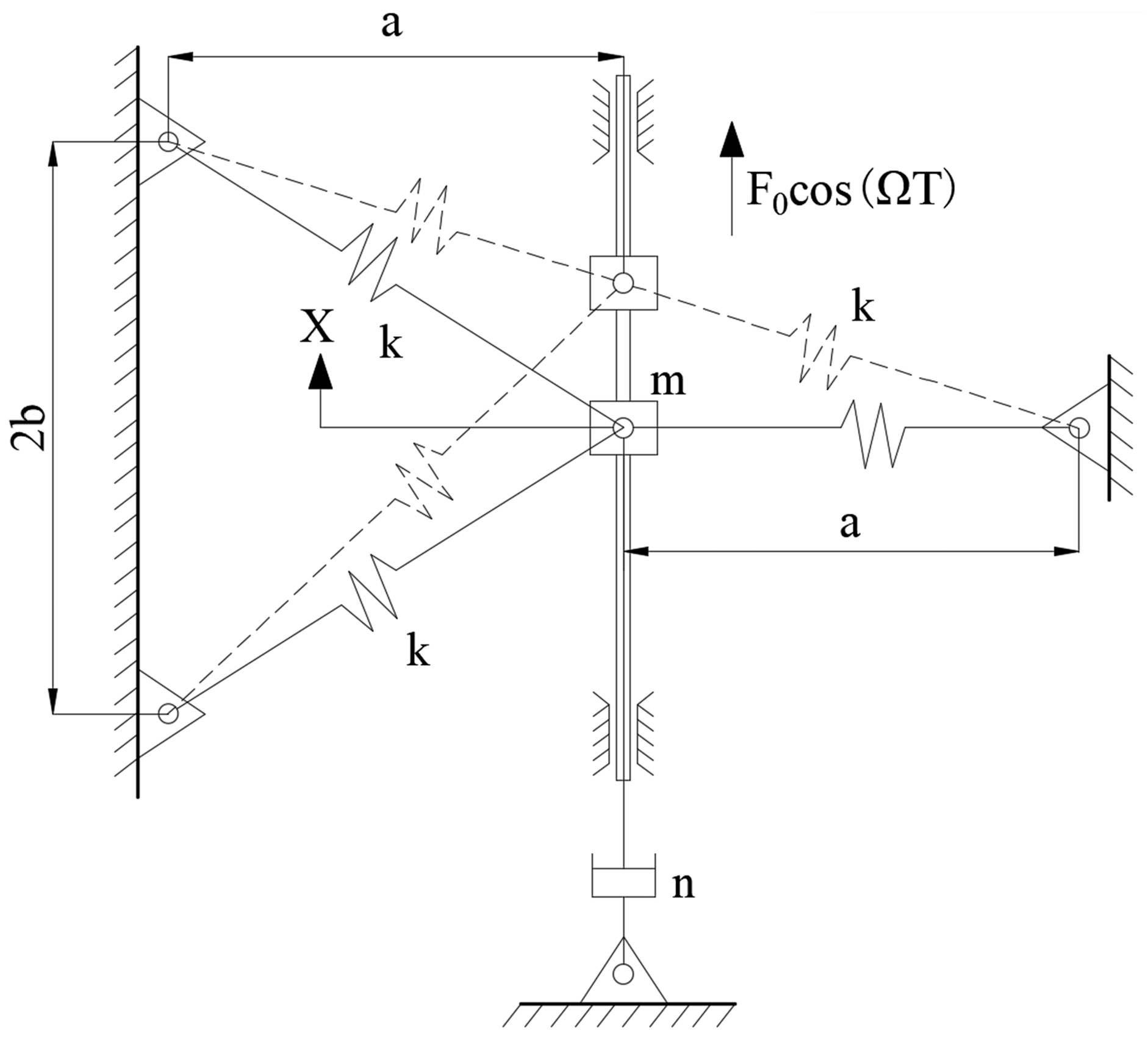
The oscillator under consideration consists of one collar and three elastic springs [27], as shown in Figure 2. It is a typical primary structure of vibration isolators [4,5] and VEHs [7,10]. Here, the collar with the mass m can move on the vertical slider with the linear damper n. Each spring is connected to the collar by a smooth pin on one end and is fixed to the base by a pin on the other end. Two springs on the left of the collar are initially inclined, while the spring on the right of the collar is initially horizontal. The stiffness and the initial length of the three springs are k and l, respectively. The structural parameters a and b represent the horizontal distance between the collar and each fixed pin and half the vertical distance between the two fixed pins connecting the tilted springs. Since the size of the collar is so small, it can be considered a lumped mass. Under harmonic excitation F 0 cos ( Ω T ) , its displacement, velocity and acceleration at time t are denoted by X , X and X , respectively. According to Newton’s Second Law, the dynamic system of the collar can be expressed as follows:
m X + n X + 2 k X ( 1 l X 2 + a 2 ) + k ( X + b ) ( 1 l ( X + b ) 2 + a 2 ) + k ( X b ) ( 1 l ( X b ) 2 + a 2 ) = F 0 cos ( Ω T ) .
The setting is as follows:
t = ω 0 T , α = a l , β = b l , f 0 = F 0 k l , ξ = n 2 m ω 0 2 , ω = Ω ω 0 , x = X l , ω 0 2 = k m ,
and the oscillatory system (1) is normalized as
x ¨ + 2 ξ x ˙ + x ( 1 1 x 2 + α 2 ) + ( x + β ) ( 1 1 ( x + β ) 2 + α 2 ) + ( x β ) ( 1 1 ( x β ) 2 + α 2 ) = f 0 cos ( ω t ) .
The adjustable geometrical parameters α and β represent horizontal and vertical distance ratios, respectively. Evidently, the above nondimensional system becomes discontinuous when α = 0 . In this study, both the distances a and b are assumed to be positive. Hence, we have α > 0 and β > 0 . And system (3) is a smooth and continuous system.
System (3) is perturbed by viscous damping and an external harmonic excitation. So, we can obtain its undisturbed system by letting the nondimensional damping coefficient ξ and the nondimensional excitation level f 0 be zero, as below:
x ˙ = y , y ˙ = [ x ( 1 1 x 2 + α 2 ) + ( x + β ) ( 1 1 ( x + β ) 2 + α 2 ) + ( x β ) ( 1 1 ( x β ) 2 + α 2 ) ] .
It is a Hamilton system with the Hamiltonian function H ( x ,   y ) and the potential energy function V ( x ) given by
H ( x ,   y ) = 1 2 y 2 + ( x 2 + α 2 1 ) 2 2 + ( ( x + β ) 2 + α 2 1 ) 2 2 + ( ( x β ) 2 + α 2 1 ) 2 2 , V ( x ) = 1 2 ( x 2 + α 2 1 ) 2 + 1 2 ( ( x + β ) 2 + α 2 1 ) 2 + 1 2 ( ( x β ) 2 + α 2 1 ) 2 .
By setting the right side of Equation (4) as zero, namely,
y = 0 , x ( 1 1 x 2 + α 2 ) + ( x + β ) ( 1 1 ( x + β ) 2 + α 2 ) + ( x β ) ( 1 1 ( x β ) 2 + α 2 ) = 0 ,
and we can determine the equilibria by solving the above equation. Evidently, the number and the positions of the equilibria depend on the values of the two geometric parameters α and β . Their corresponding structural parameters are distances a and b, respectively, meaning that the adjustment of the two distances may lead to static bifurcations of the system.
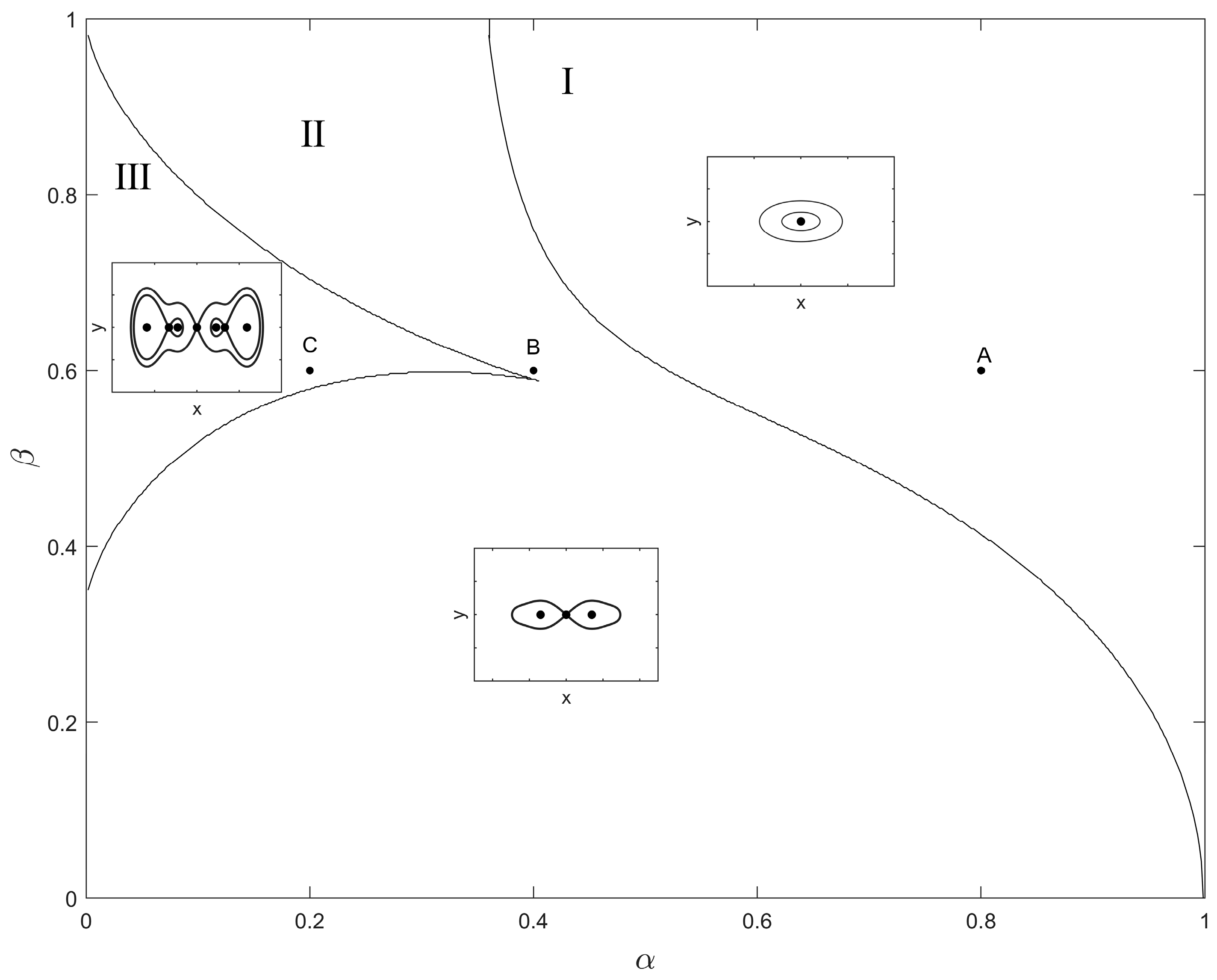
Considering the irrational nonlinear terms in Equation (4), it is hard for us to express x coordinates of the equilibria as the explicit functions of α and β . To tackle this issue, we employed the cell-mapping method to numerically classify the regions for the same numbers of equilibria in the plane α β composed by the 399 × 399 array of parameter points in the ranges 0 < α < 1 and 0 < β < 1 . Based upon Equations (5) and (6), the details for the static bifurcation diagrams of the unperturbed system (4) and the corresponding phase portraits are depicted in Figure 3. For the parameter points ( α , β ) in region I, there is only one equilibrium in the system (4), namely, the origin O(0, 0). As can be seen, the only potential well center O(0, 0) is surrounded by closed orbits. For the parameter point ( α , β ) in region II, there are three equilibria in the system (4), namely, the saddle point O(0, 0), and two nontrivial well centers surrounded by homoclinic orbits. When the parameter point ( α , β ) is selected from region III, there are three saddle points and four centers of potential wells in the unperturbed system. Without the loss of practical significance, we consider small viscous damping and a fixed value of half the nondimensional vertical distance of fixed supports β in the range (0, 1) by setting [28]
β = 0.6 , ξ = 0.01 .
Three parameter points A(0.8, 0.6), B(0.4, 0.6) and C(0.2, 0.6) are chosen from the regions I, II and III for the comparative investigation of the global dynamics of this oscillator in single, double and quadruple well configurations, respectively. In this way, the horizontal distance a can be taken as a control mechanism to vary the configurations. Under the three different values of α , the positions of equilibria are presented in Table 1.
Since the dimensionless damping coefficient is ξ > 0 , the centers of the unperturbed system (4) are stable in system (3) when f = 0. It means that these are fixed points to the system (3), so the initial conditions may be perturbed in the vicinity of these equilibriums. In the rest of the study, we consider both the influence of the harmonic excitation and the perturbation of initial states on the global dynamics of the system (3).
Figure 3. Static bifurcation diagram of the unperturbed system (4).
Fractalfract 08 00202 g003

3. Periodic Responses in the Case of Single Potential Well

To discuss the periodic responses in the vicinity of the only center, O (0, 0), the method of multiple scales (MMSs) is utilized. A new parameter ε satisfying 0 < ε < < 1 is introduced to rescale the parameters of the system (3) as follows:
ξ = ε ξ 0 , f = ε 2 f 0 .
Then, by expanding the irrationally and fractionally nonlinear terms of system (3) in Taylor’s series of x in the vicinity of x = 0 and neglecting higher-order-than-third terms of x, system (3) can be rewritten as
x ¨ + ω ¯ 2 x = 2 ε ξ 0 x ˙ + C 2 x 2 + C 3 x 3 + ε 2 f cos ( ω t ) .
where
ω ¯ = 3 1 α 2 α 2 ( α 2 + β 2 ) 3 2 ,   C 2 = 1 2 α 3 + 4 α 2 ( β 2 α 2 ) ( α 2 + β 2 ) 7 2 ,   C 3 = 3 8 α 5 + 3 α 2 ( α 4 12 α 2 β 2 + 8 β 4 ) 4 ( α 2 + β 2 ) 11 2 .
In the above equation, ω ¯ represents the resonant frequency of system (9). For α = 0.8 and β = 0.6 , one has ω ¯ = 0.686 , which is much less than the dimensionless natural frequency 1.
Suppose that system (9) is under the primary resonance and the detuning parameter σ = O ( 1 ) is introduced to the system, then one can rescale the dimensionless excitation frequency ω as follows:
ω 2 = ω ¯ 2 + ε σ .
In Equation (9), the dimensionless displacement x can be rescaled with different time scales and differential operators as
x = i = 1 n ε i x i , T i = ε i t , d d t = i = 0 n ε i D i , D i = T i ,
and the separate coefficients of ε , ε 2 , and ε 3 yields the following:
ε : D 0 2 x 1 + ω 2 x 1 = 0 ,
ε 2 : D 0 2 x 2 + ω 2 x 2 = σ x 1 2 D 0 D 1 x 1 2 ξ 0 D 0 x 1 + f cos ω t ,
and
ε 3 : D 0 3 x 3 + ω 2 x 3 = σ u 2 + C 2 x 1 3 2 D 0 D 1 x 2 D 1 2 x 1 2 D 0 D 2 x 1 2 ξ 0 D 0 x 2 2 ξ 0 D 1 x 1 .
The general solution of Equation (13) can be written as
x 1 = A ( T 1 , T 2 ) e i ω T + cc
where
A ( T 1 , T 2 ) = 1 2 a ( T 1 , T 2 ) e i ϕ ( T 1 , T 2 ) ,
where a ( T 1 , T 2 ) and φ are the amplitude and phase difference of the periodic solution x 1 , respectively. By substituting Equations (16) and (17) into Equation (14) and eliminating the secular terms there, one has
D 1 A = f i 4 ω σ A i 2 ω A ξ 0 , x 2 = 0 .
Then, substituting Equations (16)–(18) into Equation (15) and eliminating secular terms yields
D 2 A = f σ i 16 ω 3 A σ 2 i 8 ω 3 3 C 2 A 2 A ¯ i 2 ω + f ξ 0 8 ω 2 A ξ 0 2 i 2 ω .
According to Equation (12), the amplitude of the periodic solution x can be denoted by a ^ = ε a . Supposing A ˙ D 0 A + ε D 1 A + ε 2 D 2 A and substituting Equations (17)–(19) into it, one obtains
a ^ ˙ = ( ω ¯ 2 5 ω 2 ) sin β 8 ω 3 f 0 + ξ cos β 4 ω 2 f 0 a ^ ξ , a ^ ϕ ˙ = ( ω ¯ 2 5 ω 2 ) cos β 8 ω 2 f 0 ξ sin β 4 ω 2 f 0 a ^ ξ 2 2 ω 5 a ^ ω 8 + 3 a ^ ω ¯ 2 4 ω a ^ ω ¯ 4 8 ω 3 3 a ^ 3 C 2 8 ω .
Letting the right side of the above equation be zero and eliminating the triangulation functions of β based upon sin 2 β + cos 2 β = 1 yields
a ^ 2 [ 16 ξ 4 ω 4 + 104 ξ 2 ω 6 + 25 ω 8 12 ω ¯ 2 ( 4 ξ 2 ω 4 + 5 ω 6 ) + ω ¯ 4 ( 8 ξ 2 ω 2 + 46 ω 4 ) 12 ω 2 ω ¯ 6 + ω ¯ 8 ] + 6 ω 2 C 2 a ^ 4 ( 4 ξ 2 ω 2 + 5 ω 4 6 ω ¯ 2 ω 2 + ω ¯ 4 ) + 9 a ^ 6 ω 4 C 2 2 = [ 4 ξ 2 ω 2 + ( ω ¯ 2 5 ω 2 ) 2 ] f 0 2 .
The amplitude of the periodic solution can be solved for the above equation.
Based upon the Jacobian matrix of Equation (20), the characteristic equation of the periodic solution can be derived as follows:
λ 2 + 2 λ ξ + ζ = 0
where
ζ = 13 ξ 2 8 + ξ 4 4 ω 2 + ω ¯ 6 ( ω ¯ 2 12 ω 2 ) 64 ω 6 3 ω ¯ 2 16 ω 2 ( 4 ξ 2 + 5 ω 2 + 6 a ^ 2 C 2 ) + ω ¯ 4 32 ω 4 ( 4 ξ 2 + 23 ω 2 + 6 C 2 a ^ 2 ) + 1 64 ω 2 ( 25 ω 4 + 12 C 2 a ^ 2 ( 4 ξ 2 + 5 ω 2 ) + 27 a ^ 4 C 2 2 ) .
Since both ξ and ζ are real numbers, there is no purely imaginary roots in Equation (22). It indicates that the stability of the periodic solution can be changed only if λ = 0 in Equation (23), namely, ζ = 0 . Hence, the stability switch of the resonant solution can be ascribed to the saddle-node bifurcation.
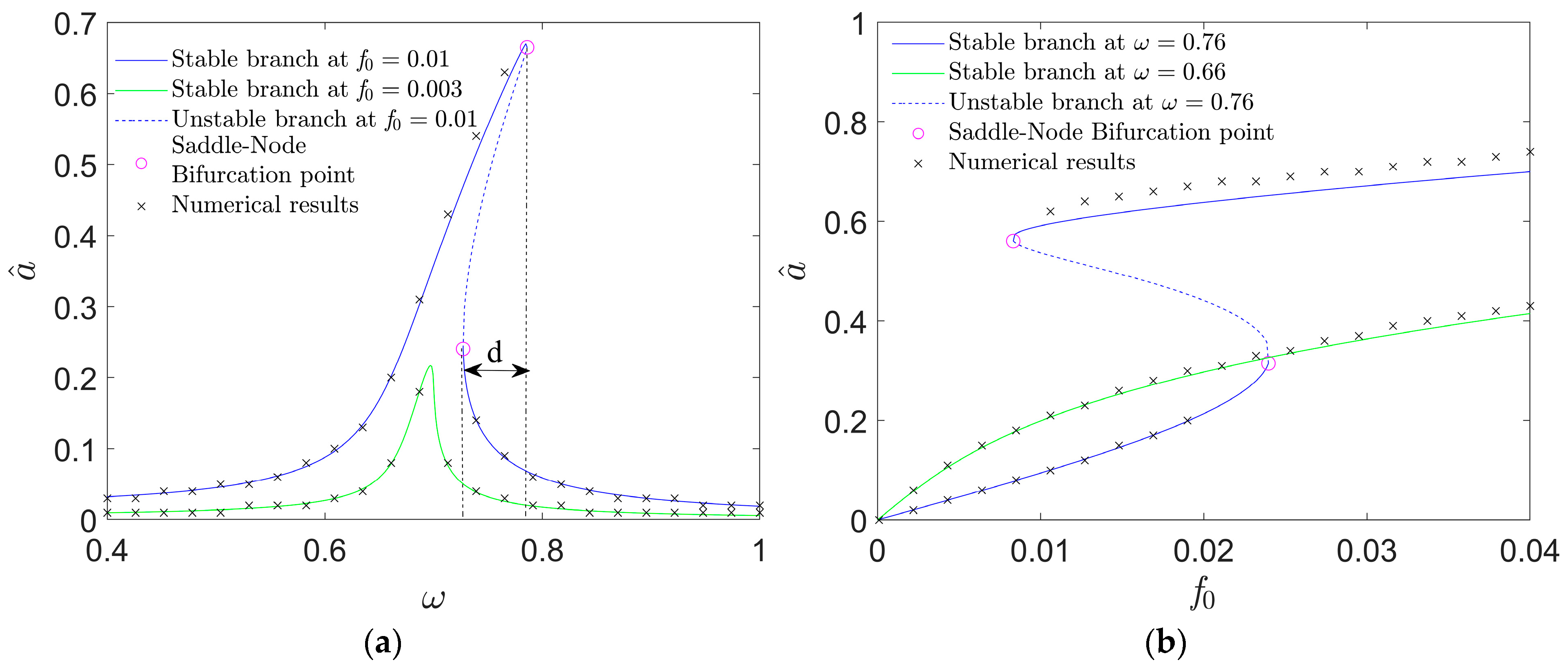
Based upon Equations (21)–(23), Figure 4 can be plotted to depict the amplitude variations in the resonant responses with the excitation. Via the fourth Runge–Kutta approach and the software MATLAB2018a, numerical results are provided (see the cross signs in Figure 4). As they match the analytical solution branches well, the accuracy of the prediction is validated.
As shown in Figure 4a, the steady solution branch is continuous at f 0 = 0.003 , but bends to the right at f 0 = 0.01 , meaning that the stiffness–hardening characteristic yields bistable states. There is a frequency band with the bandwidth d for f 0 = 0.01 . When ω is within the frequency band, there are bistable responses. Since the higher-amplitude resonant response corresponds to a much larger displacement that may be more favorable in engineering applications such as energy harvesting and vibration isolation, this frequency band is useful. The phenomenon of jumping between two responses can also be observed when the initial states of the oscillatory system’s change.
In Figure 4b, two values of the excitation frequency are chosen within and outside of the frequency band, namely ω = 0.76 and ω = 0.66 . Solution branches under the two frequencies are presented. It can be observed that when f 0 is small, the amplitude of the resonant response at ω = 0.66 is higher than the one at ω = 0.76 . Under a higher excitation level, the higher-amplitude response branch at ω = 0.76 is clearly above the resonant response branch at ω = 0.66 .
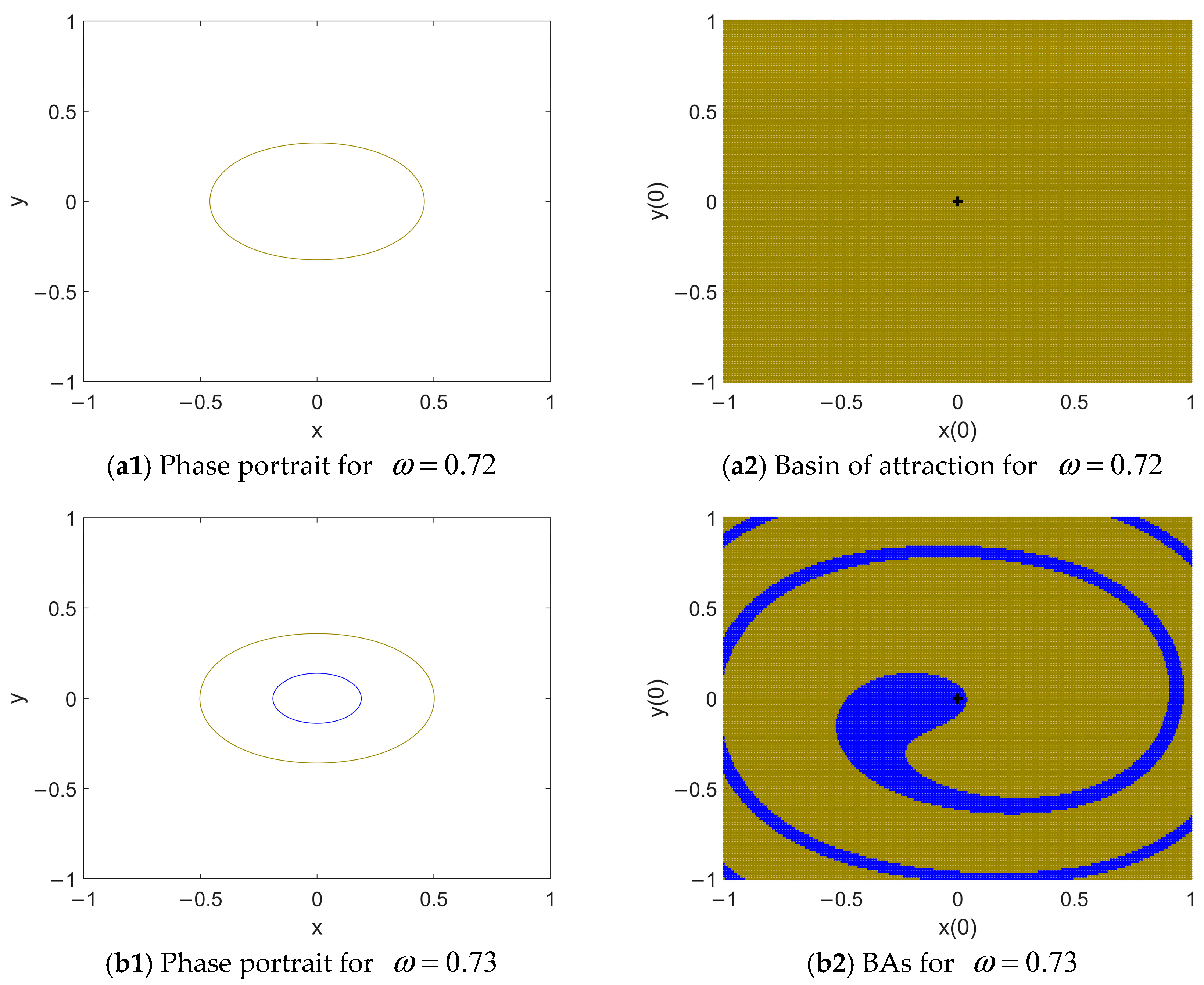
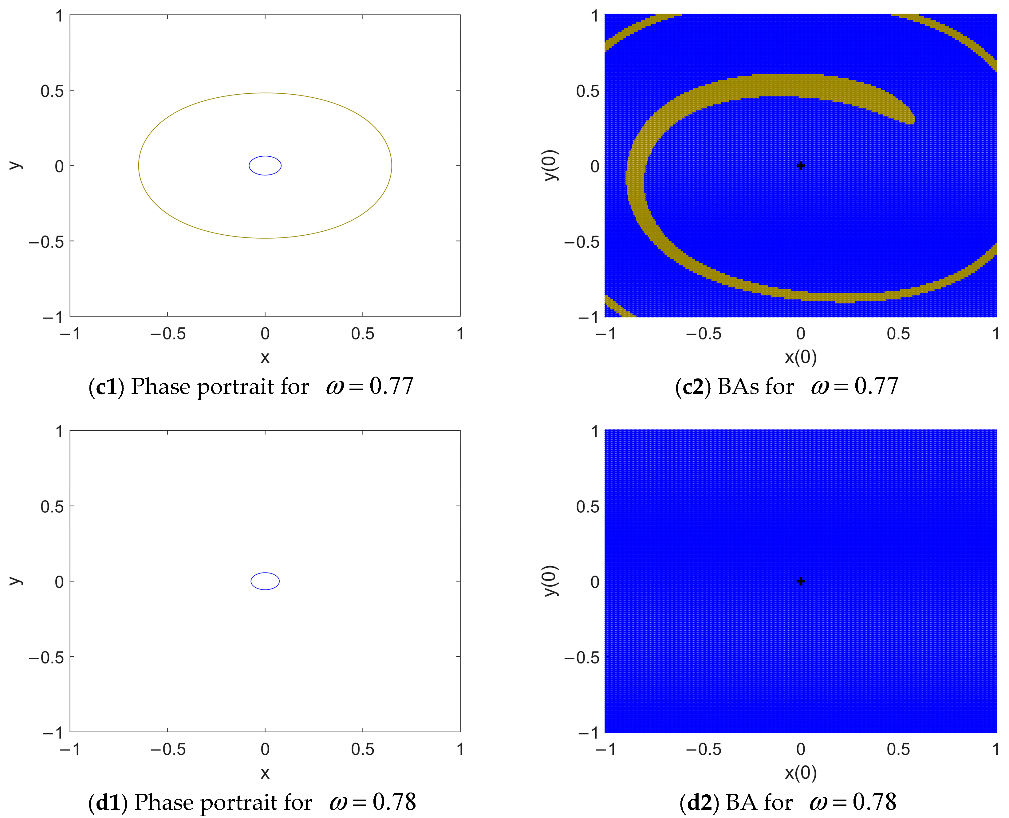
In the circumstances of multi-stability, we consider the impact of the perturbation of the initial states on the final response of system (3). Hence, we classify the basins of attraction (BA) of the responses via the cell-mapping method. The initial condition plane x ( 0 ) y ( 0 ) is set within the sufficiently large region 1 x ( 0 ) 1 ,   1 y ( 0 ) 1 consisting of the 301 × 151 array of initial condition points. The sequences of the responses and their BAs with the increase in ω are presented in Figure 5 where f 0 = 0.01 . Figure 5 consists of two columns where the left and right columns depict the phase maps and BAs of the coexisting responses, respectively. Each response and its BA are marked in the same color.
In Figure 5(a1), there is only one periodic attractor. So, it is globally attractive, as shown in the BA of Figure 5(a2). A little increase in ω leads to the occurrence of a new attractor with a much lower amplitude (see the dark yellow portrait in Figure 5(b1)). Even though its BA is very small, the vicinity of O(0, 0) (see the black cross in Figure 5(b2)) is eroded by its BA. Since most of the time, the initial conditions of the system are within the neighborhood of the fixed point, the lower-amplitude response has a high probability of being the final response. When ω is increased to 0.77, the higher-amplitude response becomes the hidden attractor [30] as its BA is beyond the vicinity of O(0, 0) (see Figure 5(c2)). A further increase in ω leads to the vanishing of the higher-amplitude response and the global attraction of the lower-amplitude one, as shown in Figure 5(d1,d2).

4. Periodic Responses in the Case of Double Potential Wells

4.1. Intra-Well Resonant Responses

In the case of the double potential well of the system, similar to the last section, MMS is also applied. The only difference is that the intra-well periodic solutions here are around the non-trivial centers C ± ( ± x c , 0 ) . Therefore, it is supposed that
x = ± x c + u .
By substituting Equation (24) and rescaled parameter (8) into system (3), expanding the fractional terms in Taylor’s series of u in the vicinity of u = 0 and neglecting the higher-order-than-third terms of u, one can rewrite system (3) as
u ¨ + ω ^ 2 u = 2 ε ξ 0 u ˙ + Q 2 u 2 + Q 3 u 3 + ε 2 f cos ( ω t )
where
ω ^ = 3 α 2 ( α 2 + x c 2 ) 3 2 α 2 ( ( β x c ) 2 + α 2 ) 3 2 α 2 ( ( β + x c ) 2 + α 2 ) 3 2 , Q 2 = 3 α 2 x c 2 ( α 2 + x c 2 ) 5 2 + 3 α 2 ( β x c ) 2 ( ( β x c ) 2 + α 2 ) 5 2 3 α 2 ( β + x c ) 2 ( ( β + x c ) 2 + α 2 ) 5 2 , Q 3 = α 2 ( α 2 4 x c 2 ) 2 ( α 2 + x c 2 ) 7 2 + α 2 ( 4 ( β + x c ) 2 α 2 ) 2 ( ( β + x c ) 2 + α 2 ) 7 2 + α 2 ( 4 ( β x c ) 2 α 2 ) 2 ( ( β x c ) 2 + α 2 ) 7 2 .
It can be calculated that the resonant frequency ω ^ in this mode is 0.513 for α = 0.4 and β = 0.6 .
In system (25), the frequency ω and the displacement u can be rescaled as follows:
ω = ω ^ + ε σ , u = i = 1 n ε i u i ( T 0 , T 1 , T 2 ) ,
and by applying MMS to the third order of ε , one can express the resonant solutions as
x = ± x c + a ˜ cos ( φ ˜ + ω T 0 )
where a ˜ and φ ˜ are the amplitude and phase difference of the resonant solutions, respectively, given by
a ˜ ˙ = a ˜ ξ + ( ω ^ 3 ω ) f 0 sin φ ˜ + ξ f 0 cos φ ˜ 4 ω 2 , a ˜ φ ˜ ˙ = a ˜ ( ω ^ ω ξ 2 2 ω ) a ˜ 3 24 ω 3 ( 10 Q 2 2 + 9 ω 2 Q 3 ) + ( ω ^ 3 ω ) f 0 cos φ ˜ ξ f 0 sin φ ˜ 4 ω 2 .
Letting the right side of the above equation be zero and eliminating the triangulation functions of φ ˜ yields
( 10 Q 2 2 + 9 ω 2 Q 3 ) 2 a ˜ 6 36 ω 2 + 2 3 ( 10 Q 2 2 + 9 ω 2 Q 3 ) ( ξ 2 + 2 ω 2 2 ω ω ^ ) a ˜ 4 + 4 ω 2 a ˜ 2 ( ξ 2 ( ξ 2 + 8 ω 2 4 ω ω ^ ) + 4 ω 2 ( ω ω ^ ) 2 ) = ( ξ 2 + ( 3 ω ω ^ ) 2 ) f 0 2 .
By solving Equation (30), one can determine the amplitude of the resonant solution. Based on the Jacobian matrix of Equation (29), the corresponding characteristic equation can be obtained, as shown below
λ 2 + 2 λ ξ + ( ω ω ^ ) 2 + ξ 2 4 ω 2 ( ξ 2 + 8 ω 2 4 ω ω ^ ) + a ^ 4 ( 10 Q 2 2 + 9 ω 2 Q 3 ) 2 192 ω 6 + a ^ 2 ( 10 Q 2 2 + 9 ω 2 Q 3 ) ( ξ 2 2 ω ω ^ + 2 ω 2 ) 12 ω 4 = 0 .
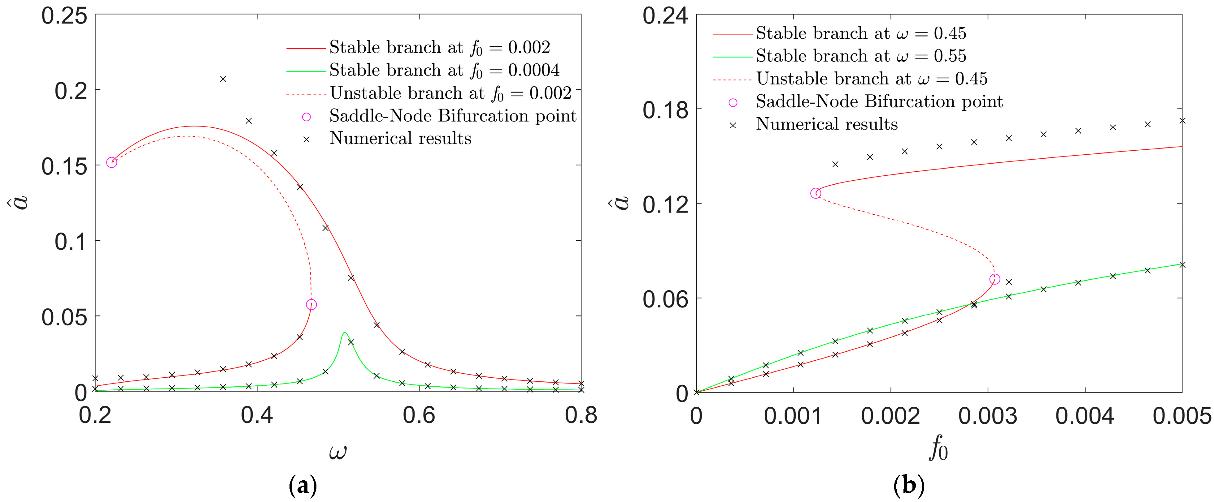
Similar to Equation (22), there are no purely imaginary solutions in Equation (31). Therefore, the stability of the resonant solution can be switched at the saddle-node bifurcation points of the intra-well periodic solution. Given that α = 0.4 and β = 0.6 , the amplitude variation in the resonant solution with the dimensionless excitation is presented in Figure 6.
It follows from Figure 6a that with the increase in ω , the solution branch for f 0 = 0.002 bends to the left, displaying the stiffness–softening characteristic and bistable periodic responses within each potential well, which is totally different from the case of the single potential well. When ω exceeds the horizontal coordinate of the right SN bifurcation point, the higher-amplitude periodic solution is the only attractor within each potential well. For example, given f 0 = 0.002 , two intra-well resonant responses coexist at ω = 0.45 , while there is only one intra-well response around C ± at ω = 0.55 . In Figure 6b, the comparison between the solution branches in two different colors illustrates that a larger-displacement intra-well response can be achieved when ω is within the bistable-response frequency band. Note that the qualitative results in Figure 6 are in good agreement with the quantitative ones, validating the accuracy of the prediction. The discrepancy under a very low excitation frequency can be due to the limitation of MMS. As calculated, ω ^ = 0.513 . When ω is beyond the vicinity of ω ^ , and the amplitude of the resonant solution is high, Equation (27) cannot be satisfied, and the analytical prediction cannot work very well.

4.2. Inter-Well Periodic Solutions in the Case of Double Potential Wells

In the case of double potential wells, the system may also have a periodic response beyond the vicinity of the two non-trivial centers, namely the so-called inter-well response, whose amplitude is definitely higher than the intra-well ones. Unlike the intra-well resonant responses, MMS is unsuitable for the analysis of the inter-well response. Instead, the averaging method can be employed.
The amplitude A and the phase difference θ of the inter-well periodic solution are introduced to rewrite the inter-well periodic of the solution, as follows:
x = A cos ( ω t + θ ) , x ˙ = A ω sin ( ω t + θ ) .
Accordingly, system (3) can be expressed by
A ˙ cos ( ω t + θ ) A θ ˙ sin ( ω t + θ ) = 0 , A ˙ sin ( ω t + θ ) + A θ ˙ cos ( ω t + θ ) = 1 ω H ( A , θ , t ) ,
where
H ( A , θ , t ) = A ω 2 cos ( ω t + θ ) + A cos ( ω t + θ ) ( 1 1 α 2 + ( A cos ( ω t + θ ) ) 2 ) + ( A cos ( ω t + θ ) β ) ( 1 1 α 2 + ( A cos ( ω t + θ ) β ) 2 ) + ( A cos ( ω t + θ ) + β ) ( 1 1 α 2 + ( A cos ( ω t + θ ) + β ) 2 ) 2 A ξ ω sin ( ω t + θ ) f 0 cos ( ω t ) .
Based upon Equations (32)–(34), the two slowly varying parameters A and θ can be written as
A ˙ = 1 ω H ( A , ϕ ) sin ϕ , θ ˙ = 1 A ω H ( A , ϕ ) cos ϕ
where ϕ = ω t + θ . Integrating the above equation over a whole time period [ 0 ,   2 π ω ] , letting its right side be zero, and eliminating trigonometric terms, one can obtain
f 0 2 4 ω 2 = A 2 ξ 2 + ( S 1 + S 2 + S 3 A ω 2 ) 2 .
Here,
S 1 = A 2 π ω 0 2 π cos 2 ϕ ( 1 1 α 2 + A 2 cos 2 ϕ ) d ϕ , S 2 = 1 2 π ω 0 2 π cos ϕ ( A cos ϕ β ) ( 1 1 α 2 + ( A cos ϕ β ) 2 ) d ϕ , S 3 = 1 2 π ω 0 2 π cos ϕ ( A cos ϕ + β ) ( 1 1 α 2 + ( A cos ϕ + β ) 2 ) d ϕ .
The stability of the inter-well solution is decided by the real parts of the solution of its characteristic equation:
λ 2 + 2 λ ξ + ξ 2 + 1 4 A 2 ( ω A 2 S 1 2 S 2 2 S 3 ) ( ω 2 B 1 2 B 2 2 B 3 ) = 0
where
B 1 = 1 2 π ω 0 2 π A 2 cos 4 ϕ ( α 2 + A 2 cos 2 ϕ ) 3 2 + cos 2 ϕ ( 1 1 ( α 2 + A 2 cos 2 ϕ ) ) d ϕ , B 2 = 1 2 π ω 0 2 π cos 2 ϕ ( A cos ϕ β ) 2 ( α 2 + ( A cos ϕ β ) 2 ) 3 2 + cos 2 ϕ ( 1 1 α 2 + ( A cos ϕ β ) 2 ) d ϕ , B 3 = 1 2 π ω 0 2 π cos 2 ϕ ( A cos ϕ + β ) 2 ( α 2 + ( A cos ϕ + β ) 2 ) 3 2 + cos 2 ϕ ( 1 1 α 2 + ( A cos ϕ + β ) 2 ) d ϕ .
If the solution to Equation (38) has a positive real part, then the corresponding inter-well periodic solution is unstable. Since there is no purely imaginary solution in Equation (38) either, the stability of the inter-well solution changes only if λ = 0 , showing that the stability switch of the inter-well solution is also led by its SN bifurcation. The inter-well periodic solution is stable only if
ξ 2 + 1 4 A 2 ( ω A 2 S 1 2 S 2 2 S 3 ) ( ω 2 B 1 2 B 2 2 B 3 ) > 0 , A > x e ,
where x e is the nontrivial solution of H ( x , 0 ) = H ( 0 , 0 ) . It means that the amplitude of the inter-well solution should exceed the maximum horizontal coordinate of the homoclinic orbits of the unperturbed system.
For α = 0.4 and β = 0.6 , given the value of ω in the frequency band for bistable responses, for instance, ω = 0.45 , the variation in the inter-well solution branch with f 0 can be observed in Figure 7, where the theoretical results match the quantitative ones well, showing the validity of the analysis via the average method. It can be concluded from Figure 7 that with the increase in the excitation level, the inter-well’s periodic response coexists with the intra-well ones.

4.3. Coexisting Responses and Their Basins of Attraction

To observe the evolution of these coexisting responses and their BAs with the excitation level f 0 , we depict Figure 8.
To begin with this, for f 0 = 0.0012 , around each well center, there is an intra-well periodic response whose amplitude is very low (see Figure 8(a1)). The BA of each response has a smooth boundary and is continuous in the vicinity of the corresponding nontrivial center (see Figure 8(a2)), showing the local attraction of each response.
When f 0 is increased a little to 0.0014, two new intra-well responses with much higher amplitudes appear, coexisting with the former ones (see the red and black portraits in Figure 8(b1)). According to their BAs in Figure 8(b2), they are hidden attractors, implying that for initial conditions disturbed from the fixed point C ± , the final response of system (3) tends to be a lower-amplitude response rather than a higher-amplitude one.
As f 0 exceeds 0.0032, the BAs of the two lower-amplitude responses are so small that the lower-amplitude periodic responses become rare attractors [31] (see Figure 8(c1,c2)). Then, a small increase in f 0 leads to their disappearance, as can be seen in Figure 8(d1,d2).
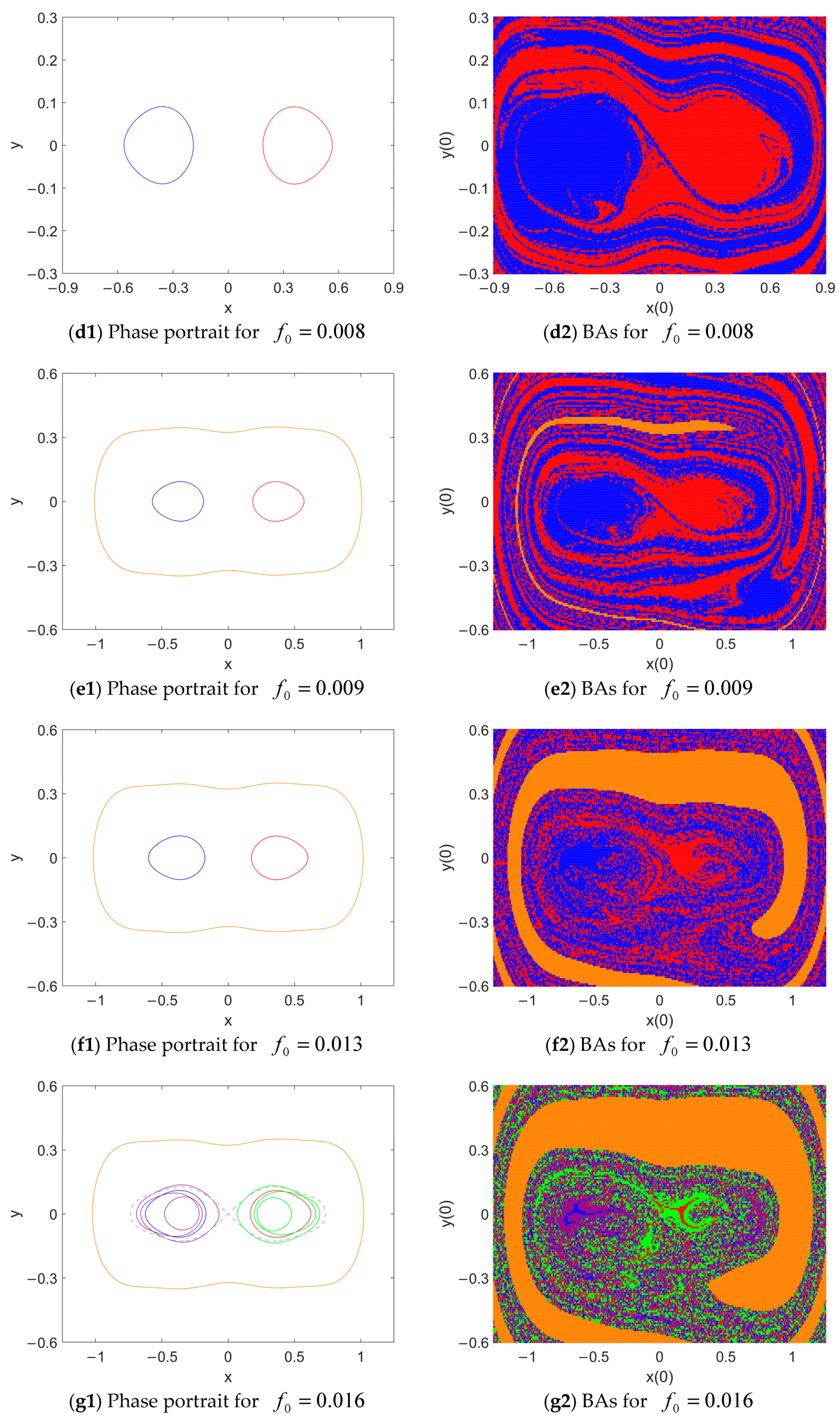
When f 0 = 0.009 , an inter-well periodic attractor appears (see the orange closed phase map in Figure 8(e1)). Since the initial plane | x ( 0 ) | 0.9 ,   | y ( 0 ) | 0.3 is not large enough, we expanded the initial-condition plane to | x ( 0 ) | 1.25 ,   | y ( 0 ) | 0.6 to better observe these attractors and their BAs. The new attractor is a hidden attractor as its BA is far beyond the vicinity of the centers C ± and O(0, 0) (see Figure 8(e2)). Simultaneously, the fractal characteristic of the BAs of the two intra-well attractors becomes more and more visible, especially in the area beyond the vicinity of C ± .
As f 0 continues to increase, the BA of the inter-well periodic response is enlarged with a smooth boundary (see Figure 8(f2,g2,h2). Coexisting with the symmetric intra-well periodic attractors, complex attractors such as intra-well period-3 attractors (see Figure 8(g1)), chaos (see Figure 8(h1,h3,h4)) and the inter-well period-4 attractor (see Figure 8(i1)) occur successively. Their BAs are segmented into fractal and discrete pieces, illustrating how all the complex attractors have severely fractal BAs. Therefore, when the initial conditions are disturbed from the fixed point C ± , it is hard to determine the final dynamics of the system (3). Unlike the chaotic response, it is another type of initial-sensitive phenomenon.
Finally, when f 0 grows to 0.04, the inter-well periodic response becomes the only attractor of the system (3) whose BA occupies the whole initial-state plane (see Figure 8(j1,j2)), showing its global attraction and integrity.

5. Periodic Responses in the Case of Quadruple Potential Wells

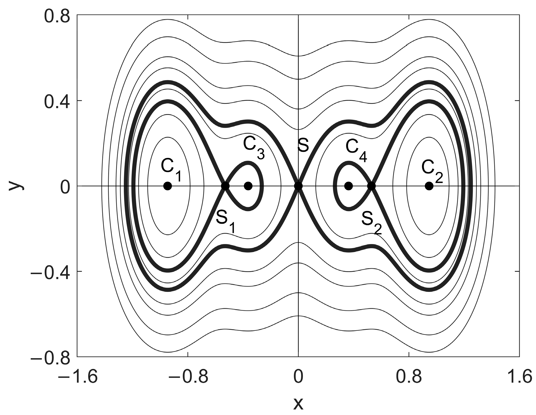
Considering the case of quadruple potential wells, we set α = 0.2 . Based on Equation (5), the unperturbed orbits are illustrated in Figure 9. The positions of four potential well centers, as well as three saddle points, are provided in Table 1. In this section, we concentrate on the analyses of the intra-well periodic responses and numerical simulations concerning the coexisting responses and their BAs in the case of quadruple wells.

5.1. Resonant Responses around the Centers

Since the four well centers are all nontrivial, the intra-well resonant solutions in the vicinity of the centers can be obtained via the same analytical method in Section 4.1. By substituting the horizontal coordinates of the centers C 1 , 2 and C 3 , 4 , namely, x c = 0.945 and x c = 0.365 into Equation (25) successively, the resonant frequencies in the vicinity of these centers C 1 , 2 and C 3 , 4 are calculated as ω ^ 1 = 1.521 and ω ^ 2 = 1.022 , respectively. According to Equation (27), the resonant solutions around C 1 , 2 and C 3 , 4 can be written as
x = ± x c 1 + a 1 cos ( φ 1 + ω T 0 ) , x = ± x c 2 + a 2 cos ( φ 2 + ω T 0 ) ,
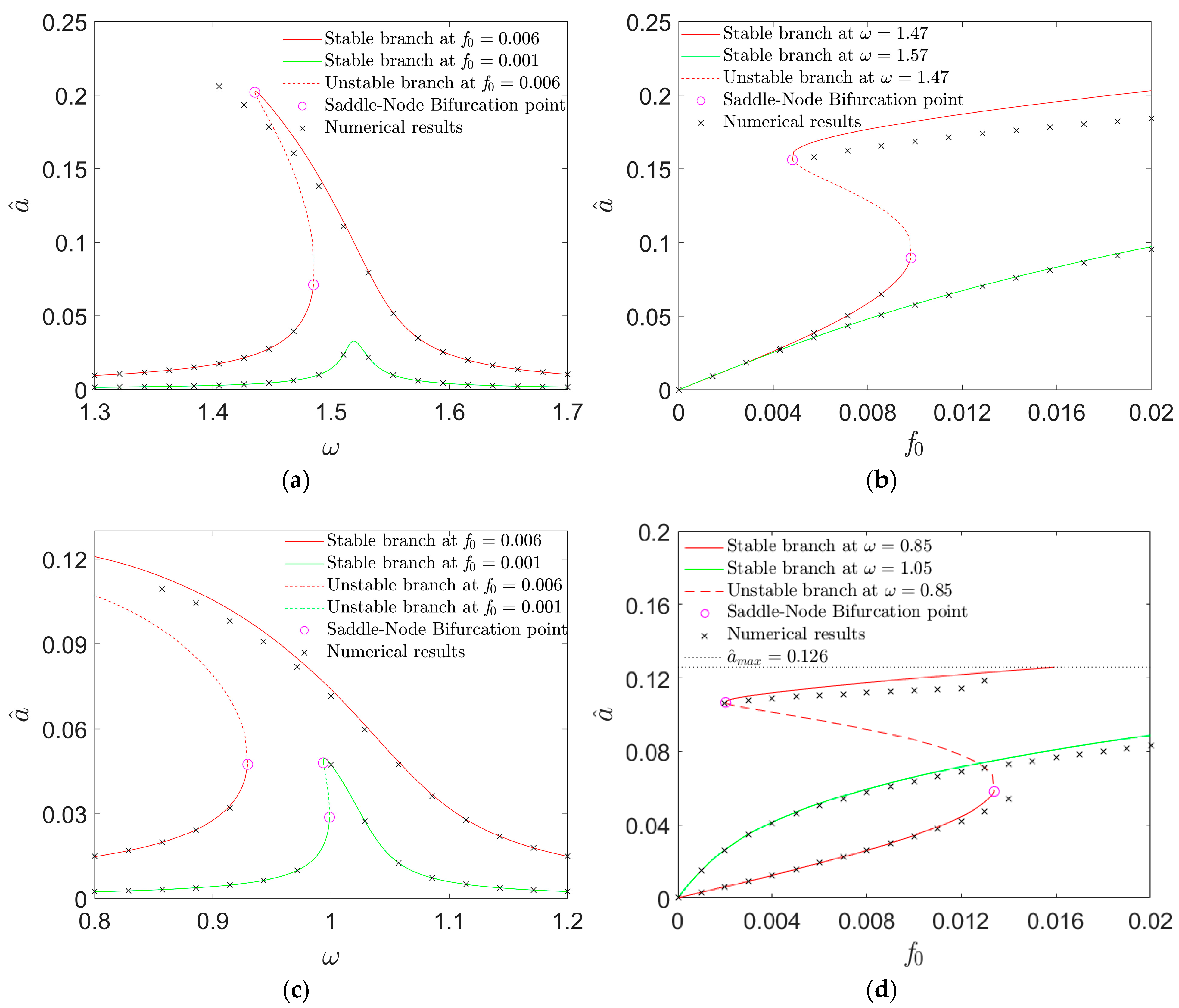
where a 1 and a 2 are the amplitudes of the responses around C 1 , 2 and C 3 , 4 , respectively. By following Equations (30) and (31), the variation in the response amplitude branches around C 1 , 2 and C 3 , 4 with the dimensionless excitation is presented in Figure 10.
It is clear in Figure 10a,c that with the rise in ω , the solution branches for f 0 = 0.006 bend to the left (see the red curves), showing the stiffness–softening characteristics, similar to the intra-well responses in the case of double potential wells. For the value of ω within or beyond each frequency band for bistable responses, the dynamics are totally different. For instance, given f 0 = 0.006 , two resonant responses coexist in the vicinity of C 1 , 2 at ω = 1.47 while there is only one intra-well resonant response around C 1 , 2 at ω = 1.57 . Comparing the solution branches in different colors in Figure 10b, one observes that with the increase in f 0 , the value of ω given within the bistable-response frequency band can provide a larger displacement response. A similar situation can be found in the vicinity of C 3 , 4 , as depicted in the solution branches at ω = 1.05 and ω = 0.85 in Figure 10d.
As can be seen in Figure 9, the potential wells around C 1 , 2 are significantly larger than the ones around C 3 , 4 . It can also be observed in Figure 10 that the peak amplitude of the intra-well response around C 1 , 2 is far higher than the one around C 3 , 4 . Accordingly, to achieve a larger-displacement resonant response, it is better to oscillate under the primary resonance in the vicinity of C 1 , 2 . In other words, the excitation frequency ω in the vicinity of ω ^ 1 can help to achieve a much higher-amplitude response. In the following discussion, the case of ω near ω ^ 1 is focused on.

5.2. Coexisting Attractors and Their Basins of Attraction

Given that α = 0.2 and ω = 1.47 , the evolution of the responses and their BAs with the rise in f 0 is illustrated in Figure 11. Here, the BAs of the responses are classified in the initial-state plane | x ( 0 ) | 1.6 , | y ( 0 ) | 0.8 . For each response, its phase map and BA are marked in the same color. For f 0 = 0 , according to the analysis, the four well centers of the unperturbed system are fixed points. Therefore, the initial state of system (3) is disturbed from these positions.
For f 0 = 0.004 , around each potential-well center, there is an attractor whose BA occupies the vicinity of the center (see Figure 11(a1,a2)). Evidently, all the responses are locally attractive. As predicted, the periodic responses around C 1 , 2 possess a higher amplitude.
As f 0 increases to 0.005 (see Figure 11(b1,b2)), a pair of new attractors with a higher amplitude appear in the vicinity of C 1 , 2 , coexisting with the former ones. And their BAs are beyond the neighborhood of C 1 , 2 , implying that they are hidden attractors.
When f 0 continues to grow, one can find the rise in the amplitudes of all the attractors (see Figure 11(c1)). Meanwhile, the BAs of the higher-amplitude responses around C 1 , 2 gradually erode in the vicinity of equilibria C 1 , 2 as well as the BAs of lower-amplitude ones (see Figure 11(c2)). It illustrates that the higher-amplitude responses have a higher possibility of being the final response if the initial state is disturbed from the fixed points C 1 , 2 .
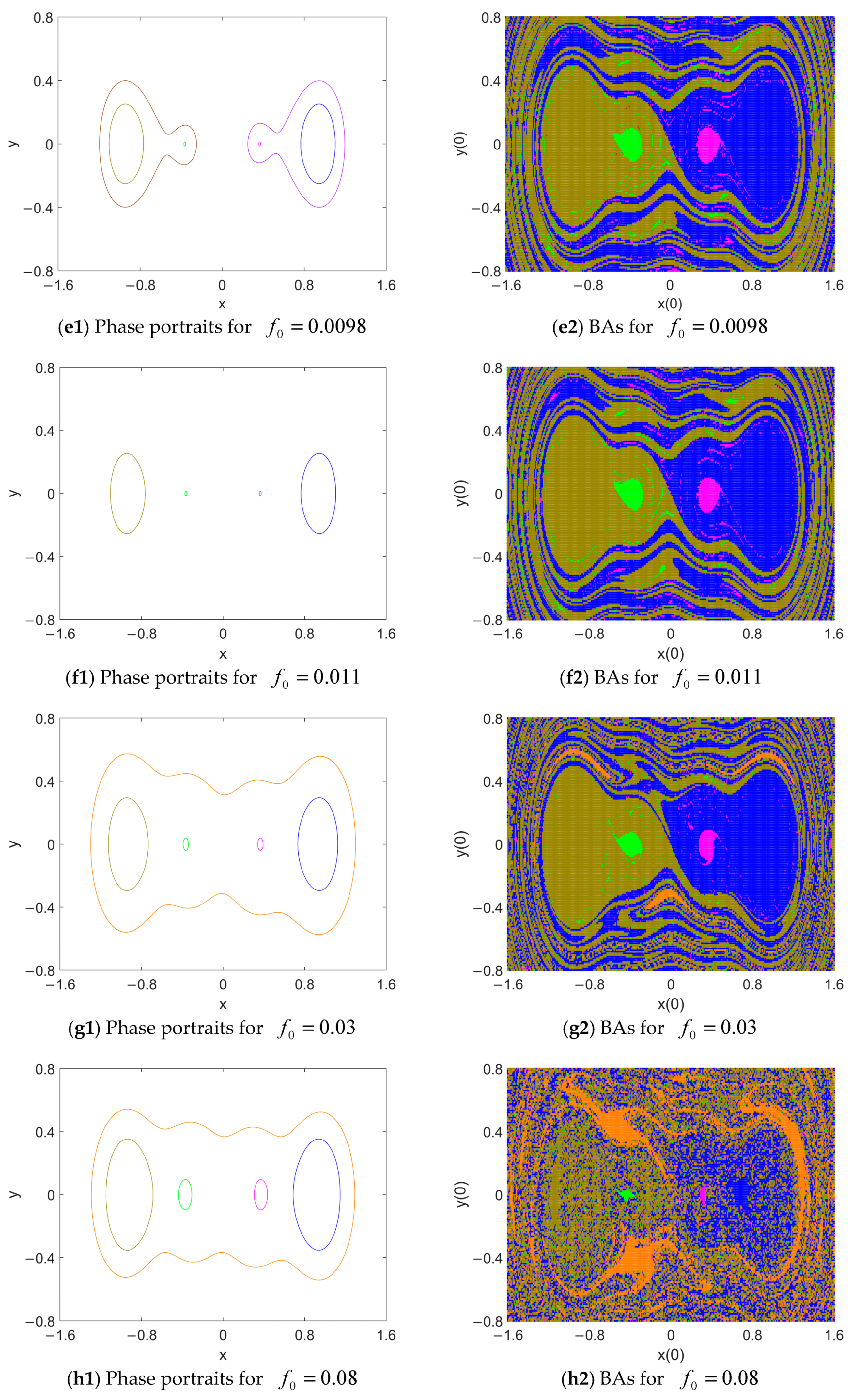
When f 0 exceeds 0.0093, two inter-well responses surrounding the homoclinic orbits emerge (see Figure 11(d1)), coexisting with six intra-well attractors. Since their BAs are discrete points far beyond the vicinity of the well centers (see Figure 11(d2)), they are rare and hidden attractors that can hardly be the final response of system (3).
For f 0 = 0.0098 , the lower-amplitude responses around C 1 , 2 disappear, and the higher-amplitude intra-well responses become locally attractive (see Figure 11(e1,e2)). Still, the inter-well responses are rare and hidden attractors. As f 0 reaches 0.011, the inter-well attractors vanish, and the other attractors and their BAs are nearly unchanged, as illustrated in Figure 11(f1,f2).
When f 0 reaches 0.03, a new inter-well response beyond the quadruple potential wells appears (see Figure 11(g1)). Although its displacement is much larger than others, its BA is so tiny that it can hardly be the final response in practice (see the orange region in Figure 11(g2)).
As f 0 continues to increase, the BA of this inter-well response becomes more and more visible (see Figure 11(h2,i2)). Meanwhile, the BAs of the responses in the vicinity of C 3 , 4 are gradually eroded. Specifically, for f 0 = 0.11 , two attractors vanish, and the BAs of the other attractors are segmented into fractal and discrete pieces, resulting in the high initial condition sensitivity of the system (3). For f 0 = 0.126 , the inter-well response becomes complex when BAs mix with the BAs of the intra-well resonant responses (see Figure 11(j1,j2)).
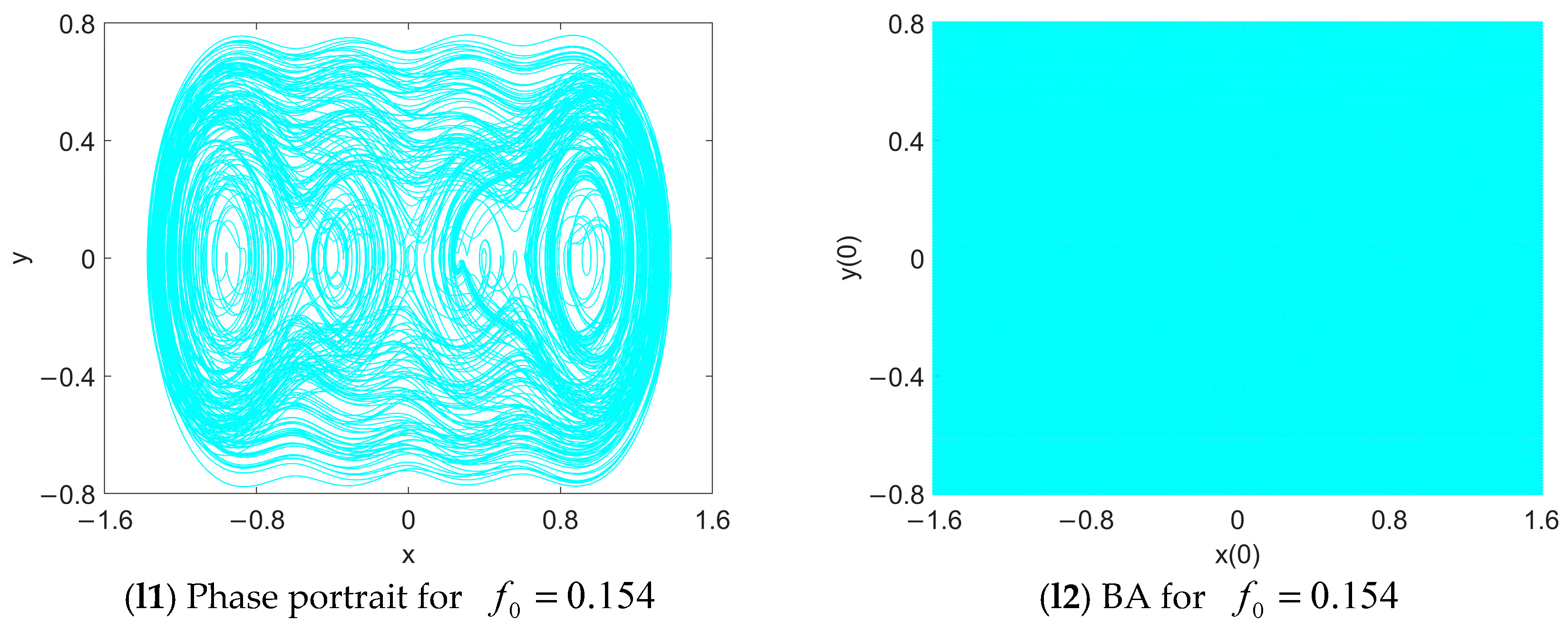
For f 0 = 0.131 , large-displacement chaos emerges, as illustrated in the phase portraits, Poincare maps and frequency spectrums in Figure 11(k1,k3). The BA of this initial condition-sensitive attractor mixes with the BAs of other attractors (see Figure 11(k4)), displaying the double initial-state sensitive characteristics of the chaotic response.
Finally, when f 0 reaches 0.154, only the chaotic response exists, thus making it globally attractive. Since its displacement is large, it is desirable for the engineering applications of this oscillator.

6. Conclusions

In this study, a harmonically excited oscillator comprising one collar and three inclined springs was considered. A comparative analysis of its global dynamics was conducted among single, double and quadruple well configurations. The impact of the structural parameters, the external excitation and the perturbation of the initial states of the oscillatory system on the global dynamics are comprehensively discussed. Firstly, static bifurcations are investigated semi-numerically. Then, the resonant responses in the vicinity of the potential well centers are analyzed via the method of multiple scales, while the inter-well periodic solution is predicted via the averaging method. On this basis, the numerical results in terms of the phase portraits, Poincare maps, frequency spectrums and basins of attraction are presented to verify the accuracy of the qualitative results and to further study the complicated dynamical behaviors of the oscillator. Some novel findings are presented as follows:
(1)
With the decrease in the horizontal distance between the collar and each fixed pin, the system may undergo single, double and quadruple potential wells successively.
(2)
The resonant response in the case of single potential wells displays the stiffness–hardening characteristic, while the intra-well resonant responses in the cases of double and quadruple potential wells display the stiffness–softening characteristic.
(3)
Bistable responses in the vicinity of each well center can be triggered by the variation in the excitation frequency or level due to saddle-node bifurcations of the resonant solutions.
(4)
The double-well configuration is the most practical to achieving a high-amplitude intra-well response under a low-frequency ambient excitation, as the frequency band for the intra-well bi-stability, in this case, is much broader than in the cases of the other two configurations.
(5)
In the case of double potential wells, the increase in the excitation level can induce the inter-well resonant response and complicated dynamical behaviors, including period-3 attractors and chaos, coexisting with the intra-well responses. Their BAs intermingle with each other, showing another type of high initial sensitive phenomenon, unlike the phenomenon of chaos. When the excitation amplitude grows high enough, the inter-well periodic response definitely becomes the final response due to its global attraction.
(6)
In the case of quadruple potential wells, the excitation frequency in the vicinity of the resonant frequency within larger potential wells can help to achieve a higher amplitude final response. With the increase in the excitation level, apart from the periodic responses, various complex responses such as period-2 attractors, period-3 ones and chaos appear as hidden attractors. When the excitation level is high enough, the chaotic response is globally attractive.
The results of this study may provide valuable insights into the design optimization and further applications of geometrically nonlinear oscillators. The manufacturing of such a practical device based upon the oscillatory model, as well as the experiments concerning the initial-state sensitive phenomena such as chaos and jump among multiple responses, will be carried out in our next work.

Author Contributions

Conceptualization, H.S. (Huilin Shang); methodology, H.S. (Huilin Shang); software, H.S. (Huihang Sun); validation, H.S. (Huilin Shang); formal analysis, H.S. (Huilin Shang); investigation, H.S. (Huihang Sun); writing—original draft preparation, H.S. (Hui-hang Sun) and H.S. (Huilin Shang); writing—review and editing, H.S. (Huilin Shang); visualization, H.S. (Huihang Sun); supervision, H.S. (Huilin Shang); project ad-ministration, H.S. (Huilin Shang); funding acquisition, H.S. (Huilin Shang). All authors have read and agreed to the published version of the manuscript.

Funding

This research was funded by the National Natural Science Foundation of China, grant number 11472176.

Data Availability Statement

Data are contained within the article.

Conflicts of Interest

The authors declare no conflicts of interest.

References

  1. Yang, T.; Cao, Q. Novel multi-stable energy harvester by exploring the benefits of geometric nonlinearity. J. Stat. Mech. Theory Exp. 2019, 2019, 033405. [Google Scholar] [CrossRef]
  2. Naseer, R.; Dai, H.; Abdelkefi, A.; Wang, L. Comparative Study of Piezoelectric Vortex-Induced Vibration-Based Energy Harvesters with Multi-Stability Characteristics. Energies 2019, 13, 71. [Google Scholar] [CrossRef]
  3. Liu, C.; Jing, X.; Daley, S.; Li, F. Recent advances in micro-vibration isolation. Mech. Syst. Signal Process. 2015, 56, 55–80. [Google Scholar] [CrossRef]
  4. Zhou, J.; Wang, X.; Xu, D.; Bishop, S. Nonlinear dynamic characteristics of a quasi-zero stiffness vibration isolator with cam–roller–spring mechanisms. J. Sound Vib. 2015, 346, 53–69. [Google Scholar] [CrossRef]
  5. Meng, Q.; Yang, X.; Li, W.; Lu, E.; Sheng, L. Research and Analysis of Quasi-Zero-Stiffness Isolator with Geometric Nonlinear Damping. Shock. Vib. 2017, 2017, 6719054. [Google Scholar] [CrossRef]
  6. Yang, T.; Liu, J.; Cao, Q. Response analysis of the archetypal smooth and discontinuous oscillator for vibration energy harvesting. Phys. A Stat. Mech. Its Appl. 2018, 507, 358–373. [Google Scholar] [CrossRef]
  7. Yang, T.; Cao, Q. Dynamics and high efficiency of a novel multi-stable energy harvesting system. Chaos Solitons Fractals 2020, 131, 109516. [Google Scholar] [CrossRef]
  8. Zhang, J.; Li, X.; Feng, X.; Li, R.; Dai, L.; Yang, K. A novel electromagnetic bistable vibration energy harvester with an elastic boundary: Numerical and experimental study. Mech. Syst. Signal Process. 2021, 160, 107937. [Google Scholar] [CrossRef]
  9. Kenmogne, F.; Wokwenmendam, M.L.; Simo, H.; Adile, A.D.; Noah, P.M.A.; Barka, M.; Nguiya, S. Effects of damping on the dynamics of an electromechanical system consisting of mechanical network of discontinuous coupled system oscillators with irrational nonlinearities: Application to sand sieves. Chaos Solitons Fractals 2022, 156, 111805. [Google Scholar] [CrossRef]
  10. Margielewicz, J.; Gąska, D.; Litak, G.; Wolszczak, P.; Yurchenko, D. Nonlinear dynamics of a new energy harvesting system with quasi-zero stiffness. Appl. Energy 2022, 307, 118159. [Google Scholar] [CrossRef]
  11. Zhang, Q.; Yan, Y.; Han, J.; Hao, S.; Wang, W. Dynamic design of a quad-Stable piezoelectric energy harvester via bifurcation theory. Sensors 2022, 22, 8453. [Google Scholar] [CrossRef]
  12. Von Kluge, P.N.; Sengha, G.G.; Kenfack, W.F.; Talla, L.L.; Kenmoé, G.D.; Kofané, T.C. Fractional dynamical behavior of a new nonlinear smooth and discontinuous (SD) oscillator for vibration energy harvesting with nonlinear magnetic coupling. Eur. Phys. J. Plus 2023, 138, 937. [Google Scholar] [CrossRef]
  13. Yan, Y.; Zhang, Q.; Han, J.; Wang, W.; Wang, T.; Cao, X.; Hao, S. Design and investigation of a quad-stable piezoelectric vibration energy harvester by using geometric nonlinearity of springs. J. Sound Vib. 2023, 547, 117484. [Google Scholar] [CrossRef]
  14. Wang, Z.; Shang, H. Multistability mechanisms for improving the performance of a piezoelectric energy harvester with geometric nonlinearities. Fractal Fract. 2024, 8, 41. [Google Scholar] [CrossRef]
  15. Sun, X.; Jing, X. Multi-direction vibration isolation with quasi-zero stiffness by employing geometrical nonlinearity. Mech. Syst. Signal Process. 2015, 62, 149–163. [Google Scholar] [CrossRef]
  16. Liu, Y.; Xu, L.; Song, C.; Gu, H.; Ji, W. Dynamic characteristics of a quasi-zero stiffness vibration isolator with nonlinear stiffness and damping. Arch. Appl. Mech. 2019, 89, 1743–1759. [Google Scholar] [CrossRef]
  17. Chang, Y.; Zhou, J.; Wang, K.; Xu, D. A quasi-zero-stiffness dynamic vibration absorber. J. Sound Vib. 2021, 494, 115859. [Google Scholar] [CrossRef]
  18. Wang, K.; Zhou, J.; Chang, Y.; Ouyang, H.; Xu, D.; Yang, Y. A nonlinear ultra-low-frequency vibration isolator with dual quasi-zero-stiffness mechanism. Nonlinear Dyn. 2020, 101, 755–773. [Google Scholar] [CrossRef]
  19. Xing, Z.-Y.; Yang, X.-D. A combined vibration isolation system with quasi-zero stiffness and dynamic vibration absorber. Int. J. Mech. Sci. 2023, 256, 108508. [Google Scholar] [CrossRef]
  20. Liu, R.; Shang, H. Global dynamics and bifurcations of an oscillator with symmetric irrational nonlinearities. Fractal Fract. 2023, 7, 888. [Google Scholar] [CrossRef]
  21. Kenmogne, F.; Noah, P.M.A.; Tafo, J.B.G.; Adoum, D.A.; Sali, M.; Abakar, M.T.; Eno, R.; Bell, E.Y. Stability of modulated signals in the damped mechanical network of discontinuous coupled system oscillators with irrational nonlinearities. Arch. Appl. Mech. 2022, 92, 3077–3091. [Google Scholar] [CrossRef]
  22. Chen, H.; Xie, J. Harmonic and subharmonic solutions of the SD oscillator. Nonlinear Dyn. 2016, 84, 2477–2486. [Google Scholar] [CrossRef]
  23. Wang, Z.; Shang, H. Multistability and Jump in the Harmonically Excited SD Oscillator. Fractal Fract. 2023, 7, 314. [Google Scholar] [CrossRef]
  24. Han, N.; Cao, Q. A parametrically excited pendulum with irrational nonlinearity. Int. J. Non-Linear Mech. 2017, 88, 122–134. [Google Scholar] [CrossRef]
  25. Yang, T.; Cao, Q. Delay-controlled primary and stochastic resonances of the SD oscillator with stiffness nonlinearities. Mech. Syst. Signal Process. 2018, 103, 216–235. [Google Scholar] [CrossRef]
  26. Li, Z.; Cao, Q.; Nie, Z. Stick-slip vibrations of a self-excited SD oscillator with Coulomb friction. Nonlinear Dyn. 2020, 102, 1419–1435. [Google Scholar] [CrossRef]
  27. Han, Y.; Cao, Q.; Ji, J. Nonlinear dynamics of a smooth and discontinuous oscillator with multiple stability. Int. J. Bifurc. Chaos 2015, 25, 1530038. [Google Scholar] [CrossRef]
  28. Hao, Z.; Cao, Q.; Wiercigroch, M. Nonlinear dynamics of the quasi-zero-stiffness SD oscillator based upon the local and global bifurcation analyses. Nonlinear Dyn. 2016, 87, 987–1014. [Google Scholar] [CrossRef]
  29. Wang, J.; Huang, W.; Huang, L. Global dynamics and bifurcation for a discontinuous oscillator with irrational nonlinearity. Commun. Nonlinear Sci. Numer. Simul. 2023, 119, 107073. [Google Scholar] [CrossRef]
  30. Dudkowski, D.; Prasad, A.; Kapitaniak, T. Perpetual points and hidden attractors in dynamical systems. Phys. Lett. A 2015, 379, 2591–2596. [Google Scholar] [CrossRef]
  31. Brezetskyi, S.; Dudkowski, D.; Kapitaniak, T. Rare and hidden attractors in Van der Pol-Duffing oscillators. Eur. Phys. J. Spec. Top. 2015, 224, 1459–1467. [Google Scholar] [CrossRef]
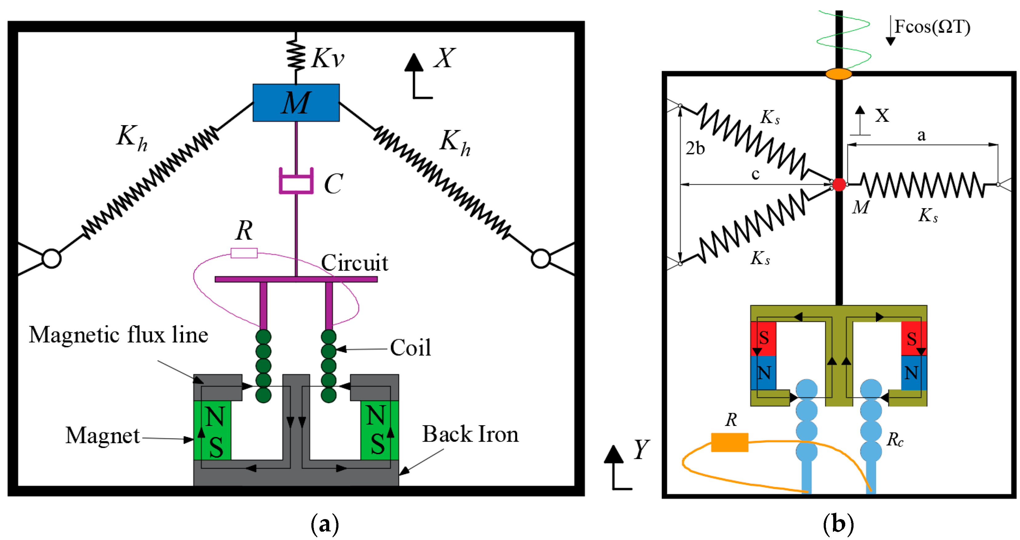
Figure 1. Obliquely set-up springs in electromagnetic VEHs: (a) VEH with a pair of springs (SD oscillator); (b) VEH with three springs.
Fractalfract 08 00202 g001
Figure 2. Schematic diagram of the oscillatory system.
Fractalfract 08 00202 g002
Figure 4. Variation in the resonant solutions in the vicinity of O(0, 0) with the excitation for α = 0.8 : (a) amplitude–frequency response; (b) the amplitude of the periodic solution vs. the excitation level.
Fractalfract 08 00202 g004
Figure 5. Variation in the attractors and their BAs with the rise in ω for α = 0.8 and f 0 = 0.01 .
Fractalfract 08 00202 g005aFractalfract 08 00202 g005b
Figure 6. Variation in the resonant solutions in the vicinity of C ± ( ± x c , 0 ) with the excitation of α = 0.4 : (a) amplitude–frequency response; (b) response amplitude vs. the excitation level.
Fractalfract 08 00202 g006
Figure 7. Amplitude variation in the inter-well periodic response with the increase in f 0 .
Fractalfract 08 00202 g007
Figure 8. Variation in the coexisting responses and their BAs with the rise in f 0 at ω = 0.45 .
Fractalfract 08 00202 g008aFractalfract 08 00202 g008bFractalfract 08 00202 g008c
Figure 9. Unperturbed orbits for α = 0.2 and β = 0.6 .
Fractalfract 08 00202 g009
Figure 10. Amplitude variation in the intra-well resonant solutions with the dimensionless excitation for α = 0.2 : (a) amplitude–frequency response around C 1 , 2 ; (b) the amplitude of the response around C 1 , 2 vs. the excitation level; (c) amplitude–frequency response around C 3 , 4 ; (d) the amplitude of the response around C 3 , 4 vs. the excitation level.
Fractalfract 08 00202 g010
Figure 11. Evolution of attractors and basins of attraction with the rise in f 0 for ω = 1.47 .
Fractalfract 08 00202 g011aFractalfract 08 00202 g011bFractalfract 08 00202 g011cFractalfract 08 00202 g011d
Table 1. Equilibria of the unperturbed system (4) for β = 0.6 and different values of α.
Value of αNumber of EquilibriaPositions of Equilibria
0.81O(0,0)
0.43C±(±0.351,0), O(0,0)
0.27C1,2(±0.945,0), S1,2(±0.530,0), C3,4(±0.365,0), O(0,0)
Disclaimer/Publisher’s Note: The statements, opinions and data contained in all publications are solely those of the individual author(s) and contributor(s) and not of MDPI and/or the editor(s). MDPI and/or the editor(s) disclaim responsibility for any injury to people or property resulting from any ideas, methods, instructions or products referred to in the content.