1. Introduction
The Fast Steering Mirror (FSM) plays a crucial role in the adjustment and stabilization of the visual axis or beam pointing in optical systems [
1,
2]. It offers several advantages, including its compact size, precise construction, wide bandwidth, and rapid speed. Consequently, it has found extensive applications in significant domains such as space laser communication, astronomical telescopes, optical stability, high-precision laser processing equipment, and carrier laser systems [
3,
4,
5].
Using the Lissajous scan trajectory is a promising way to remove issues resulting from the raster scan trajectory in several advanced applications [
6,
7]. Although the repetitive control schemes, which are tailed to track periodic trajectories, have been successfully utilized to improve the tracking performance of the Lissajous trajectories, the enabled performance is limited due to the unavoidable dynamic characteristics. Especially, the trajectory formed by the combination of high-frequency sine waves in grating scanning contains several high-frequency components, which often lead to larger tracking errors.
The researchers have made great efforts to solve the above-encountered drawbacks. Currently, the sinusoids-based non-raster scanning patterns, including the spiral scan, Lissajous scan, cycloid scan, rotational scan, and so on, have been investigated, and thus contribute to a significant increase in the scanning speed. Among these patterns, the Lissajous scan trajectories [
8,
9], a self-repeating pattern where both the X and Y-axis are driven by sinusoids with a suitable frequency ratio, can be regarded as a promising alternative to the raster scan trajectories with their extremely simple spectrum for both axes and easy implementation for sequential scanning. Although this scanning pattern can alleviate the existing problem of the traditional trajectory itself, the advanced control techniques are still a requisite to handle the residual tracking errors resulting from the hysteresis nonlinearity for ensuring tracking precision.
With the development of optoelectronic detection technology, the requirements for detection range and accuracy, along with the design of scanning FSMs, are becoming increasingly strict. To meet the need for large field-of-view scanning and detection, the travel requirements of scanning FSMs are also becoming more stringent, which increases the difficulty of assembling and debugging components. In addition, as a scanning FSM follows the phases of acceleration (start), uniform swing, deceleration (stop), and acceleration (return) during operation, it needs to move according to a predetermined curve. Optical scanning trajectories are widely used in FSM applications. Lissajous scan trajectories, which follow a self-repeating pattern in which both the X-axis and the Y-axis are driven by sinusoids with a suitable frequency ratio, can be regarded as a promising alternative to raster scan trajectories, with their extremely simple spectrum for both axes and easy implementation for sequential scanning [
6,
7]. Although repetitive control schemes have been successfully utilized to improve the tracking performance of Lissajous trajectories, most existing application research has focused on piezoelectric-driven scanners, which are limited by the small travel characteristics of piezoelectric ceramics themselves, resulting in limited scanning travel.
The main driving mechanisms for FSMs are voice coil motors and piezoelectric ceramics [
10,
11,
12]. The voice coil motor is a direct drive motor with the advantages of a large stroke, small size, and low drive voltage [
13]. Piezoelectric ceramic actuators have the advantages of small size, light weight, high accuracy and resolution, high frequency response, large bearing capacity, and no noise [
14,
15]. Compared with piezoelectric ceramics, voice coil motors have a lower driving voltage and larger stroke. Therefore, voice coil motor drivers are better suited to applications with large strokes.
Position control is the basic working mode of FSMs and requires not only precise positioning but also a high response speed and minimal overshoot in the position transition process [
16]. FSM control is a typical position control strategy, as only the position sensor is used as the feedback component [
17]. Existing FSM control systems are based on feedback control, namely a post-correction step: when an output error is detected, the controller adjusts the output. Therefore, when the tracking error is large, the use of large gains to adjust the control output may lead to overshoot [
18,
19]. A controller based on the traditional proportional–integral–derivative (PID) method typically produces a large control output under the joint action of the gain and the integration link [
20]. Differential control and velocity measurement feedback are employed in classical control strategies to increase system damping and reduce overshoot, but they afford only limited reductions in overshoot [
21]. Consequently, many researchers have developed novel control strategies, such as plug-in module acceleration feedback control [
22], model reference adaptive control [
23], and feedforward control, based on the results of error and disturbance observations [
24,
25,
26].
Control strategies for FSMs have been reported in the literature. G. Wang et al. [
27] proposed a comprehensive model of a two-axis FSM system through synthetical consideration of each physical component. V. Hassani et al. [
28] represented various mathematical models of hysteresis and different methods of system identification. J. Ling et al. [
29] proposed a new online neural network based sliding mode control scheme to obtain robust adaptive precision motions. The nonlinearity of piezoelectric actuator has been identified online and compensated for using singularity-free neural networks. A. K. Babarinde et al. [
30] proposed the design, analysis, and experimental validation of the simultaneous method for a positive acceleration, velocity, and position feedback control-based combined damping and tracking scheme. C. Chang [
31] proposed a four-degree-of-freedom (DOF) actuator for FSM compensation systems to compensate for 4-DOF laser errors. Nastaran Nikooienejad et al. [
32] presented a control scheme for video-rate atomic force microscopy with a rosette pattern. They designed an iterative learning controller to improve the tracking performance of the feedback-controlled scanner by rejecting the repetitive disturbances arising from system nonlinearities. C. Li et al. [
33] proposed a modified repetitive control approach for high-speed tracking of nano-positioning stages. Based on the above research, an effective control strategy requires accurate modeling of the system, early data collection, and the addition of sensors. The methods reported in the studies above rely heavily on early data or prior information, and they may even increase system costs. Therefore, practical engineering applications using these methods are not feasible or achievable. Active disturbance rejection controllers are widely used in engineering practice due to their simple structure, strong anti-interference ability, convenience of adjustment, and lack of model dependence. Active disturbance rejection controllers, which do not rely on the model information of the controlled object, provide a unique solution for the control of Lissajous scanning objects [
34]. However, many problems with this approach, such as complex parameter tuning, high control bandwidth, short sampling intervals, and large observation errors, remain to be solved [
35]. The FOPD controller is an extension of the traditional PD controller [
36,
37]. By adding an adjustable fractional order, the FOPD design can be more flexible, and attain better performance [
38]. The FOPD controller can perform better than classical PD. Nevertheless, for high-control performance requirements, the capacity of the FOPD is still limited.
Aiming to overcome the above limitations on the use of FSMs for Lissajous scanning tracking, we designed a fractional-order active disturbance rejection controller (FOADRC) for precisely tracking Lissajous scan trajectories with voice coil motors driven FSM. A forward tracking differentiator (TD) was applied to process the position command and a second TD was introduced into the feedback channel to obtain the differential of the output value. By fully exploiting known information, such as the model and sensor output, we designed a reduced-order ESO with fractional order proportional differentiation (FOPD) controller to enhance the dynamic performance of the position step response. To evaluate the performance of the FOADRC in tracking Lissajous scan trajectories, comparative experiments with a PID controller and ADRC were conducted. The experimental results verified the advantages of the proposed FOADRC for FSMs in Lissajous scanning.
For Lissajous scanning applications, a detailed model was produced and a controller was designed for voice coil motors driven FSM. The main contributions of this study are: (a) By tracking the transition process of the differentiator to obtain the set value and obtaining its non-integer order differential signal, the system can quickly and smoothly achieve zero overshoot, meeting the requirements of Lissajous scanning without overshoot. (b) Based on the model characteristics of the controlled object and combined with external sensor information, the extended state observer was redesigned. The improved reduced order extended state observer was found to achieve accurate observation of the extended state. (c) We combined the FOPD controller and replaced the PD controller, by adding an adjustable fractional order, the FOPD design can be more flexible, and attain better performance in terms of improved steady-state error, good disturbance rejection, and superior behavior with nonlinearities.
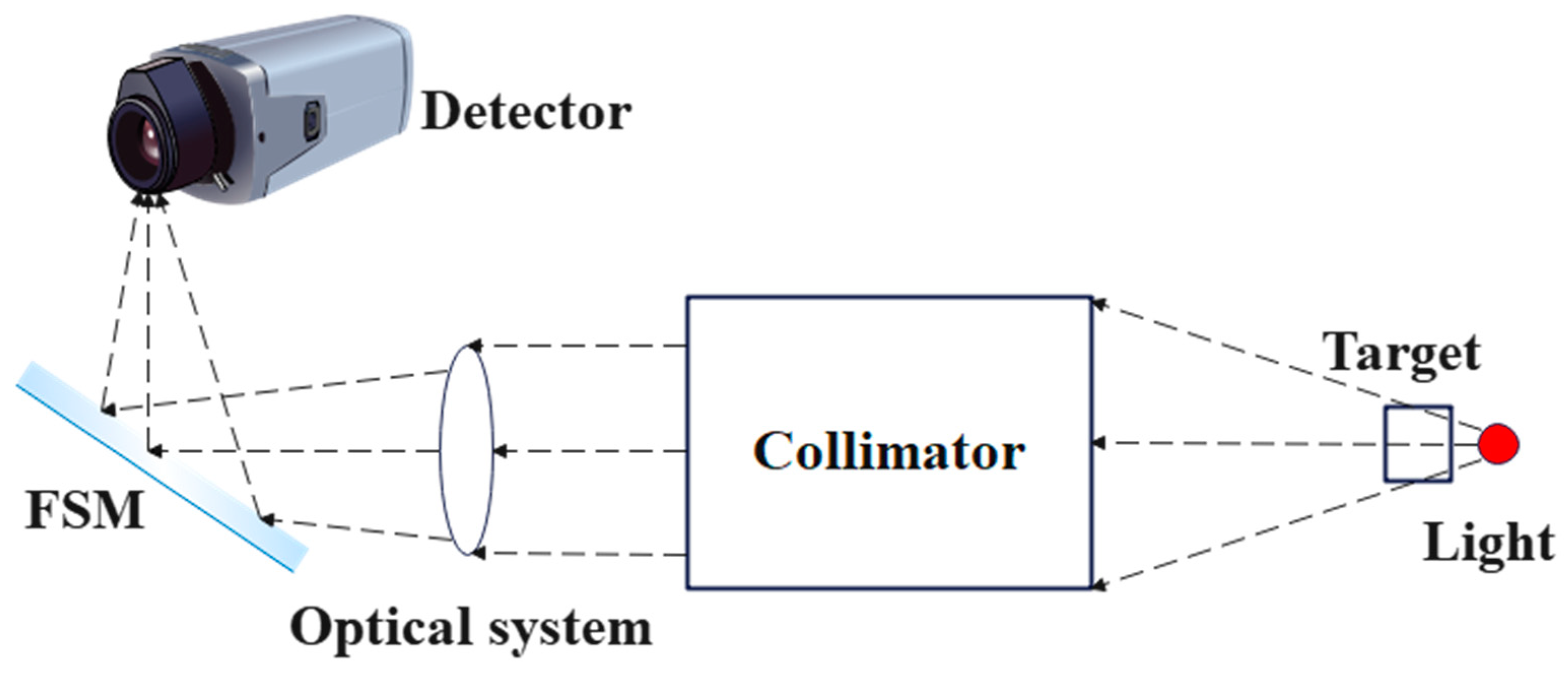
3. Dynamic Model and Parameter Design of Control System
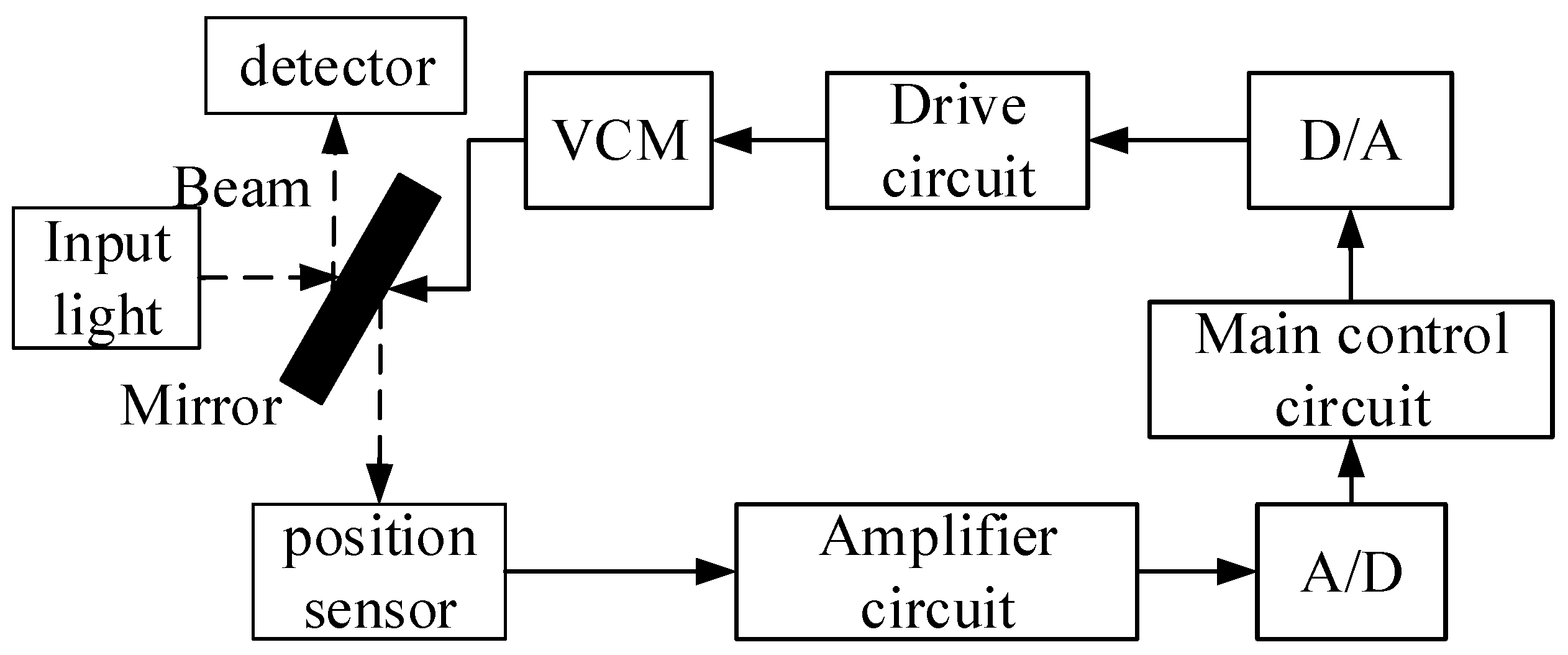
The design of FSM system is a typical nonlinear control problem. FSM is susceptible to external interference factors such as base disturbances. Therefore, in order to achieve better control effects and higher performance indicators, it is necessary to propose corresponding control methods for applications. The voice coil motors drive FSM mainly consists of the following parts: the control circuit, the drive circuit, a mirror, and the position sensor [
39,
40].
Figure 2 shows Block diagram of the position control loop of the FSM.
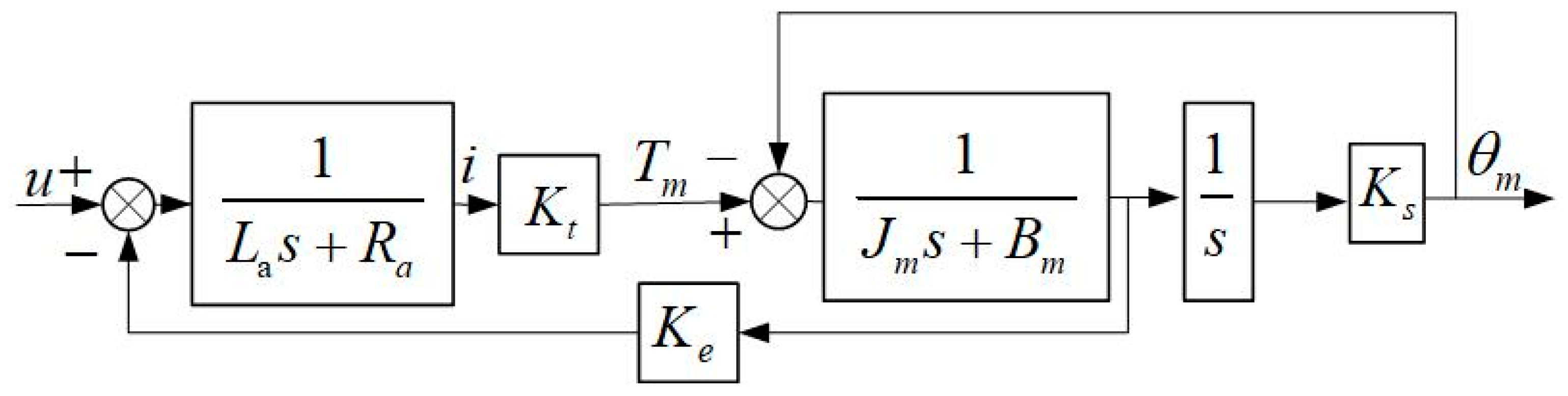
According to the dynamic characteristics, the block diagram of FSM is established as shown in
Figure 3.
In
Figure 3,
La is armature inductance,
Ra is armature resistance,
i is armature current,
Kt is electromagnetic torque constant,
Ke is back EMF coefficient,
Tm is motor output torque,
Jm is motor inertia,
Bm is viscous damping coefficient of the motor end,
θm is motor angle,
Ks is mechanical stiffness of the shaft.
According to
Figure 3, the transfer function of the controlled object is obtained by
In actual systems, the inductance of the motor is very small and can be ignored, so the above equation can be simplified as
The second-order oscillation system is used to fit the model of the FSM.
represents the gain,
is the natural frequency and
is the damping coefficient.
We obtain the model of the FSM through the frequency scanning method and then perform a discrete Fourier transform on the input and output signals to calculate the amplitude and phase of the input and output signals at each frequency point. Finally, at each frequency point, the output amplitude is compared to the input amplitude, and the output phase is subtracted from the input phase to obtain the corresponding amplitude response and phase response. By using the Matlab System Identification Toolbox in Matlab and combining it with the derived theoretical model, the FSM model can be fitted based on the sweep frequency data. Thus, the values of natural frequency and resonance coefficient can be obtained.
Although some advanced control algorithms for FSM systems can achieve good closed-loop control effects through theoretical analysis and proof, some algorithms have complex structures, high computational complexity, and unclear physical meanings of parameters, which hinders their application in practical engineering. This paper focuses on the research of FSM control for imaging scanning, emphasizing not only the in-depth study of control theory and methods, but also the rationality of theoretical research oriented towards applications.
An extended state observer (ESO) employs a new state variable to reflect all of the disturbances affecting a control output. In most engineering applications, the output values of the front and back sampling periods are differentiated. Because sampling periods are small, large differential noise may easily be introduced during this process. Therefore, in this paper, a TD was incorporated into the feedback channel to obtain the differential of the output value as the input of the ESO. The ESO was used to realize the observation and estimation of the system states and external disturbances, and incorporated into the closed-loop control. The traditional nonlinear ESO is difficult to implement in engineering, due to its large number of tuning parameters and complex calculations. Therefore, in this study, a linear ESO (LESO) was used to enhance the observational accuracy of the system state and the ADRC performance [
41,
42,
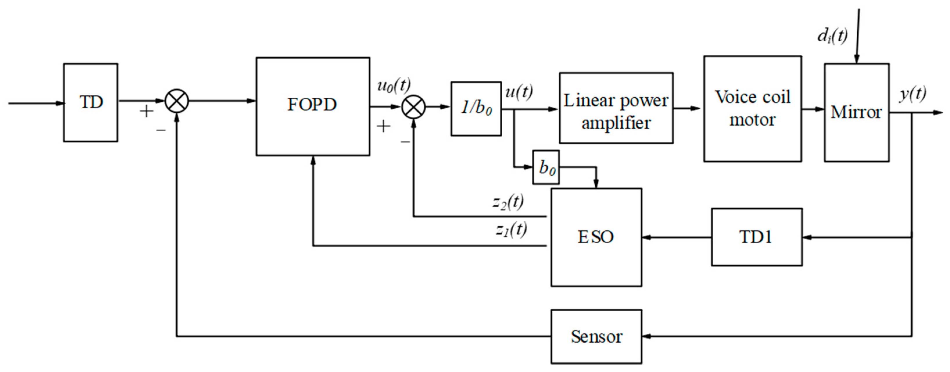
43]. A FOADRC was designed by adding a TD to the forward channel and an ESO to the feedback channel, with the FOPD control rate designed according to the system characteristics.
Figure 4 depicts the structural block diagram.
Figure 4 shows that the TD was used to track the input and could thus arrange the transition process. TD1 was used to track the output and extract the differential signal of the output.
The state-space matrix form is
where
,
,
,
,
is the total disturbance.
The state observer after being expanded from the second order to the third order is
where
is the observer gain vector.
As the position sensor signal is known,
is the estimate of position sensor
,
is the estimate of the differential of the output signal
, and
is the estimate of the total disturbance
.
The position of the FSM could be directly measured by the sensor. The full-order ESO is transformed into a reduced-order ESO. The reduced-order state observer model becomes
where
is the differential of the position sensor output, and
is the total disturbance.
where
,
,
,
,
.
According to the bandwidth design method, the observer bandwidth was set to
, and the expected characteristic formula is obtained
Then, the observer gain vector is obtained
As the actual control model could be transformed into a unit second-order underdamped system
The FSM model was simplified as a second-order integral series, and the control design was completed by using the design theory of bandwidth parameters and fractional order proportional differentiation (FOPD) controller. Compared with traditional integer order proportional differential controllers, Fractional Order Proportional Derivative Controller (FOPD) increases the adjustable differential order,
where
,
, and
represents differential adjustment factors.
is the Laplace operator,
is the adjustable differential order factor and the value range between 0 and 1.
is the natural frequency and
is the cut-off frequency.
4. Simulation Analysis
Model identification is used to identify the theoretical model. The actual model is obtained by the sweep frequency method.
The specific parameter values of Equation (18) are obtained through the frequency sweep method and system model identification method. The parameters such as open-loop gain, damping, and natural frequency are known in the FSM model. Based on the above FOADRC and ADRC controller design results, determine the parameters that the controller needs to be tuned. Confirm the specific values of each PID parameter based on the design bandwidth. After calculating the above parameters, FSM is used as the experimental object, and TMS320F28335 DSP is used as the processor. The above parameters are written into the DSP through Code Composer Studio to convert the analog signals into discrete signals, thereby obtaining the discretized difference equation. During each sampling cycle, sensor data collection and control algorithm calculations need to be completed.
The sampling frequency selected for the system was 40 kHz. The operation step and filter factor were designed as
. The controller bandwidth, observer bandwidth, differential adjustment factor, and disturbance compensation factor of the controller needed to be set according to the aforementioned controller design results. The fast factor of the TD for processing position-related instructions was set to 4,000,000; and the fast factor of TD1, which was used to extract output differential signals in FOADRC, was set to 10,000,000. The parameters of the FOPD controller are set as: the proportional factor is 2.5, the differential factor is 0.05, and the adjustable differential order factor is 0.7. The signal with an amplitude of 1000 µrad and a cycle of 500 Hz was mixed with a random signal, and the resulting mixed noise signal was used as the position input command.
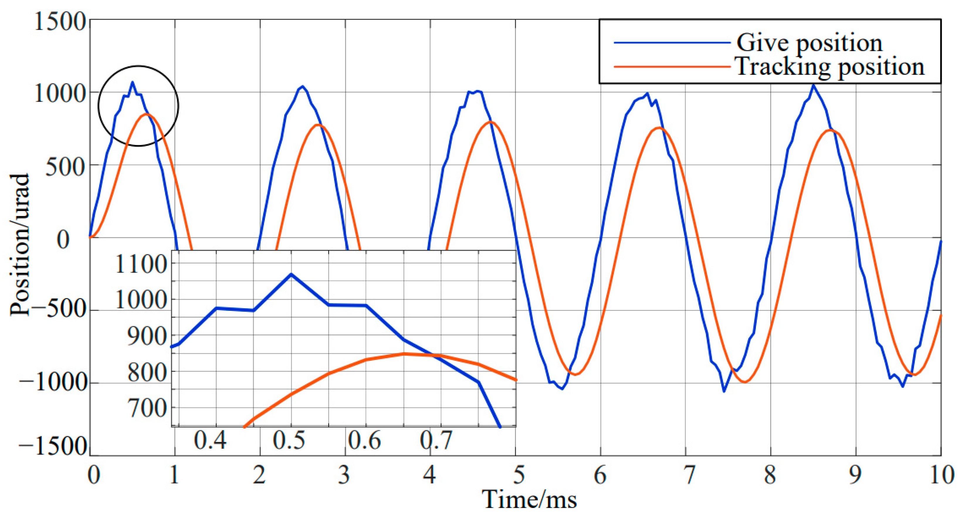
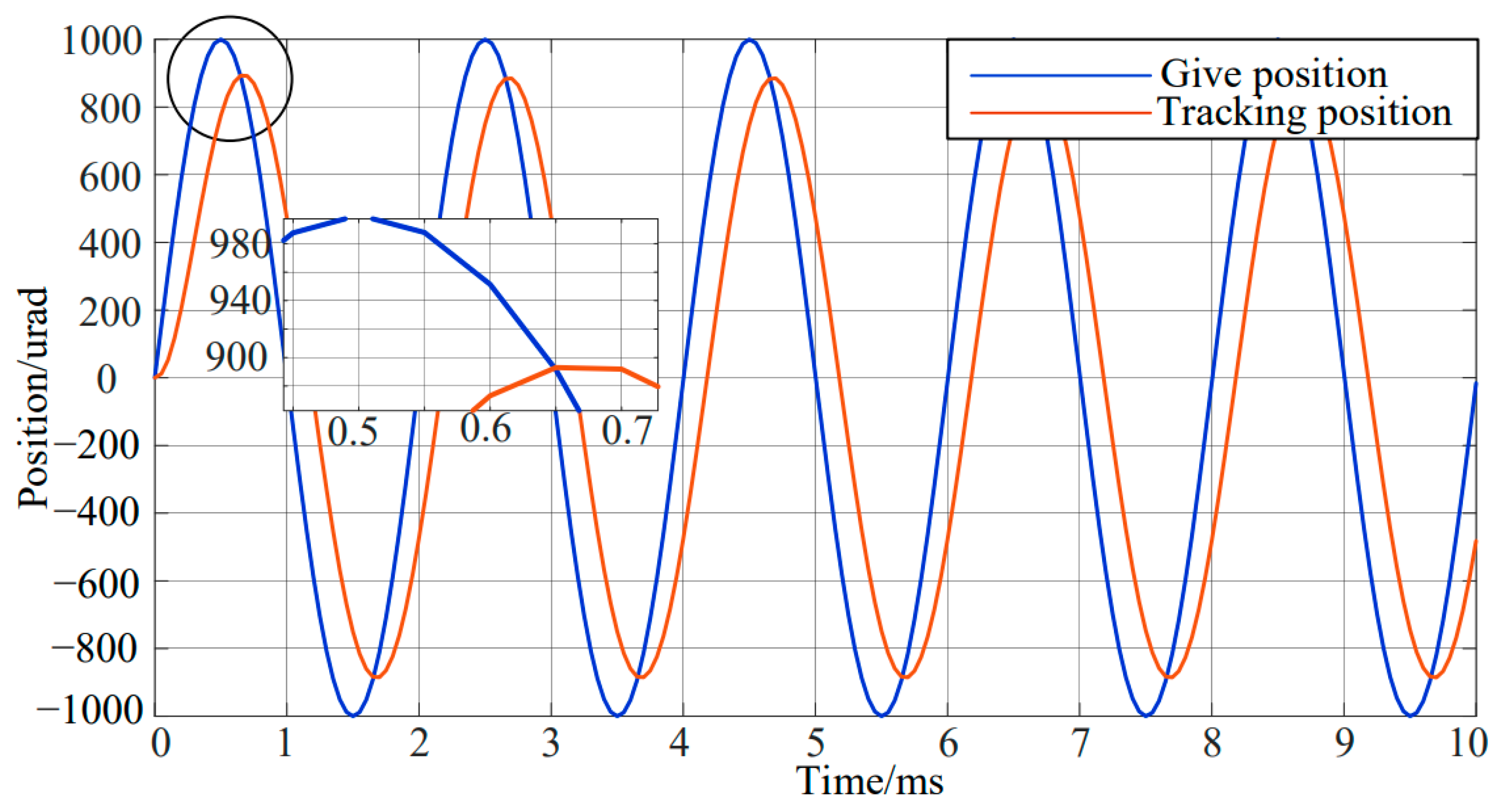
Figure 5 presents the tracking position response curve of the FOADRC algorithm without random signal, and
Figure 6 illustrates the tracking position response curve of the FOADRC algorithm with random signal.
When simulating, there is a certain delay in the actual given and transmission, and there is also a certain lag in the system response, so there is actually a phase between the give position signal and the tracking position. As presented in
Figure 5, devised an algorithm could tracking of high-frequency sine signal, which may have a phase lag of −27°. As shown in
Figure 6, the system effectively tracks the input signal and has a good suppression effect on random noise. The response signal almost coincided with the command signal, and the phase lag was −27°. The lag could be reduced by adjusting the size of the fast factor. An increase in the value of the fast factor resulted in a decrease in the phase lag. The selection of the fast factor depends on the bearing capacity and available control capacity of the controlled object. Specifically, the greater the bearing capacity and available control capacity of an object, the higher the value of the fast factor, resulting in a closer match to the reference step input form. However, the bearing and control capacities of an actual system are limited. Thus, the fast factor can only be increased by a certain extent.
5. Experimental Verification
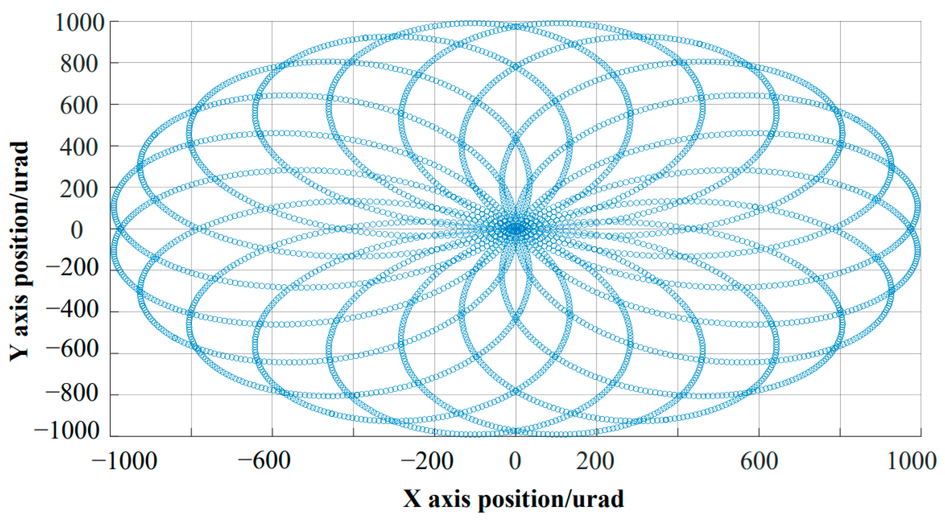
To meet the practical requirements of a large field of scanning detection, through the study of FSM design and scanning methods, the transformation from Orthogonal coordinate system to Cartesian coordinate system is designed to achieve large stroke and high bandwidth scanning curves. After designing a scanning scheme to synthesize the scanning curve from the X and Y orthogonal coordinate system to the Cartesian coordinate system, the petal scanning curve was achieved.
Figure 7 shows the scan curve after synthesizing the X and Y orthogonal coordinate systems into the Cartesian coordinate system. The scanning frequency of the X-axis in
Figure 7 is 500 Hz, and the scanning frequency of the Y-axis is 350 Hz. With the increase in scanning frequency, the frequency requirements for FSM are becoming higher and higher.
As shown in
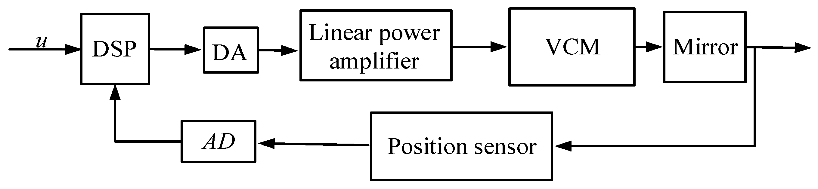
Figure 7, the high-frequency undistorted repetitive scanning curve can provide a good prerequisite for scanning imaging. To verify the tracking characteristics and control algorithm, two axis FSM designed in this paper was tested using TMS320F28335 DSP as the processor. The control schematic diagram is shown in
Figure 8. The DSP collects sensor data through an A/D converter and outputs the control signal of the voice coil motors to the linear driving circuit through the D/A converter. The control voltage of the voice coil motors is equal and opposite in direction to achieve a differential push and pull effect. To improve FSM performance, a higher sampling frequency should be used as much as possible. This system adopts a sampling frequency of 200 kHz and a sampling period of 0.000005 s. During each sampling cycle, it is necessary to complete sensor data collection and control algorithm calculations.
As the scanning frequency increased, the frequency requirements became increasingly high. The actual dual axis input was converted to a Cartesian coordinate system with different scanning frequencies, and the synthesized motion trajectory is shown in
Figure 8. As shown in
Figure 8, through a reasonable closed-loop control strategy, it was possible to achieve trajectory planning for large stroke and high frequency scanning.
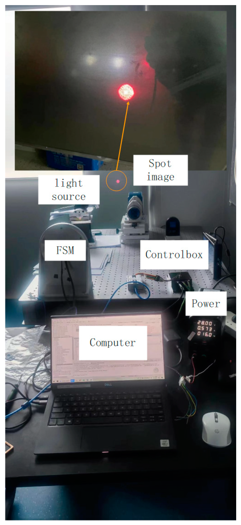
The scanning experimental platform is shown in
Figure 9. FSM is fixed on the air flotation platform, and the light source is placed parallel to the zero position of the FSM. When the FSM scans at high frequency according to the input command, the actual scanned petal image is projected onto the wall. By observing the effect of the petals and collecting feedback data from the two axes of the system, the closed-loop scanning effects of PID, ADRC, and the proposed control strategy are compared, as shown in
Figure 10,
Figure 11 and
Figure 12.
Figure 9 shows the scanning pattern obtained by using FSM to scan
Figure 7. Scanning experiments were conducted on the above scanning curves in the laboratory. Due to the insufficient exposure time of the camera, it was not possible to fully capture the dynamics of the curves. Therefore, during recording, some dynamic curves may be recorded incompletely. However, we can still analyze and compare the scanning curves from the recorded curves, and analyze the advantages and disadvantages of the scanning curves corresponding to the three different methods proposed in this experiment based on the requirements of the experiment.
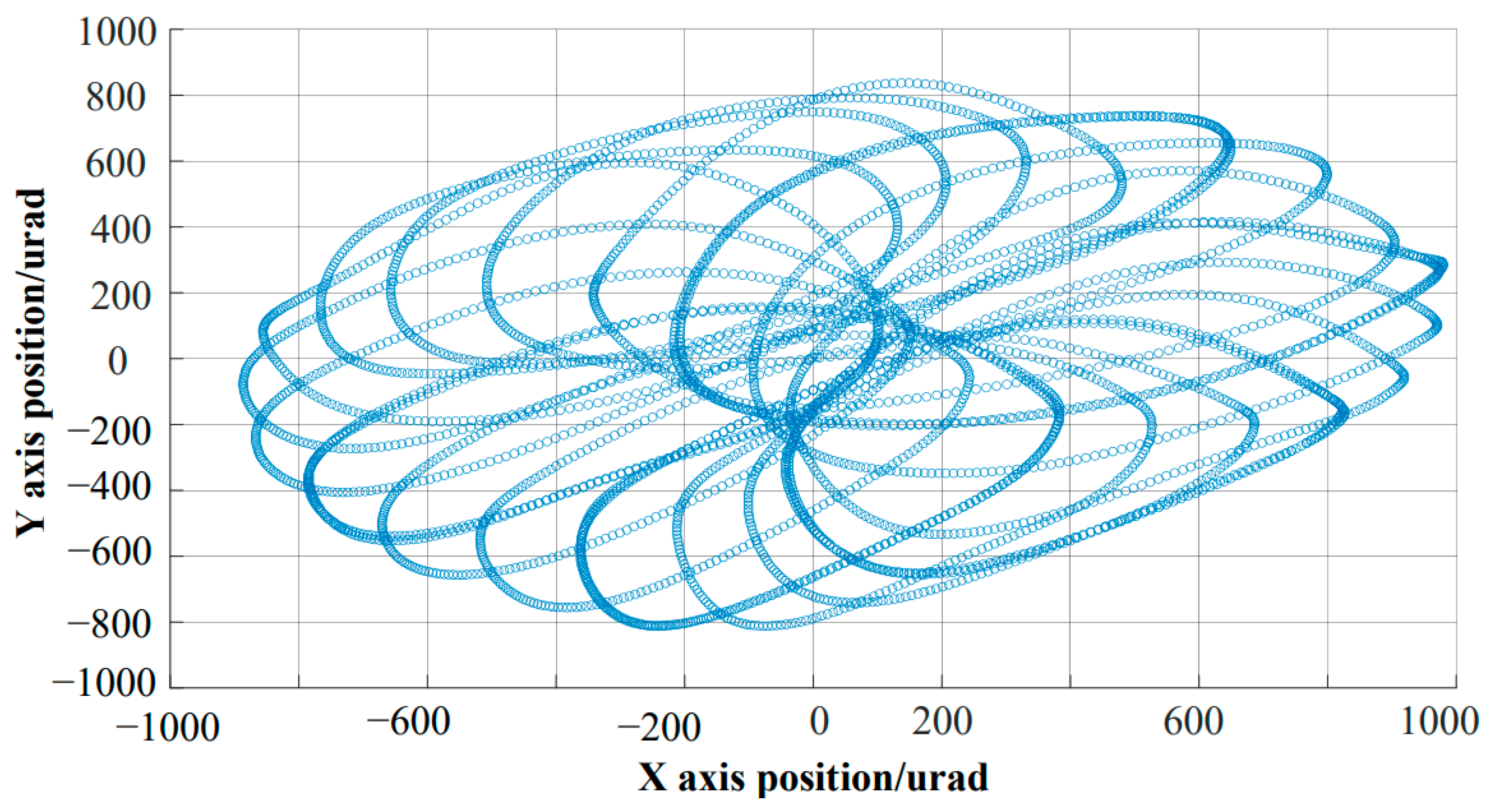
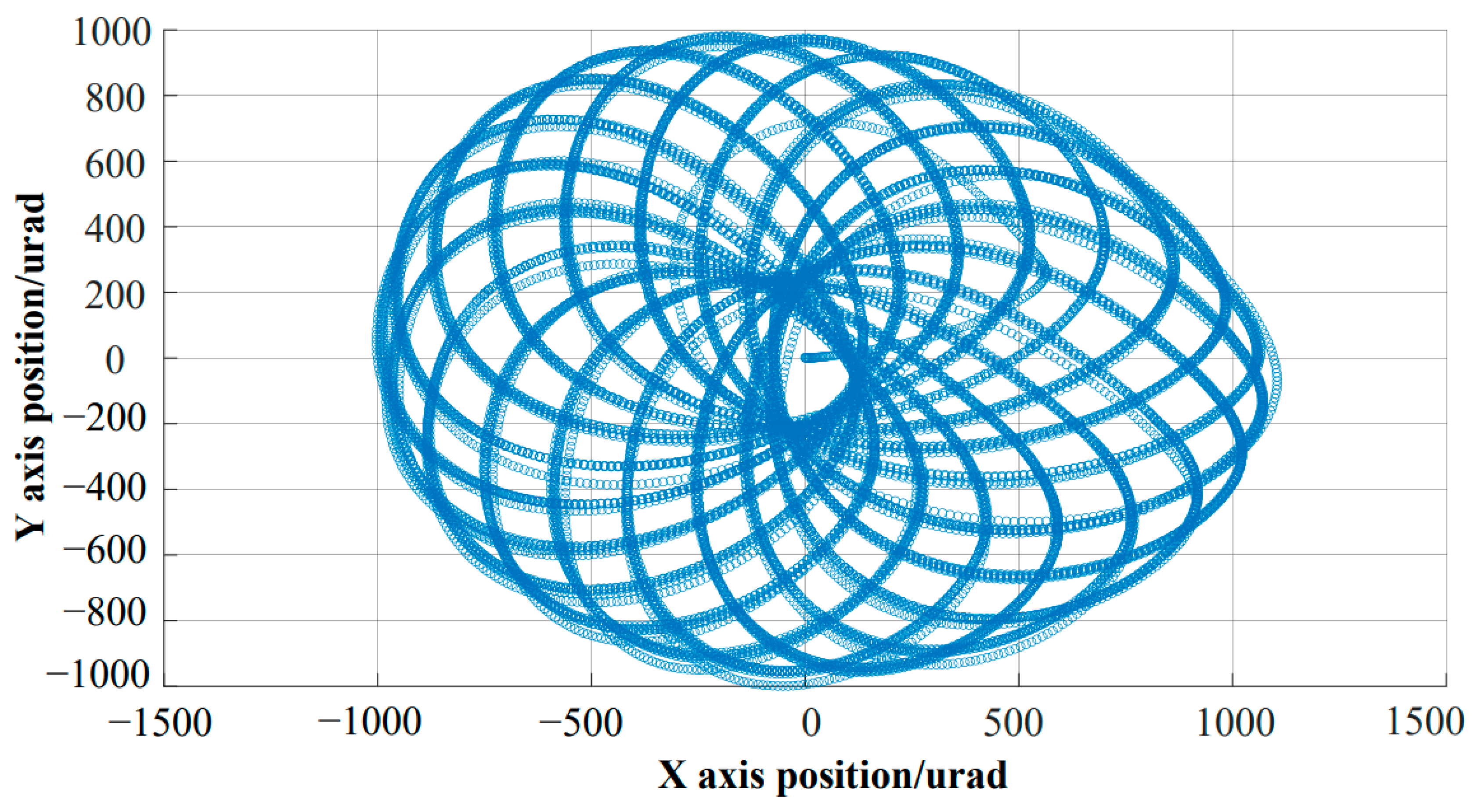
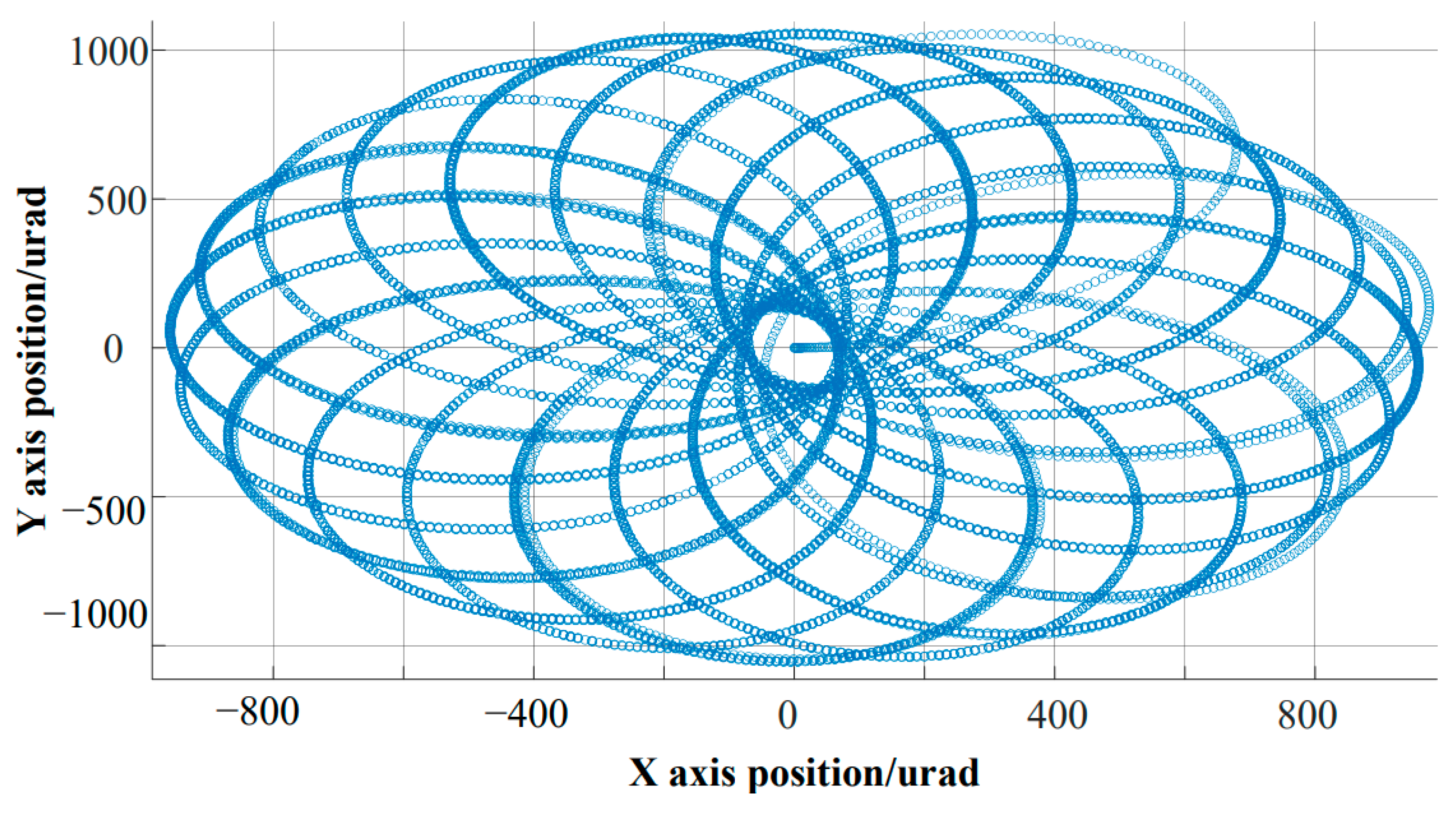
By adopting three control strategies, the Lissajous curve tracking function of the same system was achieved. Comparing the three actual tracking effects, it is evident that the traditional PID closed-loop control strategy led to distortion in high-frequency scanning, causing the scanning function to fail. The ADRC strategy had the problem of local distortion, making it impossible to ensure repeatability. In contrast, the FOADRC strategy ensured a repetitive tracking curve. Although there were some point distortions, the input scanning curve was reproduced, so changing the distortion did not cause the scanning function to fail. These results verify the advantages of the FOADRC in repetitive Lissajous scanning tracking.
From the actual tracking curves of the three methods mentioned above, it can be seen that using the PID controller is constrained by the contradiction between overshoot and bandwidth, and therefore cannot achieve excellent tracking results. The ADRC strategy can track most of the input curves, but due to the complexity of parameter adjustment and the limitation of controller bandwidth, it cannot achieve excellent tracking results. The above parameter adjustment process is too complex, and when the scanning frequency changes, it may be necessary to readjust the parameters. The use of the FOADRC strategy takes into account the advantages of both ADRC and PID control strategies, and the adjusted parameters are not as many as those of traditional ADRC. Therefore, parameter tuning is simple. When the external frequency changes, the parameters can fine tune to achieve tuning.


