Article

A New Optimized FOPIDA-FOIDN Controller for the Frequency Regulation of Hybrid Multi-Area Interconnected Microgrids

1
Department of Electrical, Faculty of Technology and Education, Sohag University, Sohag 82524, Egypt
2
Department of Electrical Engineering, Faculty of Engineering, Sohag University, Sohag 82524, Egypt
3
Department of Electrical Engineering, Faculty of Energy Engineering, Aswan University, Aswan 81528, Egypt
4
Faculty of Engineering, King Salman International University, South Sinai, El-Tor 46511, Egypt
5
HuManis Research Center (EA 7308), EM Strasbourg Business, Strasbourg University, 67081 Strasbourg, France
6
Department of Mathematics, College of Sciences, King Saud University, Riyadh 11451, Saudi Arabia
*
Author to whom correspondence should be addressed.
Fractal Fract. 2023, 7(9), 666; https://doi.org/10.3390/fractalfract7090666
Submission received: 4 July 2023 / Revised: 2 August 2023 / Accepted: 3 August 2023 / Published: 4 September 2023

Abstract

:
This paper proposes a combined feedback and feed-forward control system to support the frequency regulation of multi-area interconnected hybrid microgrids considering renewable energy sources (RESs). The proposed control system is based on a fractional-order proportional-integral-derivative-accelerated (FOPIDA) controller in the feed-forward direction and a fractional-order integral-derivative with a low-pass filter compensator (FOIDN) controller in the feedback direction, referred to as a FOPIDA-FOIDN controller. Moreover, the parameters of the proposed FOPIDA-FOIDN controller (i.e., twelve parameters in each area) are optimally tuned using a proposed hybrid of two metaheuristic optimization algorithms, i.e., hybrid artificial gorilla troops optimizer (AGTO) and equilibrium optimizer (EO), and this hybrid is referred to as HGTOEO. The robustness and reliability of the proposed control system are validated by evaluating its performance in comparison to that of other counterparts’ controllers utilized in the literature, such as PID, FOPID, and tilt integral derivative (TID) controller, under the different operating conditions of the studied system. Furthermore, the proficiency of the proposed HGTOEO algorithm is checked against other powerful optimizers, such as the genetic algorithm, Jaya algorithm, improved Jaya algorithm, multi-verse optimizer, and cost-effective multi-verse optimizer, to optimally design the PID controller for the load frequency control of the studied two-area interconnected microgrid. The MATLAB simulation results demonstrate the viability and dependability of the proposed FOPIDA-FOIDN controller based on the HGTOEO algorithm under a variety of load perturbations and random production of RESs.

1. Introduction

Due to the increased use of fossil fuels in recent decades, which have boosted carbon dioxide levels, the climate change phenomenon has become more evident. Additionally, electric power generated from conventional power plants has high production costs. All this has led to the breakthrough of renewable energy sources (RESs) as a clean alternative, which represents an effective strategy to address environmental and pollution issues. With the increasing use of RESs, such as wind and solar sources in electric power systems, severe system perturbations have occurred caused by variations in wind speed and solar radiation [1,2]. Additionally, the intermittent nature of RESs creates numerous control issues, such as significant changes in frequency or voltage, which increase the likelihood of a network failure, resulting in the quality of the power also declining [3,4].
The crucial issue of frequency management in power networks with high RESs has received considerable research interest. One of the most crucial operations, when a power system is running, is load frequency control (LFC) [5]. Several control techniques have been proposed by earlier researchers to address the LFC problem. The goal of these investigations is to keep the frequency at the nominal value. Interconnected power systems have a vast number of variables to be controlled as well as massive, intricate pieces, which is another issue. As a result, system operation and control procedures are more complicated. Due to the multi-region rise, it is particularly challenging to stabilize the frequency in each region. As a result, LFC requires the development of more intelligent controllers. Mathematical models were developed for the LFC of microgrids considering RESs, such as in [4,6]. To keep frequency changes within acceptable limits, battery energy storage systems (BESSs) and flywheel battery energy storage systems (FBESSs) were integrated into microgrids with a high penetration of RESs [7,8].
The microgrid’s controllers control the power exchange and keep frequency within acceptable bounds. Both the reactive and active demands fluctuate continuously because of the dynamic load variation, creating oscillations. The automatic generation control (AGC) allows for the speedy recovery of the oscillations to the normal level. The imbalance between the load and power generation causes the frequency involved in the power system to fluctuate. A network of tie-lines linking various areas of increased sway could result from this. The control of the tie-line power and generator output is required to maintain the stability of the system dynamics. The three major objectives of AGC are to reduce frequency oscillations, lower tie-line power within acceptable limits, and ensure that the generation system operates well. There have been numerous studies on the LFC of the system running in different operational modes under the multi-area power system paradigm [9].
A fractional-order (FO) controller was employed with the output of the fuzzy self-tuning controller for the LFC of a power system [10]. The effectiveness of the control system in reducing frequency deviation and accelerating response time was improved using FO control systems. The whale optimization algorithm (WOA) has also been applied to find the scale coefficients in the fuzzy controller and the orders in the proposed FO controller. According to [11], a dual-input interval type-2 fuzzy FOPI-FOPD (DIT2-FOPI-FOPD) cascade controller has several uncertainties (PV, Wind, and Load), and the control parameters are dynamic. Using the cutting-edge improved salp swarm algorithm (I-SSA) method, the controller’s gains were fine-tuned [11]. The scaling factors, rule base weights, and the FOPID controller parameters in [6] were optimized using the teaching–learning-based optimization (TLBO) technique. In [3], a combination between LFC and automatic voltage regulator (AVR) was proposed for the voltage/frequency stability of a multi-area hybrid power system considering generation rate constraints (GRCs) and communication time delay (CTD). To obtain the proper parametric gains for the proposed controller in [3], a differential evolution-artificial electric field algorithm (DEAEFA) was applied. A coordinated control technique between the secondary frequency control and superconducting magnetic energy storage (SMES) unit was adopted to enhance the frequency stability of the Egyptian power system (EPS) with high-level wind power penetration [12,13,14]. The particle swarm optimization (PSO) algorithm was used to optimally design the PI controller to reduce system frequency deviations [13]. Moreover, the PID controller based on moth swarm optimization was coordinated with SMES to support the frequency stability of a real multi-source power system [9]. To maintain the dynamic security of an islanded microgrid considering high RES penetration, the coordination between LFC and digital over/under frequency relay (OUFR) was undertaken [15].
On the other hand, due to the limitations of conventional controllers, model predictive control (MPC) was used to reduce the system frequency deviations that result from the high penetration of RESs [16]. In [17], the quasi-oppositional harmony search algorithm (QOHSA)-based tuned MPC was proposed, and its performance on the LFC of the single- and two-area hybrid power system (HPS) models assisted by conventional units, plug-in hybrid electric vehicles (PHEVs), diesel engine generators (DEGs), and tidal turbine generators (TTGs) was analyzed. The testing of the superiority of the QOHSA-tuned MPC over the traditional QOHSA-tuned PID was conducted after comparing the performance of the QOHSA over those of other algorithms in MPC tuning. A two-area interconnected microgrid system with an automated LFC made possible by demand–response support (DRS) was the subject of the research in [18]. Numerous traditional controllers were optimized with the yellow saddle goatfish algorithm (YSGA) and were utilized for the LFC of a two-area interconnected microgrid [19]. A FOPID controller was developed in [20] to suppress the frequency deviation in a power system. The parameters of the FOPID controller were established by minimizing the integral time absolute error (ITAE) of the frequency deviation using the PSO technique. To improve the effectiveness and dependability of a ship’s power system, the shipboard microgrid system was proposed in [21] as an intelligent microgrid whose LFC was conducted using intelligent control technology. A PID controller was designed in [1] along with the integration of a BESS and a plug-in hybrid electric vehicle (PHEV) for frequency regulation in a hybrid solar power system. Artificial neural networks (ANNs) were utilized to accurately estimate solar PV production when sun irradiance and cell temperature were inputs to the model [4]. The authors of [22] introduced a two-degrees-of-freedom 2DOF-PID controller to regulate frequency and power variations in a two-area power system. The dragonfly algorithm (DA) is one of the most effective design tools for the suggested strategy. The authors of [23] applied the cascaded PI-(1+PD) controller architecture for the LFC of a microgrid. The proposed controller’s customizable parameters were derived using the dragonfly search algorithm (DSA), and the suggested controller design was denoted as PI-(FO P+PD). A FO model predictive control (FOMPC) strategy was recommended for the optimal frequency control of an island microgrid [24]. The proposed method was best designed using the dragonfly algorithm (DA). To regulate the frequency/power of the two-area interconnected power system, a unique integral-based-weighted goal fitness function (IB-WGFF) as constructed as the objective function to be reduced, modifying the PI-(1+PD)-cascaded controller design to increase efficiency. To obtain a quick convergence in PI-(1+PD), factor one (1) was changed in the suggested design. In PI-(1+PD), factor one (1) was transformed into a fractional operator dependent on the input signal, which helps to speed up the controller’s performance while keeping it simple. The suggested controller design was represented as PI-(FO P+PD), and the adjustable parameters of the proposed controller were taken from the dragonfly search algorithm (DSA). For the best frequency control of an island microgrid, a fractional-order model predictive control (FOMPC) approach was suggested.
In [25], the authors presented a new optimal structured interval type-2 fractional order fuzzy proportional derivative/fuzzy proportional-integral controller for the secondary LFC of a networked shipboard multi-microgrid. They employed the concepts of the black-hole optimization algorithm and Levy flight to propose an enhanced Jaya algorithm to adjust the setting of the established structured controller. An adaptive type-2 fuzzy PID controller for LFC in an AC microgrid system was reviewed by [26]. The designed controller is a nonlinear controller that can handle the system’s nonlinearities and uncertainties in a better way. In [27], an optimal fuzzy PI controller design was presented to solve load frequency control in microgrids. Class topper optimization was introduced to obtain the optimal gain of the fuzzy PI. In [28], the authors proposed a control strategy for the LFC of smart power grids with high wind-farm penetrations. The strategy involves using a fuzzy logic controller with three inputs from wind velocity, frequency deviations, and wind velocity changes per second, along with an improved pitch angle controller and a smart learning-based intelligent controller (BELBIC) to facilitate frequency stability and lower variations in the output power of conventional units.
In [29], the authors proposed a tuning method based on a neural network algorithm (NNA) to optimize the parameters of the FOPID controller for the automatic voltage regulator (AVR) system for set point tracking, noise suppression capability, load rejection capability, controller effort, and model uncertainty in various components of the AVR system. In [30], the authors proposed an ANFIS-based LFC approach for multi-interconnected power systems comprising renewable energy sources. The approach was designed using the antlion optimizer (ALO) to determine the optimal gains of the PI controller. The input and output of the optimized PI controller were used to train the adaptive neuro-fuzzy inference system (ANFIS)-LFC with Gaussian surface membership functions. In [31], the simulation results show that the proposed scheme improves the dynamic response and performance of the LFC system and ensures stability despite load variation and parametric uncertainties. In [32], the authors proposed a controller design for frequency control in microgrid communities using neural networks. The proposed control is a PID controller, while the design is based on neural networks. In [33], an optimal LFC algorithm was proposed for the frequency regulation of microgrids in the presence of network-induced delays. The algorithm uses a quadratic cost function to minimize frequency deviations and is solved iteratively using backward recursion.
The main contribution of this paper can be summarized as follows.
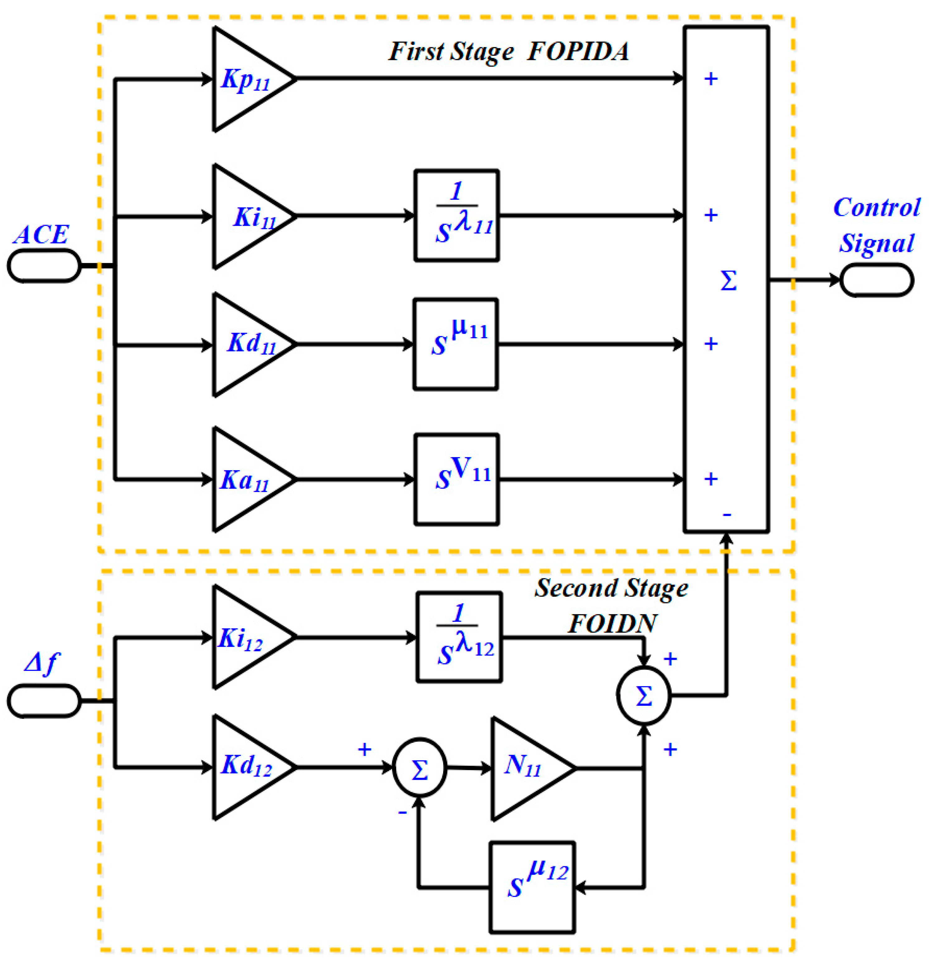
  • Proposing the well-structured combination of the fractional-order proportion-integral-derivative-accelerated (FOPIDA) controller in the feed-forward direction and a fractional-order integral-derivative with a low-pass filter compensator (FOIDN) controller in the feedback direction, which is referred to as the FOPIDA-FOIDN controller, as a supplementary (secondary) controller for the secondary LFC in the islanded multi-microgrid.
  • Applying a hybrid optimization algorithm, named HGTOEO algorithm, which is a combination of an artificial gorilla forces optimizer (AGTO) and an equilibrium optimizer (EO) to adjust the proposed LFC controller gain of the microgrid.
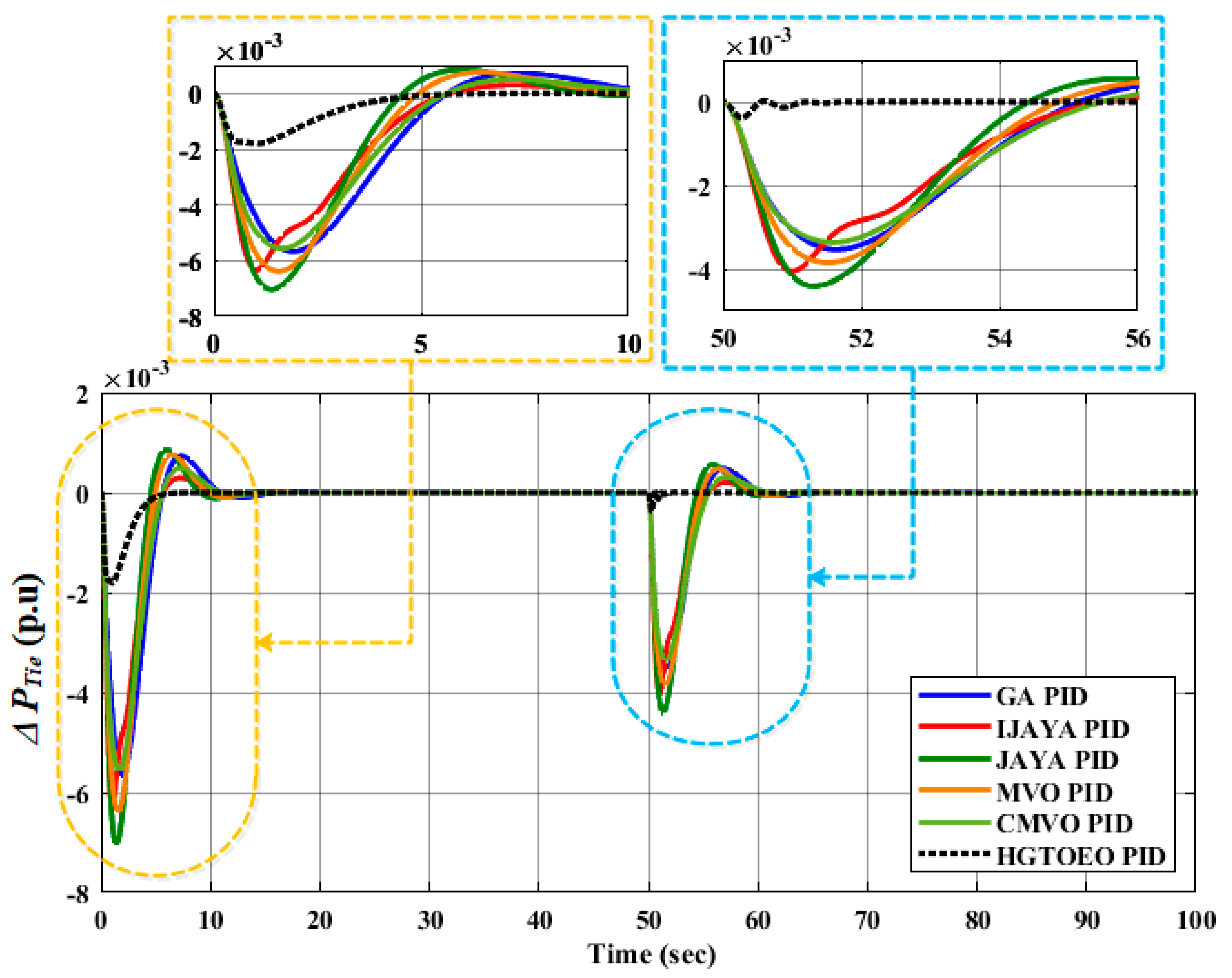
  • Validating the superiority of the proposed HGTOEO by comparative analysis with genetic algorithm (GA), JAYA algorithm, improved JAYA (IJAYA) algorithm, multi-verse optimizer (MVO), and chaotic multi-verse optimizer (CMVO) in a similar structure to the PID controller.
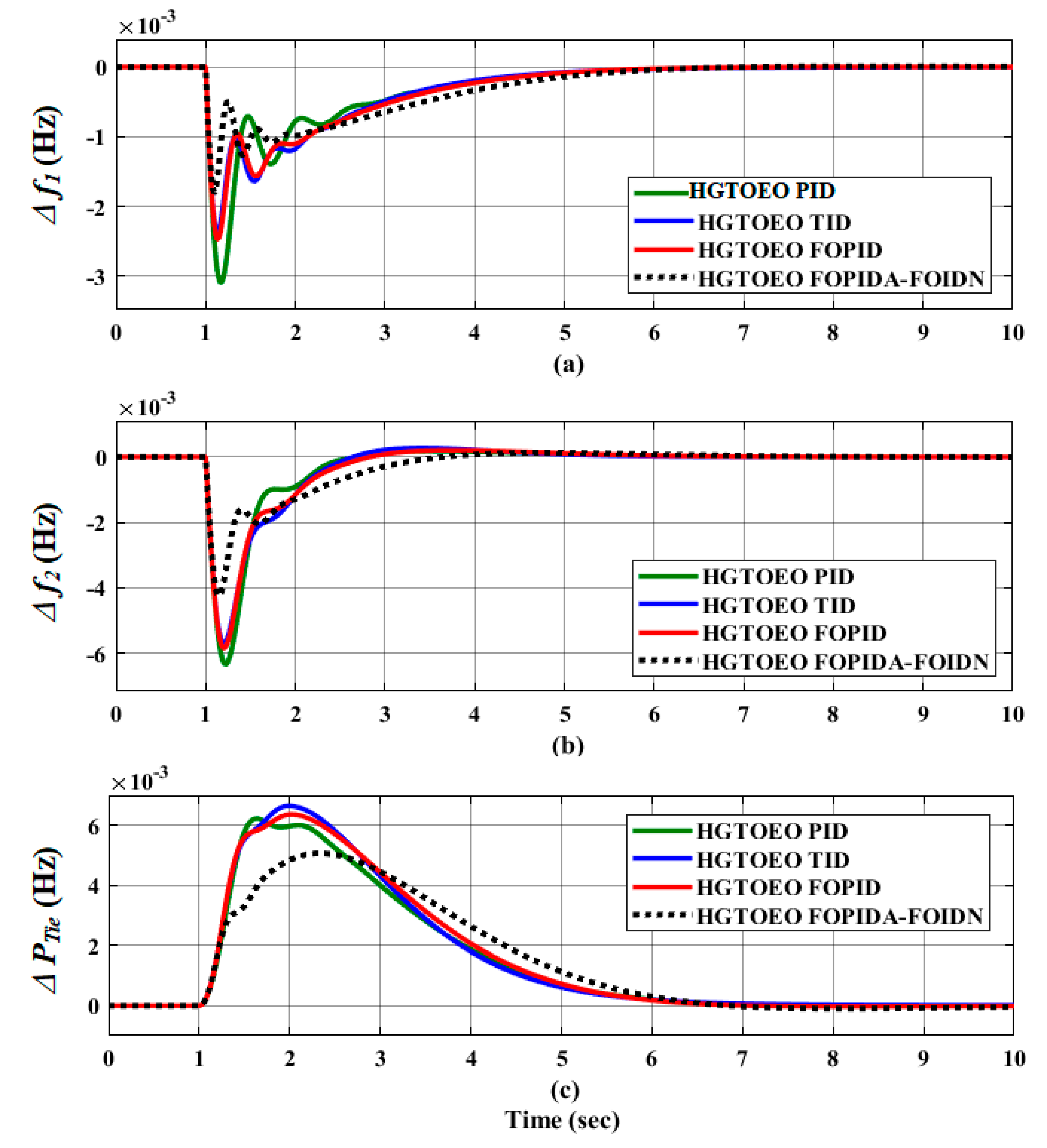
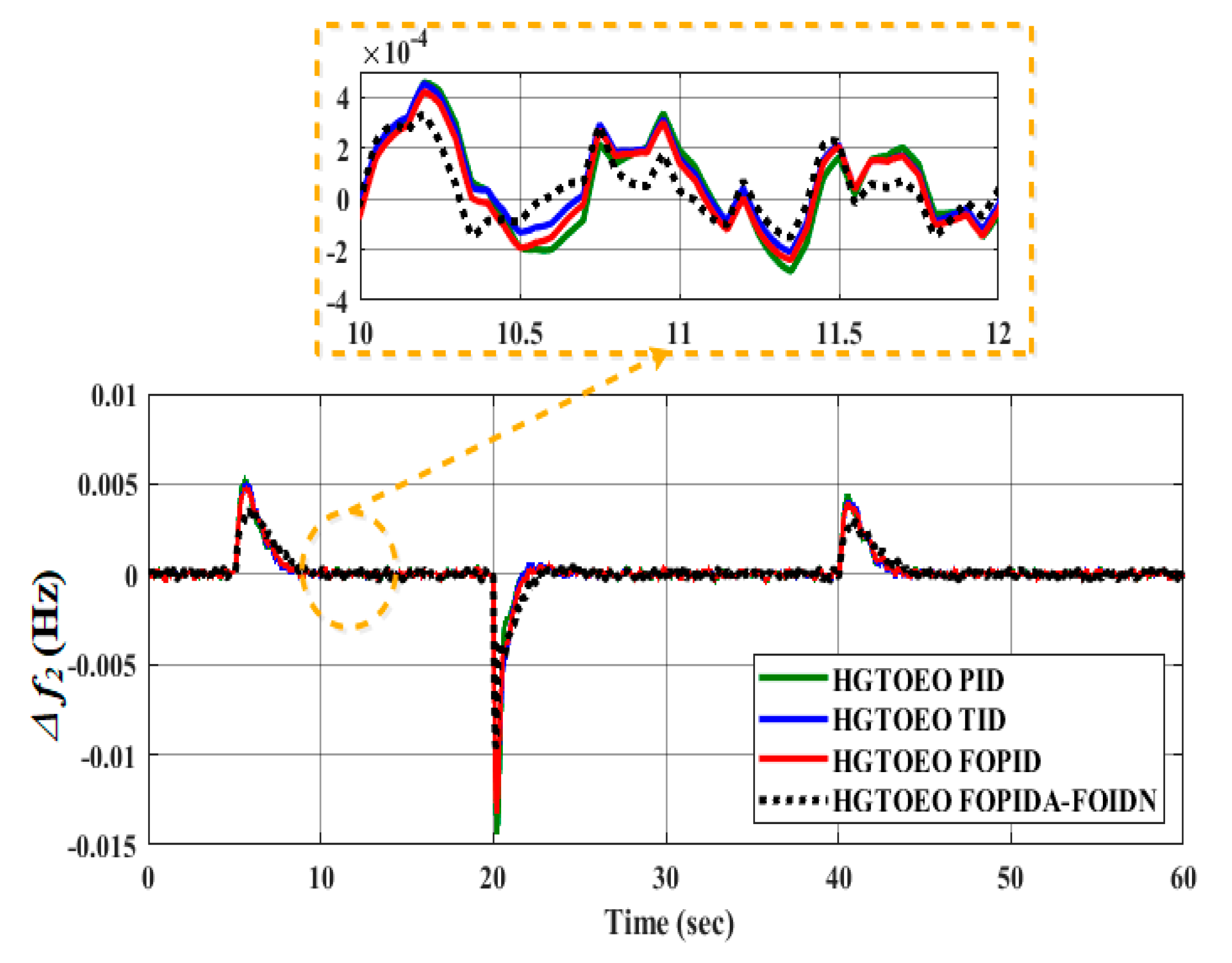
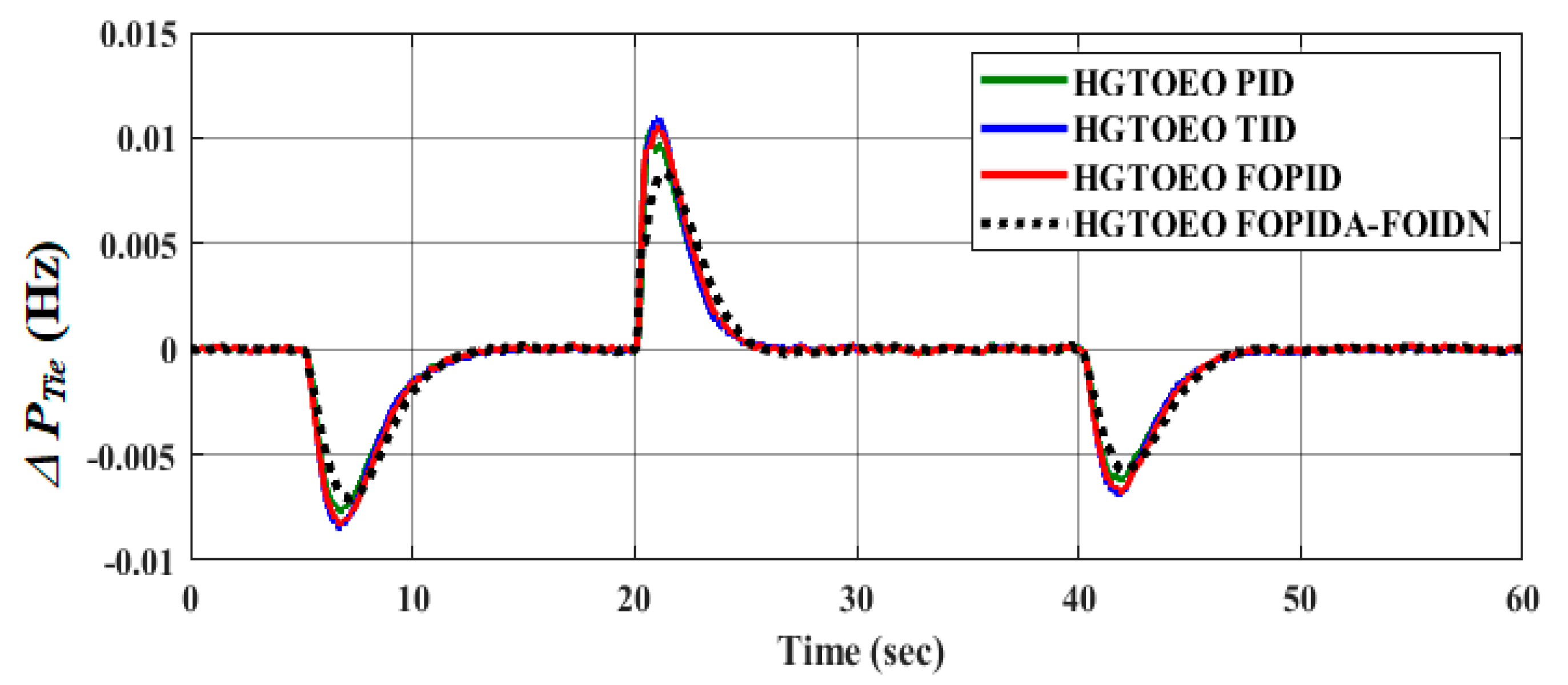
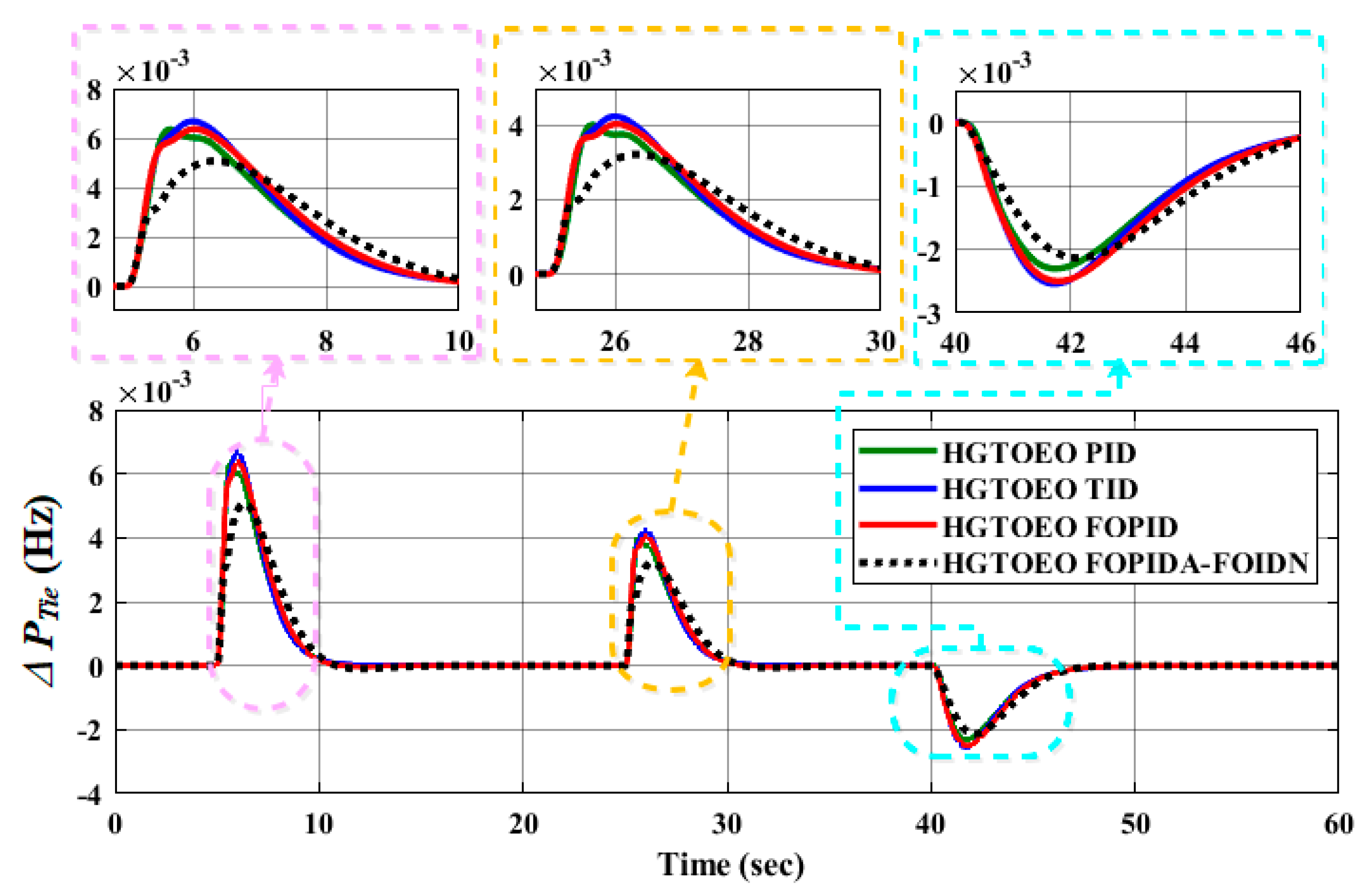
  • Validating the superiority of the proposed FOPIDA-FOIDN controller by comparing it to other controllers used in the literature (such as FOPID, TID, and PID controllers) under load/RES fluctuations.
The following is the breakdown of this paper. Section 2 presents the two-area interconnected power system. Section 3 presents the description and configuration of the proposed controller. Section 4 provides the proposed hybrid optimization algorithm. The results and discussion are presented in Section 5, while the conclusion is presented in Section 6.

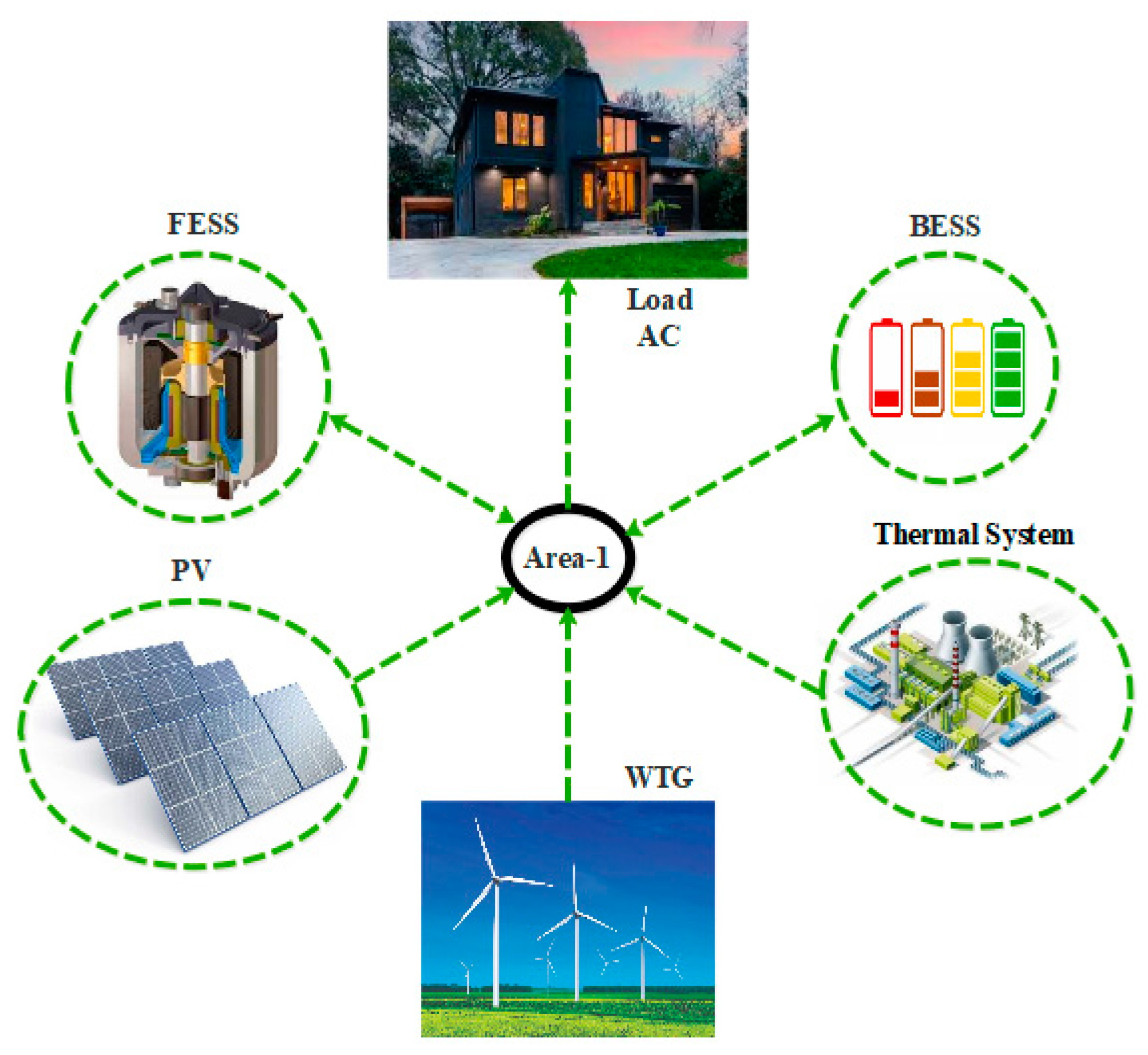
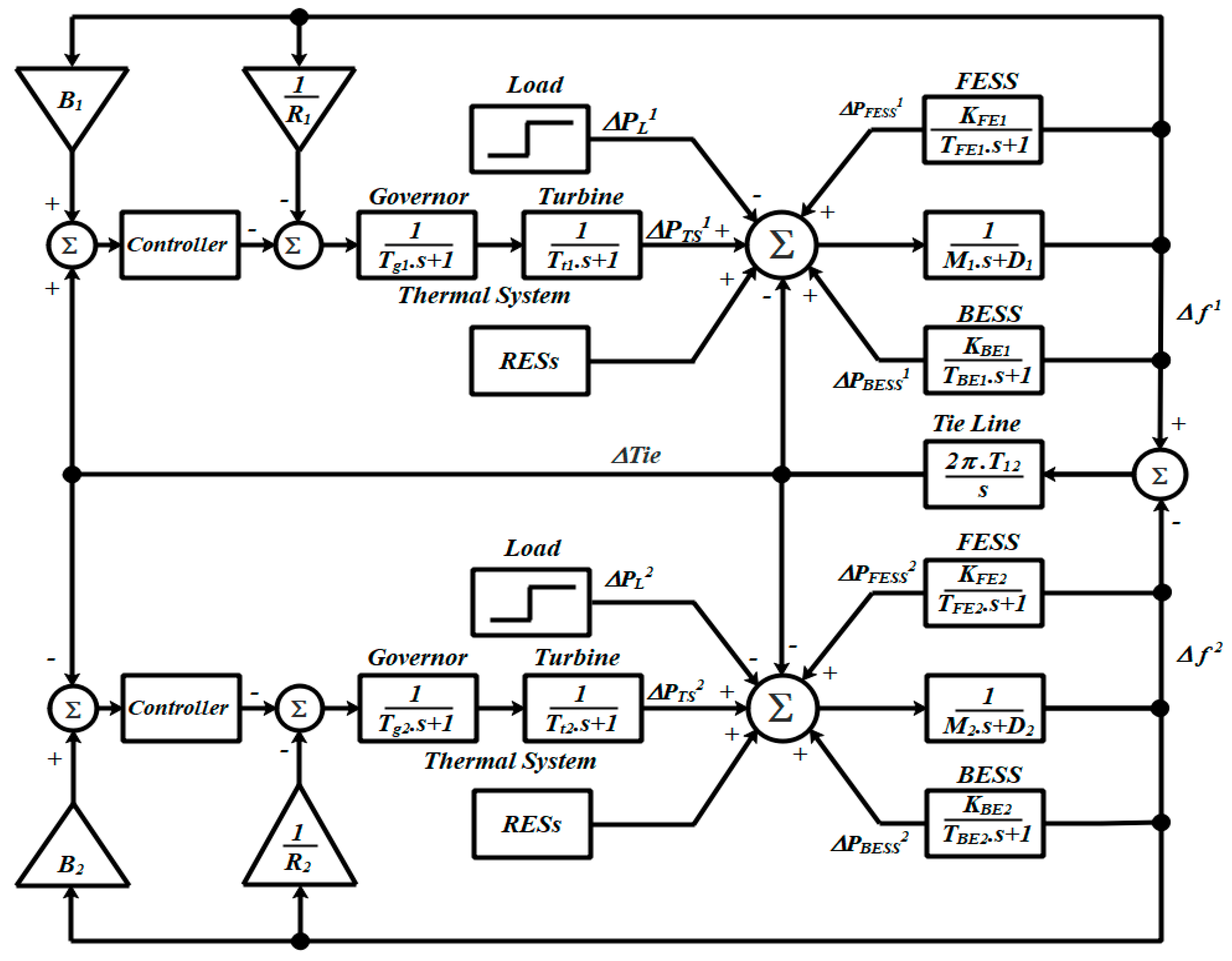
2. Two-Area Interconnected Power System

The studied two-area interconnected microgrid made up of two-area identical microgrids connected by a tie-line was taken into consideration for the investigation in this paper. A small thermal power plant, wind turbines (WT), photovoltaics (PV), FESS, BESS, and loads make up each microgrid. Figure 1 shows a schematic diagram of the studied two-area interconnected microgrid. The system’s parameters are listed in Table 1 and were extracted from the study in [34]. When there is a supply–demand imbalance, the synchronous generator (SG) frequently operates in the standby mode and is regulated by a secondary LFC. Storage units in each MG are controlled by frequency fluctuations in the corresponding regions; hence, an additional controller is not necessary to regulate ESS [34,35]. Figure 2 shows the transfer function model of the under-study two interconnected microgrids. A model of the RES transfer function for the system under study is also shown in Figure 3.

2.1. Thermal Power Plant Model

The SG can recognize changes in demand and limit fuel consumption by implementing the proper control mechanisms in a microgrid setting. The speed governor and turbine system make up this SG. The governor and the turbine can be modeled using a first-order transfer function [34,35]. The transfer function of the governor is denoted by:
G ( s ) G o v = 1 T g s + 1
The transfer function below describes the turbine:
G ( s ) T u r = 1 T t s + 1

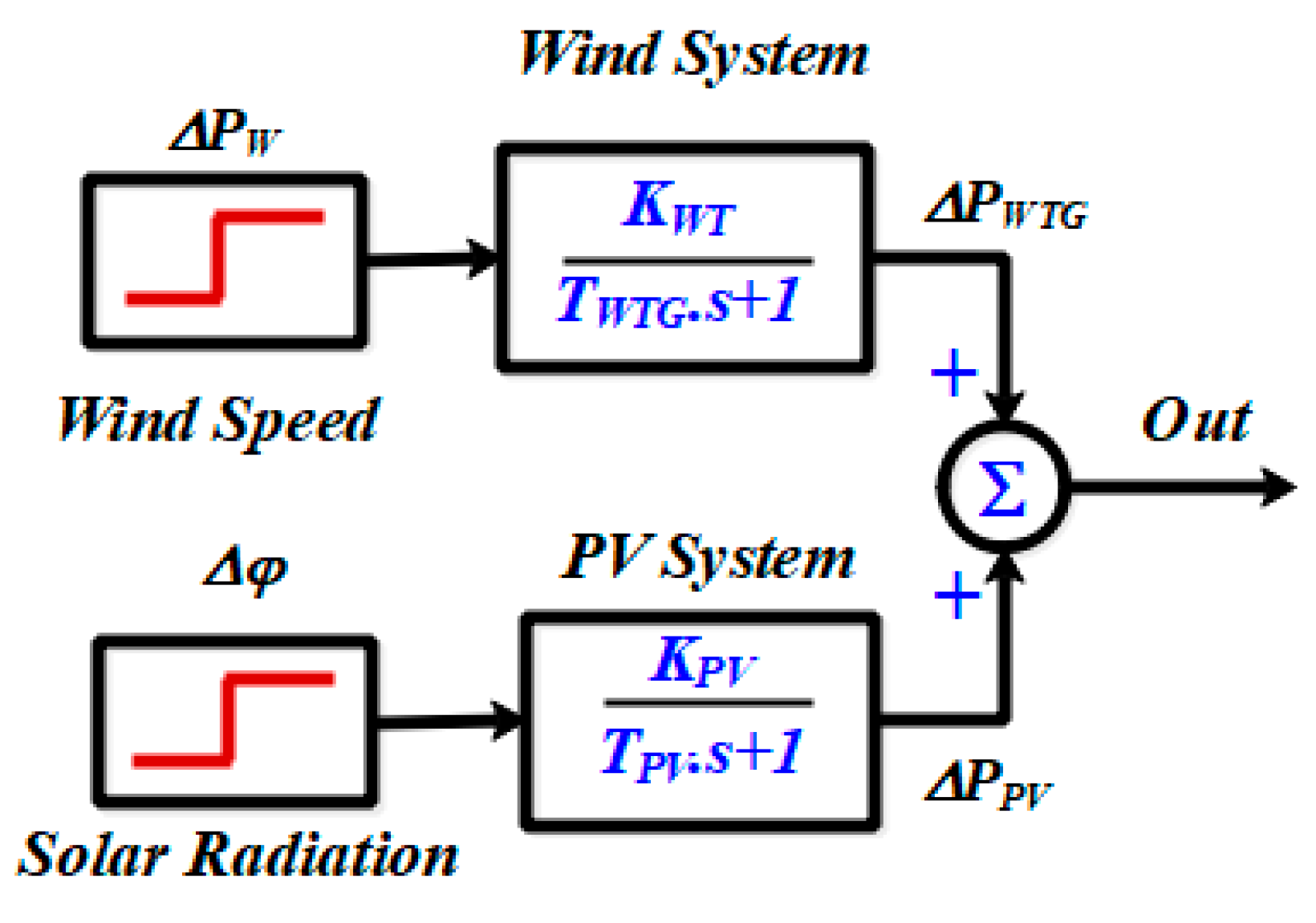
2.2. Wind Turbine Model

In the wind generation system, a wind turbine transforms the kinetic energy of vast quantities of air moving across the Earth’s surface into mechanical energy. The wind turbine is rotated using the kinetic energy received by the blades. The generator rotates in the same direction as the turbine, whether it is connected to it directly or indirectly using a gearbox. In light of this, the generator generates electricity following Faraday’s law. The fundamental idea underlying this is that kinetic energy is transformed into mechanical energy, which is then transformed into electrical energy. The output of a wind turbine generator is influenced by the wind speed, air density, and swept area of the rotor blades. The turbine output power is expressed in Equation (3):
P W T G = 1 2 A ρ C P V 3
where A is the rotor blades’ swept area in square meters, ρ   is the air density in kg/ m 2 , C P is the power coefficient, and V is the wind speed. To address the LFC difficulties, the wind turbine generator (WTG) was developed to meet the LFC challenges [36,37]. In Equation (4), the design of the wind power system is depicted as a transfer function.
G W T G ( s ) = P W T G ( s ) P W ( s ) = K W T T W T G s + 1

2.3. Photovoltaic Model

A solar PV system composed of many cells can function as a DG micro-source in a microgrid by converting infinite and unrestricted solar energy to electrical energy. The amount of electricity produced by a PV system depends on the cell’s surface area, the radiation’s intensity, and the ambient temperature [36,37]. The electricity used from the PV system is approximated using Equation (5).
P P V = γ . S . φ [ 1 0.005 ( T a + 25 ) ]
where S is the PV array area in m 2 , φ represents the solar irradiation in kW / m 2 , T a is ambient temperature, and γ is the conversion efficiency. The solar PV system’s transfer function can be expressed as shown in Equation (6).
G W T G ( s ) = P W T G ( s ) P W ( s ) = K W T T W T G s + 1

2.4. Energy Storage System

BESS and FESS are frequently ESSs utilized to avoid power supply interruptions in a microgrid because RESs are, by their very nature, intermittent. As a result, ESSs are crucial to the efficient running of microgrids. The BESS and FESS transfer functions are expressed in Equations (7) and (8), respectively.
G B E S S ( s ) = P B E ( s ) P E B i ( s ) = K B E T B E s + 1
G F E S S ( s ) = P F E ( s ) P F B i ( s ) = K F E T F E s + 1
The transfer function in Equation (9) can be used to describe the relationship between system frequency deviance and per unit power deviation.
G P ( s ) = 1 M i s + D i
where M and D are the system inertia and damping, respectively. i is the area number.

3. Proposed Control System

The main objectives of a controller designed for an AGC system are to swiftly push frequency and generation, and tie power variations to zero when subjected to a rapid or step load perturbation (SLP). As part of SLP, the controller is tasked with reducing the resultant area control error (ACE) to zero in each area as quickly as possible. Due to its straightforward design, dependable performance, low cost, and potential for use across engineering disciplines, the traditional PID controller is preferred by the majority of the microgrid industry. However, because of the extended microgrid’s inherent complexity, the existence of nonlinearities, the effects of uncertainties, and their combined effects, PID controllers are relatively ineffective at providing the necessary level of resilience and outcome in fluctuating operating conditions.
The proposed FOPIDA-FOIDN controller, on the other hand, has proven to be more adaptable and capable of overcoming the difficulties in microgrid control. The proposed FOPIDA-FOIDN controller is based on a fractional-order proportional-integral-derivative-accelerated (FOPIDA) controller in the feed-forward direction and a fractional-order integral-derivative with low-pass filter compensator (FOIDN) controller in the feedback direction, which is referred to as the FOPIDA-FOIDN controller. Moreover, the feed-forward controller (i.e., FOPIDA controller) is focused on processing and reducing the area control error signal, while the feedback controller (i.e., FOIDN controller) is focused on reducing the area frequency deviation. Furthermore, the robustness of the FOPIDA-FOIDN controller can be verified with different scenarios, and the transient response characteristics obtained using various controllers prove the supremacy of the proposed controller. Therefore, it can be inferred that the FOPIDA-FOIDN controller is more adaptable and capable of overcoming the difficulties in microgrid control. As a result, in this study, the proposed FOPIDA-FOIDN controller was applied as a knowledgeable, reliable, and intelligent controller for the AGC of a two-area interconnected hybrid microgrid. Figure 4 shows the structure of the proposed controller.
The proposed controller’s transfer function is expressed as follows:
A C E [ K p 11 + K i 11 S λ 11 + K d 11 S μ 11 + K a 11 S v 11 ] f [ K i 12 S λ 12 + N 11 K d 12 1 + S μ 12 N 11 ] = C o n t r o l   S i g n a l
Kp11, Ki11, Kd11, Ka11, Ki12, Kd12, and N11 limit the parameters of the controllers to values between [0–20]. Additionally, they set λ 11 ,   μ 11   , V 11 , λ 12   ,   and     μ 12 between values [0–1]. For the power system to operate more effectively in a variety of working situations, the FOPIDA-FOIDN controller metrics must be tuned to their optimum level. The dynamic changes in and uncertainty of the model can be managed by optimizing the proposed control system. The power system must follow each variable’s predicted point and be extremely sensitive to changes in load disturbance. Of all the performance metrics used to evaluate the effectiveness of the power system, ITAE was found to be the one that produces satisfactory results for parametric optimization based on settling time and overshoot. As a result, ITAE is considered to be the target function to be minimized in the proposed study. It is represented as follows, concerning a two-area interconnected microgrid:
I T A E = 0 T t   ( | f 1 | + | f 2 | + | P T i e | )   d t
where P T i e stands for the variation in power in the tie-line, f 1 represents frequency changes corresponding to the area (1), and f 2 stands for frequency changes related to area (2). The proposed HGTOEO algorithm approach for examining the FOPIDA-FOIDN controller parameters minimizes the objective function ITAE. A schematic diagram of the ITAE target function build is shown in Figure 5.

4. Optimization Technique

4.1. Artificial Gorilla Troops Optimizer

The AGTO mimics the lifestyle of the gorilla swarm in nature. Similar to other meta-heuristic optimization techniques, the GTO consists of two processes, including exploration and exploitation processes [31,32]. The silverback gorilla represents the best solution, while the locations of the gorillas and the candidate gorillas are known as X and G X , respectively. The phases of the GTO can be described as follows [38,39,40].

4.1.1. Exploration Phase

The exploitation phase of the GTO is based on three mechanisms, including the motion of gorillas to new areas, the motion of gorillas to known places, and the motion of gorillas to each other’s. An adjustable operator ( P ) is used for adjusting the transitions between these motions as follows:
G X ( t + 1 ) = ( U B L B ) × r 1 + L B                                                         I f   r a n d < p
G X ( t + 1 ) = ( r 2 C ) × X r ( t ) + L × H                                                                   I f   r a n d   0.5
X ( i ) L × ( L × ( X ( t ) G X r ( t ) ) + r 3 × ( X ( t ) G X r ( t ) ) )       I f   r a n d < 0.5
where
C = F × ( 1 t T M a x )
F = c o s ( 2 × r 4 ) + 1
L = C × l
H = Z × X ( t )
Z = [ C , C ]
where U B is the upper boundary of a control variable, while L B is the lower boundary. r 1 , r 2 , r 3 , and r 4 are random values in [0–1]. The value of l varies between −1 and 1.

4.1.2. Exploitation Phase

The male and female gorillas follow the silverback gorilla, which is the leader of the swarm, but when the silverback gorilla becomes old or dies, the young males or the back–back gorillas start fighting to obtain the females and the leadership. In the exploitation phase, two factors are used for adjusting the transition in this phase. If C W , the gorilla positions are updated as follows:
G X ( t + 1 ) = L × M × ( X ( t ) X silverback ) + X ( t )
M = ( | 1 N i = 1 N G X i ( t ) | g ) 1 8
g = 2 L
If C < W , the gorilla positions are updated as follows:
G X ( i ) = X silverback   ( X silverback   × Q X ( t ) × Q ) × A
Q = 2 × r 5 1
A = β × E
E = { N 1 ,           rand   0.5 N 2 ,           rand   < 0.5
r 5 is to a random number within [0–1]. β is a predefined value. E is a random value.

4.2. The Equilibrium Optimizer

The EO is a robust optimizer that simulates the balance of the control volume. The concentration in the dynamic equilibrium state represents the search agents. The following equation describes the balanced equation of the mass:
V d c d t = Q X e q Q X + G
where   V , Q , and X are the volume, the flow rate, and the concentration, respectively.
X = X e q + ( C 0 C e q ) exp [ λ ( t e 0 ) ] + G λ V   ( 1 ( exp [ λ ( t e 0 ) ] ) )
where λ = ( Q V ) .   X 0 and   e 0 are the initial concentration and the starting time. A vector pool ( X p o o l ) is constructed in the EO technique, which consists of the best four solutions as well as their average solution as follows:
X a v g = X 1 + X 2 + X 3 + X 4 4
X p o o l = { X 1 , X 2   , X 3 , X 4   ,   X a v g }
The main equation of the EO is formulated as follows:
X = X p o o l + ( X X p o o l ) .   F + G λ V ( 1 F )
where
F = a 1 s i g n ( r 0.5 ) [ e λ e 1 ]
e o = ( 1 T T M a x   ) (   a 2   T T M a x )                
G = G 0   e k ( e e 0 )
G 0 = G C P   ( X p o o l   λ X )
G C P =             { 0.5   r 1         r 2 G P 0                     r 2 < G P
where r and λ are two vectors that are generated randomly. a 1 and a 2 are two constant values that were selected to be to be 2 and 1, respectively. r 1 and r 2 are random parameters in the range of [0–1]. GP is a constant value that was selected to be 0.5. The final step in the EO is memory-saving where the generated solution is compared to the old solution, and it is updated if the new solution is better.
The main limitations of the GTO are its tendency to local optima and suffering from stagnation. In this regard, for improving the searching ability of the conventional GTO, its exploitation and exploration phases are combined with the exploitation and exploration methodologies of the EO technique. The presented HGTOEO aims to combine the GTO and the EO, as depicted in Figure 6. The proposed efficient hybrid GTOEO has an excellent performance and searching ability, where the exploration process combines three exploration operators of the GTO (i.e., motion to an unknown place, motion towards a known placement, and motion to the other gorillas) as well as the exploration technique of the EO (i.e., a particle’s memory-saving approach). In addition, the proposed hybrid algorithm combines the exploitation methodologies of the GTO and the EO, including the motion of the particles (gorillas) concerning the best solution (silverback) and the concentration updating in EO. It should be highlighted that t represents the current iteration of the optimization process. This process is repeated until the stopping criteria are satisfied (i.e., the current iteration equals the maximum number of iterations).
The computational complexity of the proposed hybrid GTOEO is based on the computational complexities of the EO and the GTO. In general, the computational complexity is the dimension of the problem (d), the iteration number (t), the number of population (n), and the cost function. The computational complexity of EO is based on the initialization, function evaluation, memory saving, and concentration Update, which can be calculated as follows:
O ( E O ) = O   ( 1 + n d + t c n + t n + t n d )   = O   ( t n d + t c n )
The computational complexity of GTO is based on its exploitation and exploration phases, which can be described as follows:
O ( G T O ) = O ( n × ( 1 + t + t d ) × 2 )
Thus, the computational complexity of the hybrid GTOEO can be calculated as follows:
O   ( G T O E O ) = O ( n × ( 2 + 2 t + 3 t d + t c ) )

5. Results and Discussion

The simulated model of the chosen test system was created using MATLAB (R2019b) software on a Core i5 computer with 8 GB of RAM. Table 1 contains a list of the test system parameters. Several other strategies from the literature were compared to the effectiveness of the proposed coordinated strategy. Additionally, under a variety of difficult operating conditions, the performance of the chosen HGTOEO algorithm was compared with those of several other algorithms in the literature, including GA, JAYA, IJAYA, MVO, and CMVO based on the PID controller.

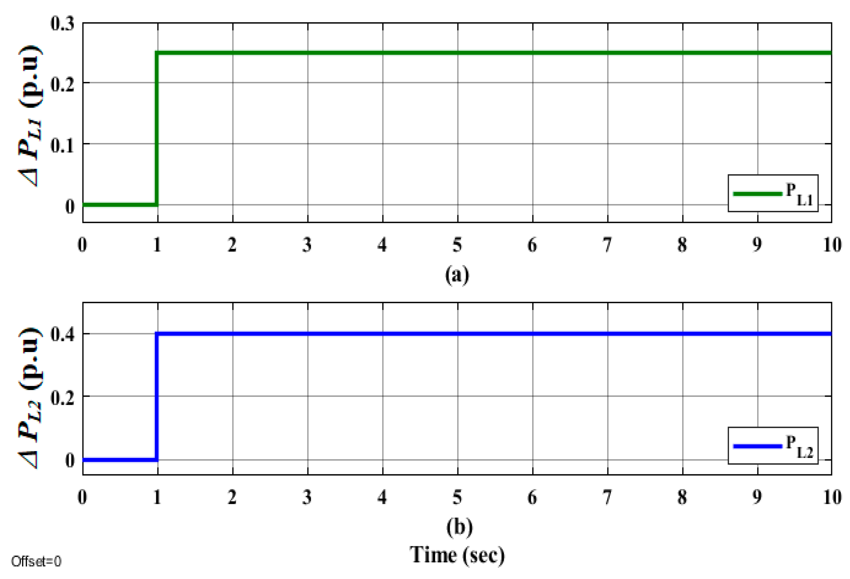
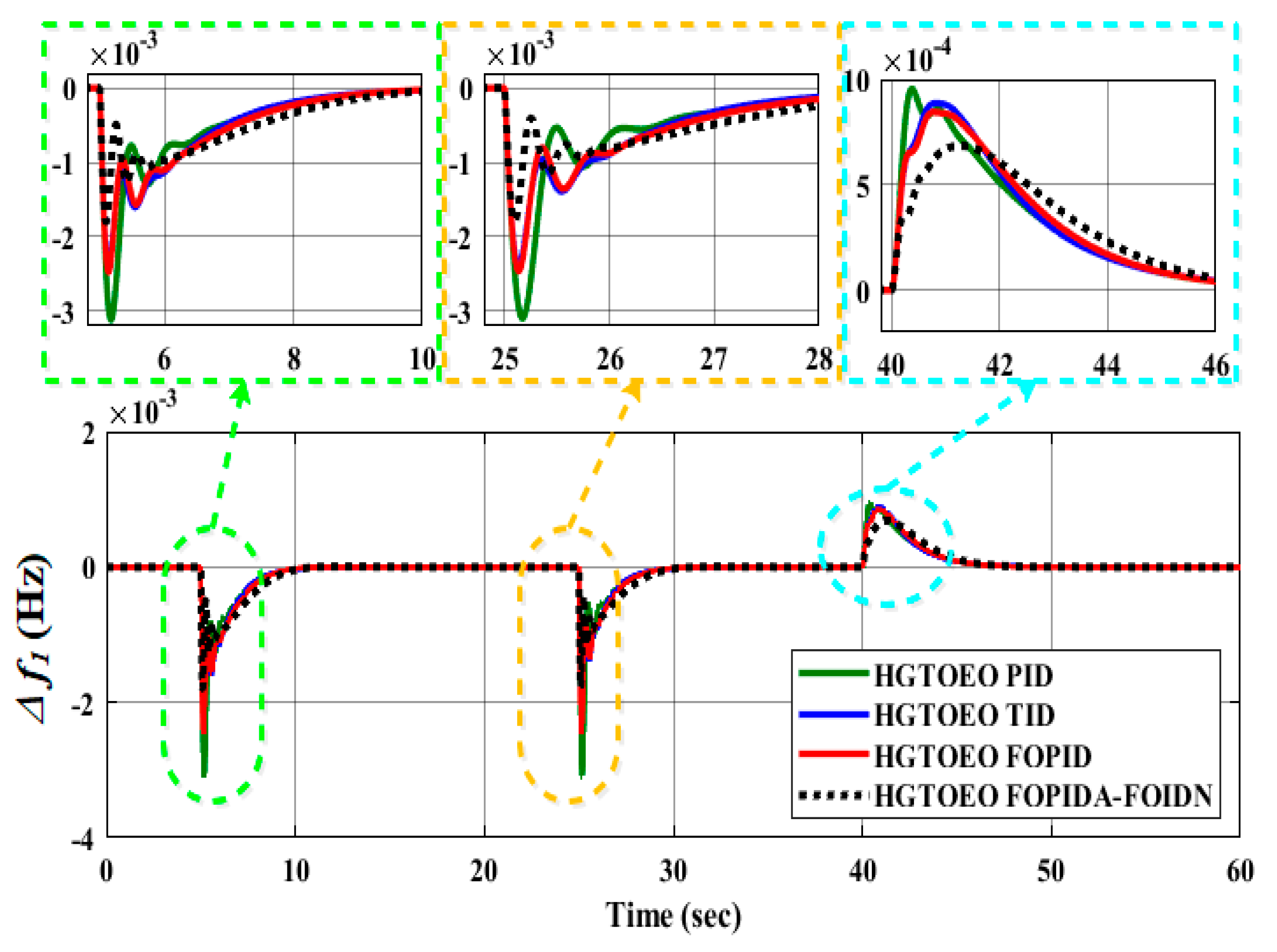
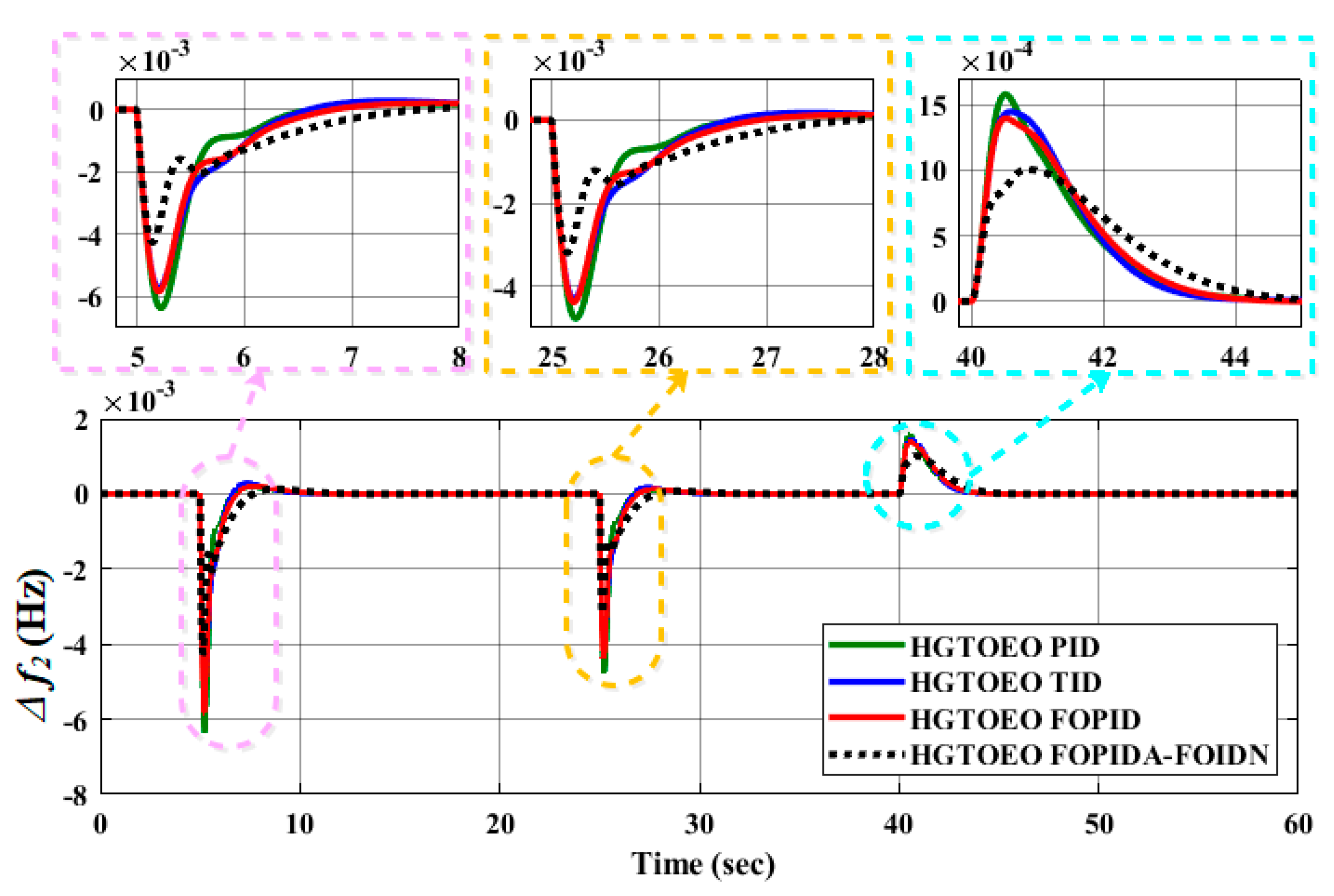
5.1. System Performance Evaluation under SLP

The first scenario accounts for step fluctuations in load, wind, and solar irradiation. The load demand, wind turbine power output, and solar photovoltaic power output are shown in Figure 7. (PPV). To test the efficacy of the proposed HGTOEO technique, a PID controller was primarily controlled using GA, JAYA, IJAYA, MVO, and CMVO, and then a more visible comparative analysis with HGTOEO. When HGTOEO was used to tune the PID with ITAE objective function for step disturbance, the tuned PID values with ITAE values were obtained, as shown in Table 2. For comparison’s sake, Table 2 also includes the ITAE and PID values obtained in other published techniques [34,35]. The load demand (PL), wind turbine, and solar PV production (PWind and PPV) depicted in Figure 7 produced step changes. Table 3 presents the final best-tuned parameters for HGTOEO-PID. Frequency deviations in area_1 (Δf1) are shown as in Figure 8; frequency deviations in area_2 (Δf2) are shown in Figure 9; and deviations in the tie-line power (ΔPtie) are shown in Figure 10.
The ITAE value of HGTOEO (0.1036) is lower than those from GA, JAYA, IJAYA, MVO, and CMVO-based PIDs. The best final solutions were chosen as the controller parameters after the algorithms were run more than 30 times. The variations in Δf1, Δf2, and ΔPtie during these disturbances are depicted in Figure 8, Figure 9, and Figure 10, respectively. The outcomes demonstrate that the suggested HGTOEO-PID controller’s dynamic reaction is superior to that of the GA, JAYA, IJAYA, MVO, and CMVO based on the PID controller. The HGTOEO-PID controller showed a fast-settling time and minor deviations in Δf1, Δf2, and ΔPtie.
A step change in the load was provided without regard to any interference of renewable energy sources, such as wind and solar radiation, as shown in Figure 11. This scenario, as shown in Figure 11, compared the performance of the proposed FOPIDA-FOIDN controllers with the FOPID, TID, and PID controllers after selecting their gains using the HGTOEO method while applying 25% SLP to area-1 and 40% SLP to area-2. This was conducted as part of a robustness analysis of the proposed FOPIDA-FOIDN controllers. Δf1 in area-1 is shown in Figure 12a; Δf2 in area-2 is shown in Figure 12b; and deviations in the ΔPtie are shown in Figure 12c. Moreover, the TID convergence characteristics outperform those of the FOPID. Compared to the FOPID and TID, the FOPIDA-FOIDN controller achieves better system responses. Particularly in terms of undershoot, settling time, and convergence characteristics, the suggested FOPIDA-FOIDN controller continues to offer the best system responses. Additionally, the results demonstrate that the PID-based LFC is the worst. Figure 12 displays the simulated transient responses for the line power and frequency variations using the FOPIDA-FOIDN controllers. From the analysis of Figure 12, it can be observed that an improved performance with less overshoot and less settling time is obtained with the proposed controller parameters, as shown in Table 3, and set through the HGTOEO optimization algorithm with the ITAE objective function, as shown in Figure 5.

5.2. Second Scenario (Step Change in Load)

A step change in the load was provided without regard to any interference of renewable energy sources, such as wind and solar radiation, as shown in Figure 11. This scenario, as shown in Figure 11, compared the performance of the proposed FOPIDA-FOIDN controllers with the FOPID, TID, and PID controllers after selecting their gains using the HGTOEO method while applying 25% SLP to area-1 and 40% SLP to area-2. This was conducted as part of a robustness analysis of the proposed FOPIDA-FOIDN controllers. Δf1 in area-1 is shown in Figure 12a; Δf2 in area-2 is shown in Figure 12b; and deviations in the ΔPtie are shown in Figure 12c. Moreover, the TID convergence characteristics outperform those of the FOPID. Compared to the FOPID and TID, the FOPIDA-FOIDN controller achieves better system responses. Particularly in terms of undershoot, settling time, and convergence characteristics, the suggested FOPIDA-FOIDN controller continues to offer the best system responses. Additionally, the results demonstrate that the PID-based LFC is the worst. Figure 12 displays the simulated transient responses for the line power and frequency variations using the FOPIDA-FOIDN controllers. From the analysis of Figure 12, it can be observed that an improved performance with less overshoot and less settling time is obtained with the proposed controller parameters, as shown in Table 3, and set through the HGTOEO optimization algorithm with the ITAE objective function, as shown in Figure 5.

5.3. Third Scenario (Robustness to Parameters Change)

As illustrated in Figure 13, in this scenario, a random step increases and decreases the demand, and starting in the 40 s interval, a random step boosts renewable energy by 15% in two places. For each controller, Figure 14, Figure 15 and Figure 16 show the related variations in Δf1, Δf2, and ΔPtie during these disturbances. With the least frequency deviations and settling durations for all load changes, the proposed FOPIDA-FOIDN controller provides the highest performance for all load changes. The PID controller exhibits the lowest performance with the largest frequency deviations and settling time, while the two controllers, FOPID and TID, provide a satisfactory performance.

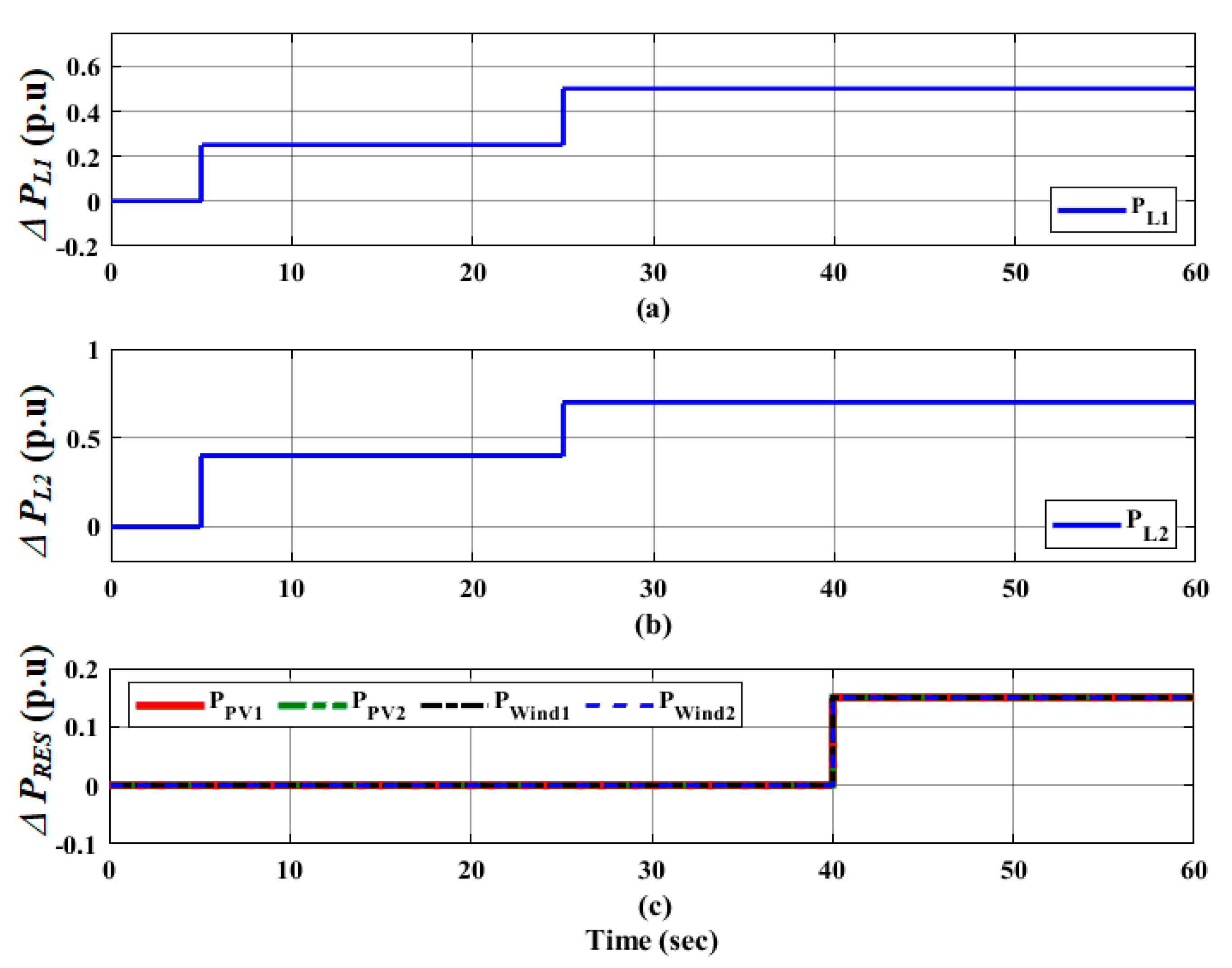
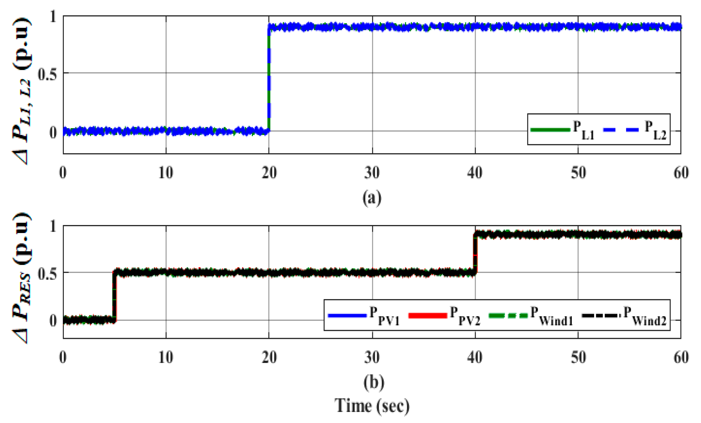
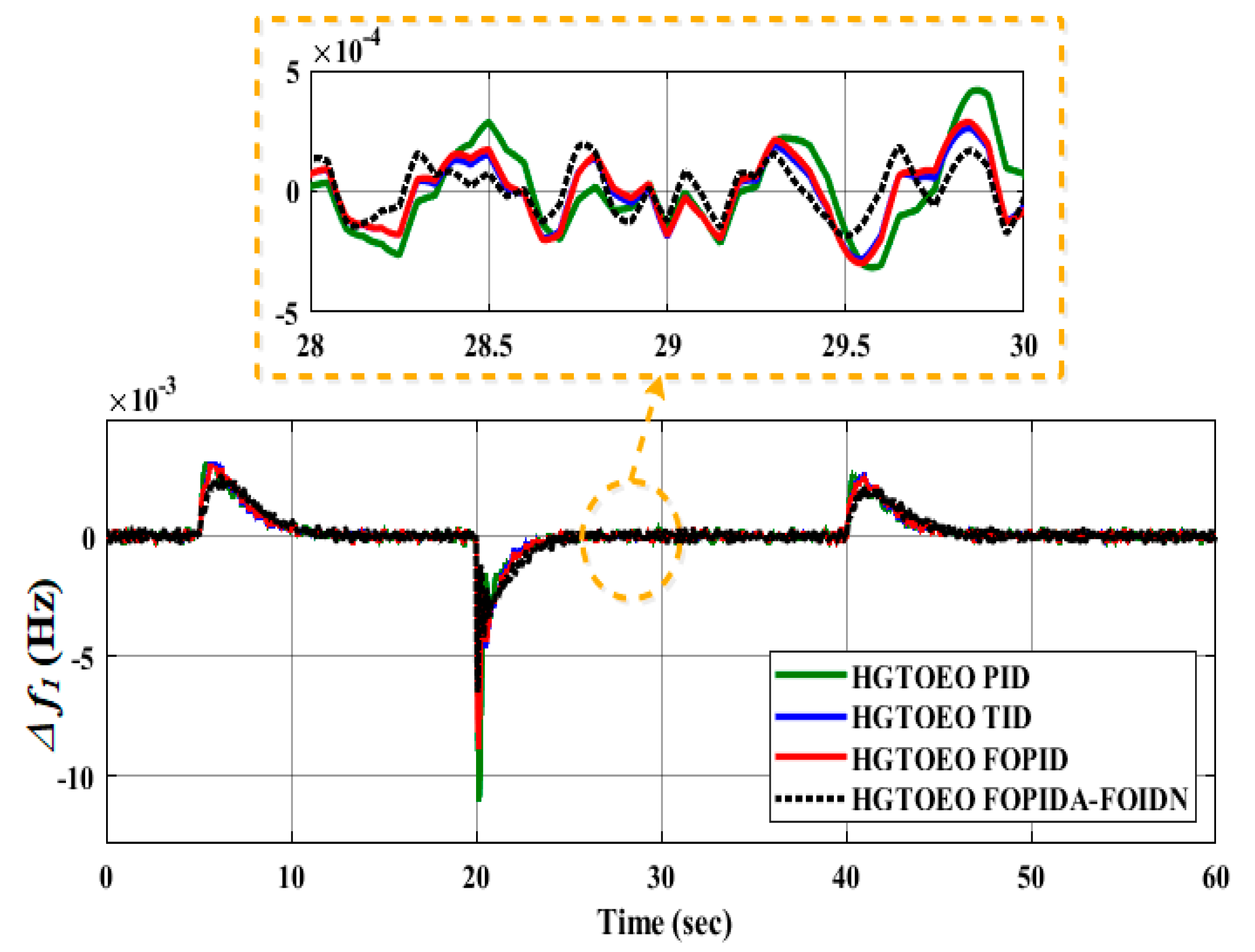
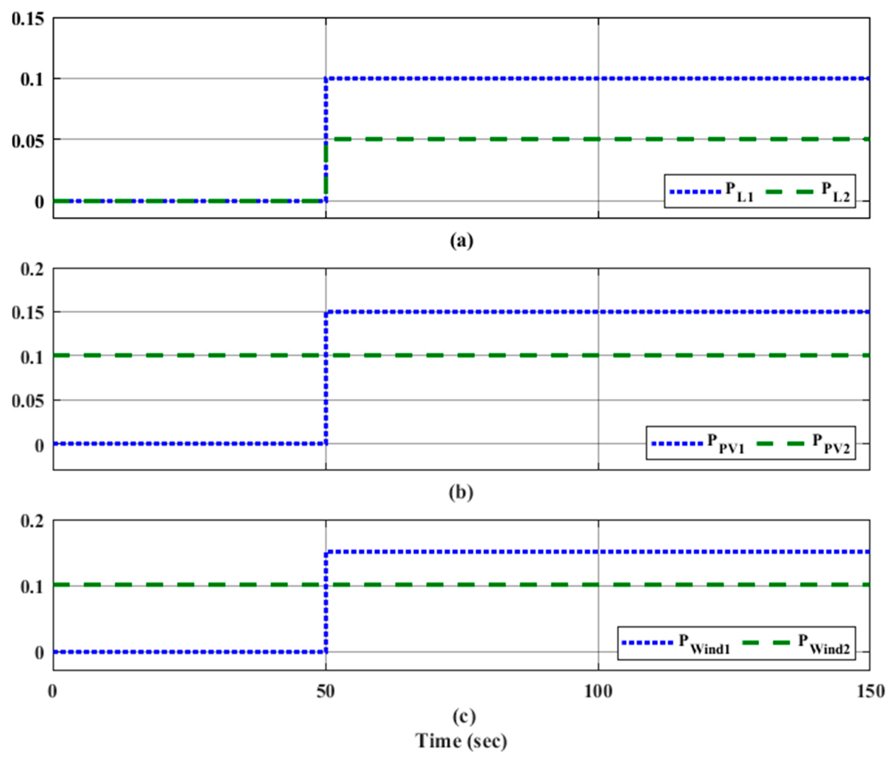
5.4. Fourth Scenario (The Random Step Change in Load and RESs)

The microgrid may experience significant swings in load demand and the generated power as a result of the high penetration of erratic and intermittent RESs. Therefore, in this scenario, both the load demand and large variations of intermittent RESs were studied. The considered variations of RES-generated power and load demand are depicted in Figure 17. The suggested FOPIDA-FOIDN controller is shown in Figure 18, Figure 19 and Figure 20 together with the matching dynamic response of the FOPID, TID, and PID controllers.
The fluctuations in Δf1, Δf2, and ΔPtie performance of the FOPIDA-FOIDN controller for the frequency stability of the microgrid are shown in Figure 18, Figure 19 and Figure 20, respectively. In all of the study situations, the results demonstrate that the suggested optimal FOPIDA-FOIDN controller, based on the HGTOEO algorithm, can achieve a better performance than FOPID, TID, and PID controllers when there are substantial variations in the generation of RESs.
Additionally, the participation of the Flywheel for the ESS and BESS in the microgrid’s frequency regulation can lessen the frequency deviation brought on by a significant change in the generation of RESs.

6. Conclusions

The proposed FOPIDA-FOIDN controller was designed as a FOPIDA controller in the feed-forward direction and a FOIDN controller in the feedback direction to enhance the frequency dynamic performance of the studied two-area interconnected microgrid. The parameters of the proposed controllers were selected using the proposed hybrid optimization algorithm, called HGTOEO, i.e., a combination of GTO and EO algorithms. Moreover, the proposed FOPIDA-FOIDN controller based on HGTOEO was tested and its performance was compared with the performance of the known controllers used in the literature, such as PID, TID, and FOPID, under different scenarios. The simulation results performed by the MATLAB software demonstrate that the proposed HGTOEO algorithm outperforms the previous powerful optimization algorithms, e.g., GA, JAYA, IJAYA, MVO, and CMVO. Additionally, the proposed FOPIDA-FOIDN controller outperformed the previously used FOPID, TID, and PID controllers in the frequency regulation of the studied two-area interconnected microgrid considering high RES penetration. Future work will focus on coordinating renewable energy sources with appropriate energy storage systems to enhance the dynamic stability of modern power systems. Moreover, robust control techniques will be appliede to the frequency control of renewable power systems.

Author Contributions

Conceptualization, M.E., G.M., S.C.G. and A.A.M.; Methodology, N.M.A., A.S.M.M. and A.A.M.; Software, M.E. and G.M.; Validation, K.S.; Formal analysis, N.M.A., M.E. and A.A.M.; Investigation, G.M.; Resources, M.E. and G.M.; Data curation, K.S.; Writing—original draft, N.M.A. and A.A.M.; Writing—review & editing, M.E., G.M., K.S., S.C.G. and A.S.M.M. All authors have read and agreed to the published version of the manuscript.

Funding

This work was funded by the Researchers Supporting Project number (RSP2023R363), King Saud University, Riyadh, Saudi Arabia.

Conflicts of Interest

The authors declare no conflict of interest.

References

  1. Hassan, S.M.U.; Ramli, M.A.M.; Milyani, A.H. Robust Load Frequency Control of Hybrid Solar Power Systems Using Optimization Techniques. Front. Energy Res. 2022, 10, 902776. [Google Scholar] [CrossRef]
  2. Mohan, A.M.; Meskin, N.; Mehrjerdi, H. A Comprehensive Review of the Cyber-Attacks and Cyber-Security on Load Frequency Control of Power Systems. Energies 2020, 13, 3860. [Google Scholar] [CrossRef]
  3. Kalyan, C.H.N.S.; Rao, G.S. Impact of communication time delays on combined LFC and AVR of a multi-area hybrid system with IPFC-RFBs coordinated control strategy. Prot. Control Mod. Power Syst. 2021, 6, 7. [Google Scholar] [CrossRef]
  4. Ahmed, N.M.; Ebeed, M.; Alhejji, A.; Refai, A. A Robust Cascaded Controller for Load Frequency Control in Renewable Energy Integrated Microgrid Containing PEV. Int. J. Renew. Energy Res. 2023, 13, 423–433. [Google Scholar] [CrossRef]
  5. Ranjan, M.; Shankar, R. A literature survey on load frequency control considering renewable energy integration in power system: Recent trends and future prospects. J. Energy Storage 2022, 45, 103717. [Google Scholar] [CrossRef]
  6. Annamraju, A.; Nandiraju, S. Robust frequency control in a renewable penetrated power system: An adaptive fractional order-fuzzy approach. Prot. Control Mod. Power Syst. 2019, 4, 16. [Google Scholar] [CrossRef]
  7. Annamraju, A.; Nandiraju, S. Coordinated control of conventional power sources and PHEVs using jaya algorithm optimized PID controller for frequency control of a renewable penetrated power system. Prot. Control Mod. Power Syst. 2019, 4, 28. [Google Scholar] [CrossRef]
  8. Nour, M.; Magdy, G.; Chaves-Ávila, J.P.; Sánchez-Miralles, Á.; Jurado, F. A new two-stage controller design for frequency regulation of low-inertia power system with virtual synchronous generator. J. Energy Storage 2023, 62, 106952. [Google Scholar] [CrossRef]
  9. Singh, B.; Slowik, A.; Bishnoi, S.K. A Dual-Stage Controller for Frequency Regulation in a Two-Area Realistic Diverse Hybrid Power System Using Bull–Lion Optimization. Energies 2022, 15, 8063. [Google Scholar] [CrossRef]
  10. Naderipour, A.; Abdul-Malek, Z.; Davoodkhani, I.F.; Kamyab, H.; Ali, R.R. Load-frequency control in an islanded microgrid PV/WT/FC/ESS using an optimal self-tuning fractional-order fuzzy controller. Environ. Sci. Pollut. Res. 2021, 30, 71677–71688. [Google Scholar] [CrossRef]
  11. Yildiz, S. An Autonomous Frequency Control Mechanism for Multi-Area Microgrids Incorporating with Distributed Energy Resources. Res. Sq. 2022. [Google Scholar] [CrossRef]
  12. Magdy, G.; Mohamed, E.A.; Shabib, G.; Elbaset, A.A.; Mitani, Y. SMES based a new PID controller for frequency stability of a real hybrid power system considering high wind power penetration. IET Renew. Power Gener. 2018, 12, 1304–1313. [Google Scholar] [CrossRef]
  13. Magdy, G.; Shabib, G.; Elbaset, A.A.; Mitani, Y. Optimized coordinated control of LFC and SMES to enhance frequency stability of a real multi-source power system considering high renewable energy penetration. Prot. Control Mod. Power Syst. 2018, 3, 39. [Google Scholar] [CrossRef]
  14. Magdy, G.; Bakeer, A.; Nour, M.; Petlenkov, E. A New Virtual Synchronous Generator Design Based on the SMES System for Frequency Stability of Low-Inertia Power Grids. Energies 2020, 13, 5641. [Google Scholar] [CrossRef]
  15. Magdy, G.; Mohamed, E.A.; Shabib, G.; Elbaset, A.A.; Mitani, Y. Microgrid dynamic security considering high penetration of renewable energy. Prot. Control Mod. Power Syst. 2018, 3, 23. [Google Scholar] [CrossRef]
  16. Ali, H.H.; Fathy, A.; Al-Shaalan, A.M.; Kassem, A.M.; Farh, H.M.H.; Al-Shamma’a, A.A.; Gabbar, H.A. A Novel Sooty Terns Algorithm for Deregulated MPC-LFC Installed in Multi-Interconnected System with Renewable Energy Plants. Energies 2021, 14, 5393. [Google Scholar] [CrossRef]
  17. Kumar, A.; Kumari, N.; Shankar, G.; Elavarasan, R.M.; Kumar, S.; Srivastava, A.K.; Khan, B. Load Frequency Control of Distributed Generators Assisted Hybrid Power System Using QOHSA Tuned Model Predictive Control. IEEE Access 2022, 10, 109311–109325. [Google Scholar] [CrossRef]
  18. Latif, A.; Das, D.C.; Barik, A.K.; Ranjan, S. Illustration of demand response supported co-ordinated system performance evaluation of YSGA optimized dual stage PIFOD-(1 + PI) controller employed with wind-tidal-biodiesel based independent two-area interconnected microgrid system. IET Renew. Power Gener. 2020, 14, 1074–1086. [Google Scholar] [CrossRef]
  19. Khan, I.A.; Mokhlis, H.; Mansor, N.N.; Illias, H.A.; Awalin, L.J.; Wang, L. New trends and future directions in load frequency control and flexible power system: A comprehensive review. Alex. Eng. J. 2023, 71, 263–308. [Google Scholar] [CrossRef]
  20. Kumar, S.; Anwar, N. Fractional order PID Controller design for Load Frequency Control in Parallel Control Structure. In Proceedings of the 2019 54th International Universities Power Engineering Conference (UPEC), Bucharest, Romania, 3–6 September 2019; pp. 1–6. [Google Scholar] [CrossRef]
  21. Choudhary, A.K.; Prakash, S.; Sharma, M.; Dhundhara, S. Grasshopper optimisation based robust power/frequency regulator for shipboard micro-grid. IET Renew. Power Gener. 2020, 14, 3568–3577. [Google Scholar] [CrossRef]
  22. Abdel-Hamed, A.M.; Abdelaziz, A.Y.; El-Shahat, A. Design of a 2DOF-PID Control Scheme for Frequency/Power Regulation in a Two-Area Power System Using Dragonfly Algorithm with Integral-Based Weighted Goal Objective. Energies 2023, 16, 486. [Google Scholar] [CrossRef]
  23. Gulzar, M.M.; Murawwat, S.; Sibtain, D.; Shahid, K.; Javed, I.; Gui, Y. Modified Cascaded Controller Design Constructed on Fractional Operator ‘β’ to Mitigate Frequency Fluctuations for Sustainable Operation of Power Systems. Energies 2022, 15, 7814. [Google Scholar] [CrossRef]
  24. Chen, M.-R.; Zeng, G.-Q.; Dai, Y.-X.; Lu, K.-D.; Bi, D.-Q. Fractional-Order Model Predictive Frequency Control of an Islanded Microgrid. Energies 2018, 12, 84. [Google Scholar] [CrossRef]
  25. Gheisarnejad, M.; Khooban, M.-H.; Dragicevic, T. The Future 5G Network-Based Secondary Load Frequency Control in Shipboard Microgrids. IEEE J. Emerg. Sel. Top. Power Electron. 2019, 8, 836–844. [Google Scholar] [CrossRef]
  26. Sabahi, K.; Tavan, M.; Hajizadeh, A. Adaptive type-2 fuzzy PID controller for LFC in AC microgrid. Soft Comput. 2021, 25, 7423–7434. [Google Scholar] [CrossRef]
  27. Badavath, S.; Rai, A.; Das, D.K. Class Topper Optimization based Fuzzy-PI Controller Design to Solve Load Frequency Control in Microgrids. In Proceedings of the 2021 International Symposium of Asian Control Association on Intelligent Robotics and Industrial Automation (IRIA), Goa, India, 20–22 September 2021; pp. 113–118. [Google Scholar] [CrossRef]
  28. Golkhandan, R.K.; Torkaman, H.; Aghaebrahimi, M.R.; Keyhani, A. Load frequency control of smart isolated power grids with high wind farm penetrations. IET Renew. Power Gener. 2020, 14, 1228–1238. [Google Scholar] [CrossRef]
  29. Bhullar, A.K.; Kaur, R.; Sondhi, S. Design of FOPID Controller for Optimizing AVR System using Neural Network Algorithm. In Proceedings of the 2020 IEEE 17th India Council International Conference (INDICON), New Delhi, India, 10–13 December 2020; pp. 1–7. [Google Scholar] [CrossRef]
  30. Fathy, A.; Kassem, A.M. Antlion optimizer-ANFIS load frequency control for multi-interconnected plants comprising photovoltaic and wind turbine. ISA Trans. 2018, 87, 282–296. [Google Scholar] [CrossRef]
  31. Karimipouya, A.; Karimi, S.; Abdi, H. Microgrid frequency control using the virtual inertia and ANFIS-based Controller. Int. J. Ind. Electron. Control Optim. 2019, 2, 145–154. [Google Scholar] [CrossRef]
  32. Akula, S.K.; Salehfar, H. Frequency Control in Microgrid Communities Using Neural Networks. In Proceedings of the 2019 North American Power Symposium (NAPS), Wichita, KS, USA, 13–15 October 2019; pp. 1–6. [Google Scholar] [CrossRef]
  33. Wang, H.; Wang, Z.; Sun, Y.; Guo, Y.; Fang, C.; Li, M.; Sun, Y. Optimal Control Design for Load Frequency Control with Network-induced Delays. In Proceedings of the 2020 IEEE 3rd International Conference on Electronic Information and Communication Technology (ICEICT), Shenzhen, China, 13–15 November 2020; pp. 664–669. [Google Scholar] [CrossRef]
  34. Gheisarnejad, M.; Khooban, M.H. Secondary load frequency control for multi-microgrids: HiL real-time simulation. Soft Comput. 2018, 23, 5785–5798. [Google Scholar] [CrossRef]
  35. Sahoo, B.P.; Panda, S. Chaotic multi verse optimizer based fuzzy logic controller for frequency control of microgrids. Evol. Intell. 2021, 14, 1597–1618. [Google Scholar] [CrossRef]
  36. Mahto, T.; Malik, H.; Mukherjee, V.; Alotaibi, M.A.; Almutairi, A. Renewable generation based hybrid power system control using fractional order-fuzzy controller. Energy Rep. 2021, 7, 641–653. [Google Scholar] [CrossRef]
  37. Ali, M.; Kotb, H.; AboRas, M.K.; Abbasy, H.N. Frequency regulation of hybrid multi-area power system using wild horse optimizer based new combined Fuzzy Fractional-Order PI and TID controllers. Alex. Eng. J. 2022, 61, 12187–12210. [Google Scholar] [CrossRef]
  38. Sayed, G.I.; Hassanien, A.E. A Novel Chaotic Artificial Gorilla Troops Optimizer and Its Application for Fundus Images Segmentation. In Proceedings of the International Conference on Advanced Intelligent Systems and Informatics 2021, Cairo, Egypt, 11–13 December 2021; Hassanien, A.E., Snášel, V., Chang, K.C., Darwish, A., Gaber, T., Eds.; Springer International Publishing: Berlin/Heidelberg, Germany, 2022; pp. 318–329. [Google Scholar]
  39. Ginidi, A.; Ghoneim, S.M.; Elsayed, A.; El-Sehiemy, R.; Shaheen, A.; El-Fergany, A. Gorilla Troops Optimizer for Electrically Based Single and Double-Diode Models of Solar Photovoltaic Systems. Sustainability 2021, 13, 9459. [Google Scholar] [CrossRef]
  40. Abdollahzadeh, B.; Gharehchopogh, F.S.; Mirjalili, S. Artificial gorilla troops optimizer: A new nature-inspired metaheuristic algorithm for global optimization problems. Int. J. Intell. Syst. 2021, 36, 5887–5958. [Google Scholar] [CrossRef]
Figure 1. A schematic diagram of the studied microgrid system.
Fractalfract 07 00666 g001
Figure 2. Block diagram of the two−area interconnected microgrid under study.
Fractalfract 07 00666 g002
Figure 3. Renewable energy model for the system under study.
Fractalfract 07 00666 g003
Figure 4. Structure of the proposed FOPIDA−FOIDN controller.
Fractalfract 07 00666 g004
Figure 5. A schematic diagram for the construction of the ITAE objective function.
Fractalfract 07 00666 g005
Figure 6. Flowchart of the proposed HGTOEO algorithm.
Fractalfract 07 00666 g006
Figure 7. A step change in load demand and power generated from WTG and PV in the first scenario.
Fractalfract 07 00666 g007
Figure 8. System response to the first scenario, Δf1 deviation.
Fractalfract 07 00666 g008
Figure 9. System response to the first scenario, Δf2 deviation.
Fractalfract 07 00666 g009
Figure 10. System response to the first scenario, ΔPtie deviation.
Fractalfract 07 00666 g010
Figure 11. A step change in the load demand in PL1 and PL2.
Fractalfract 07 00666 g011
Figure 12. System response to the second scenario, Δf1, Δf2, and ΔPtie deviations.
Fractalfract 07 00666 g012
Figure 13. Stochastic variation of the load demand, PV, and wind-generated power of area−1 and area−2.
Fractalfract 07 00666 g013
Figure 14. System response to the third scenario, Δf1 deviations.
Fractalfract 07 00666 g014
Figure 15. System response to the third scenario, Δf2 deviations.
Fractalfract 07 00666 g015
Figure 16. System response to the third scenario, ΔPtie deviations.
Fractalfract 07 00666 g016
Figure 17. Stochastic fluctuation of load demand, PV, and wind-generated power in area-1 and area-2.
Fractalfract 07 00666 g017
Figure 18. System response to the fourth scenario, Δf1 deviations.
Fractalfract 07 00666 g018
Figure 19. System response to the fourth scenario, Δf2 deviations.
Fractalfract 07 00666 g019
Figure 20. System response to the fourth scenario, ΔPtie deviations.
Fractalfract 07 00666 g020
Table 1. Values of the investigated system’s parameters.
ParameterDescriptionArea (1)Area (2)
T g Speed governor time constant (s)0.10.1
K g Governor gain constant (p.u.)11
T t Time constant of the turbine (s)0.40.4
K T Turbine gain constant (p.u.)11
R Speed regulation constant (p.u.)0.050.04
B Frequency bias constant (p.u.)1012.5
M 2 Inertia constant (p.u.)88
D 2 Damping constant (p.u.)11
K P V Gain constant of PV (p.u.)11
K W T Gain constant of WT (p.u.)11
T P V Time constant of PV (s)1.51.5
T W T Time constant of WT (s)0.50.5
K B E Gain constant of BESS (p.u.)−3−4
T B E Time constant of BESS (s)0.10.1
K F E Gain constant of FESS (p.u.)−1.5−2
T F E Time constant of FESS (s)0.10.1
T 12 Synchronizing coefficient0.70.7
Table 2. The optimal parameters of the designed PID controller-based different optimization algorithms for the LFC of the studied two-area microgrid.
Controllers’ ParametersPID-Based HGTOEO
(Proposed)
PID_IJAYA
[34]
PID_JAYA
[34]
PID_GA [34]PID_MVO
[35]
PID_CMVO
[35]
Area (1)Kp117.93862.87791.84982.71432.28062.9996
Ki119.99973332.99872.9997
Kd14.13090.57390.96571.86641.29101.4982
Area (2)Kp26.78761.84061.01351.78221.29871.8834
Ki28.46692.41492.41602.33172.40032.4010
Kd22.10850.43770.74981.69240.98051.1546
ITAE0.10362.04442.08922.50212.03652.0215
Table 3. Optimal parameters of the designed controllers based on the HGTOEO algorithm for the studied system.
Controllers’ ParametersFOPIDA-FOIDNFOPIDTIDPID
Area (1)Kp117.978320--17.9386
Kt11----18.5412--
Ki112019.999919.999919.9996
Kd11206.86257.27594.1309
Ka1112.6209------
Ki120.0029------
Kd120.0012------
λ1110.9999----
μ110.00100.9999----
V110.9999------
λ120.4264------
N110.9999--19.9999--
μ120.9999------
Area (2)Kp219.84796.8150--6.7876
Kt21----6.3068--
Ki219.66278.14068.15698.4669
Kd210.00162.63812.76862.1085
Ka214.8288------
Ki2219.9999------
Kd2220------
λ2111----
μ210.00110.9973----
V210.9999------
λ221------
N210.0012--18.0915--
μ221------
ITAE0.06360.09860.09870.1037
Disclaimer/Publisher’s Note: The statements, opinions and data contained in all publications are solely those of the individual author(s) and contributor(s) and not of MDPI and/or the editor(s). MDPI and/or the editor(s) disclaim responsibility for any injury to people or property resulting from any ideas, methods, instructions or products referred to in the content.

