Abstract
Considering mismatched disturbances, aerodynamic interference, chattering, and actuator failure in the attitude control of the quadrotor unmanned aerial vehicle (UAV), this paper establishes a new quadrotor UAV model with mismatched disturbances, based on quaternion, and designs a fault tolerant controller. First, in order to reduce the chattering of the traditional reaching law, a new reaching law based on the sigmoid function is introduced into the design. Second, the sliding mode control and backstepping control methods are adopted, based on the new fractional-order sliding mode surface when the faults occur in quadrotor UAV actuators, and parameters in the sliding mode control are adaptively adjusted. The simulation results show that the fault tolerant control method can control the attitude of UAV quickly and achieve good robustness.
1. Introduction
The attitude control system is an important control portion of the quadrotor UAV which directly affects the flight stability of the quadrotor UAV. However, the attitude control system of the quadrotor UAV may be affected by mismatched disturbances, aerodynamic interference and actuator failure, which could cause the UAV system to be unstable. Over the last several decades, a number of studies regarding the design of fault tolerant controllers for the UAV have been completed, including fault tolerant controller designs to solve observation errors and disturbances, a fault tolerant controller for UAV velocity failure, and a fault tolerant controller design for the UAV in the presence of actuator faults and input saturation, etc. [1,2,3].
Sliding mode control, backstepping control and adaptive control in nonlinear control are common methods used to control UAV attitude [4,5]. Sliding mode control has a good ability to suppress disturbances [6,7,8,9,10,11]; however, due to the use of traditional reaching law, the inherent chattering problem has not been fundamentally solved. Junejo et al. [12] proposed a new adaptive terminal sliding mode reaching law to reduce the chattering for the permanent magnet synchronous motor in the system, and the simulation results show that the new reaching law has a better effect. Chen et al. [13] proposed an exponential discrete-time sliding mode control reaching law to suppress the chattering phenomenon. Chen et al. [14] proposed a sliding mode search control strategy and designed a chatter-free sliding mode controller based on the inverse control idea in order to suppress the chattering phenomenon, which realized accurate and rapid tracking. Rui et al. [15] designed a nonsingular fast terminal sliding mode control law for a high-order nonlinear system and designed a virtual control law based on the fundamental idea of the backstepping control method. In terms of the sliding mode surface design, compared to the integer-order sliding mode surface, the calculus operator in the fractional-order sliding mode surface contains memory and genetic characteristics, which can reduce the overshoot phenomenon; therefore, it is widely used by researchers in different fields. Alebi et al. [16] designed a novel fractional sliding mode controller for the high precision speed control of a permanent magnet synchronous motor, which makes tracking desired commands faster. Jia et al. [17] proposed a new control strategy for variable speed wind turbines based on the sliding mode control and the fractional-order theory, achieving better control results. Based on these studies, this paper proposes a new reaching law for the sliding mode control of the UAV attitude control based on a sigmoid function, which can effectively reduce chattering. Backstepping control has a good control effect on most nonlinear systems [18,19]; therefore, some scholars combine sliding mode control and backstepping control to design controllers. Feng et al. [20] proposed a backstepping sliding mode attitude control algorithm to control the plant protection UAV, and the simulations show that the control method has improved stability. Chen et al. [21] proposed a robust nonlinear controller using the sliding mode control and the backstepping control, which can achieve trajectory tracking capability. These studies are suitable for UAV systems subjected to matched disturbances, but cannot effectively deal with mismatched disturbances.
In order to suppress the adverse effect of mismatched disturbances [22,23], Qiao et al. [22] introduced the nonlinear disturbance observer to design the controller with the sliding mode control and the backstepping control, ensuring the stability of the closed-loop control system. Fang et al. [23] designed a third-order nonlinear disturbance observer, and the simulation results show that the mismatched disturbances can be well estimated. Yu et al. [24] designed a protection operator and proposes a new adaptive control method in order to avoid disturbances. Yang et al. [25] integrated the estimated value of the mismatched disturbances into the sliding mode surface and designed a sliding mode control method with a robust effect on the mismatched disturbances. Yang [26] and others could deal with high-order mismatched disturbances; however, the disturbance observer used is more complex and not suitable for objects requiring high real-time performance, such as UAVs.
Compared to the existing results, the main contributions of this article can be summarized as follows. (1) An improved sigmoid function is designed for the reaching law of sliding mode control, which can suppress chattering problems in a sliding mode controller. (2) The quadrotor UAV model with mismatched disturbances is established based on quaternion, and adopts the nonlinear disturbance observer applied in the UAV model to suppress mismatched disturbances. (3) A new fractional-order sliding mode surface is used to design a fault tolerant controller, which includes sliding mode control and backstepping control methods, and can effectively accelerate the convergence rate when subject to uncertain errors for the actuator. Therefore, the attitude of the quadrotor UAV can accurately track the desired commands.
The remainder of this article is organized as follows. Section 2 introduces some preliminary contents. Section 3 designs the new reaching law in order to weaken the shake effect. Section 4 establishes the attitude control model of the quadrotor UAV with mismatched disturbances based on quaternion and describes the adaptive sliding mode control, the backstepping control method, and fault tolerant control with a new fractional-order sliding mode surface. In Section 5, the simulation experiment results show the effectiveness of the method proposed in this paper. Finally, Section 6 draws some conclusions.
2. Mathematical Model of a Quadrotor UAV Attitude
Attitude control is a necessary step to control quadrotor UAV motions. Quaternion is widely applied in spacecraft attitude controls and can effectively avoid the singularity and gimbal lock problems [27,28]. In this paper, the quadrotor UAV is regarded as a six-degrees-of-freedom rigid body.
The attitude dynamics model of a quadrotor UAV can be expressed as
where qn,b is the rotation four-element vector of the UAV. = [ωp ωq ωr]T is the angular velocity vector of the UAV in the body coordinate system, where ωp, ωq, and ωr are the roll angular velocity, the pitch angular velocity, and the yaw angular velocity, respectively, k is the unit vector, ϑ is the rotation angle about k, u = [u1 u2 u3]T is the actuator of the control system, and is the external disturbance torque vector of the system, where
and Ixx, Iyy and Izz are moments of the inertia.
3. New Fast Reaching Law Design Based on Improved Sigmoid Function
The exponential reaching law of the traditional sliding mode control is shown in Equation (5), with the disadvantage of the chattering phenomenon for the controller output. In order to accelerate the convergence speed of reaching motion and reduce chattering, a new sliding mode control reaching law is proposed, inspired by the work of [12] and based on a nonlinear sigmoid function; it is designed as shown in Equation (6).
where s0 and s are the sliding mode surface, , , h0, and h are the gain parameters to be designed, and , , h0, and h > 0, and is a smooth continuous function, which can effectively suppress the chattering of the traditional sliding mode control [23]. The reaching law, as shown in Equation (6), is adopted, and Theorem 1 is established as follows.
Theorem 1.
If the sliding mode control with a new fast reaching law containing the nonlinear sigmoid function is, as shown in Equation (6), the sliding mode surface s and its derivativewill eventually tend to be stable for the finite time t.
Proof of Theorem 1.
Consider a Lyapunov function
If a constant parameter, h > 0, is selected, then . That means the control system will eventually stabilize on the sliding mode surface.
Equation (9) can be obtained by transforming Equation (6).
Integrating Equation (9) from s(0) to 0, t can be obtained as follows.
In practical control systems, |s(0)| has an upper bound when the appropriate positive number is selected. The system can enter the sliding mode in a finite time, without any tendency to leave the sliding mode surface. □
4. Quadrotor UAV Model with Mismatched Disturbances and Fault Tolerant Controller Design with a New Fractional-Order Sliding Mode Surface
4.1. Quadrotor UAV Model with Mismatched Disturbances
The quadrotor UAV model with mismatched disturbances is shown in the Equation (11).
where dmm = (0, dm1, dm2, dm3)T are mismatched disturbances, dm = (dm1, dm2, dm3)T. Equations (2) and (11) constitute the attitude model of the quadrotor UAV with mismatched disturbances.
The objective of this paper is to design a controller based on the new reaching rate, aiming at a quadrotor UAV model with mismatched disturbances, so that the output qd,b of the system can track the given input command qd; the disturbance observer estimates the mismatched disturbances dm and matched disturbances d, and the corresponding outputs are the estimated values and , as shown in Figure 1.
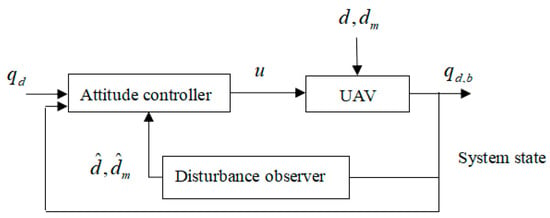
Figure 1.
Attitude control diagram of the quadrotor UAV.
4.2. Nonlinear Disturbance Observer Design
For the mismatched disturbances in Equation (11), inspired by [23], the nonlinear disturbance observer based on a UAV model is shown as follows.
where z1 = [zm1 zm2 zm3]T and z2 = [zp1 zq2 zr3]T are variable vectors, and L is the gain of the nonlinear observer, a third-order positive diagonal matrix.
When considering the matched disturbances, as shown in Equation (2), the nonlinear disturbance observer model is described as follows.
where z3 = [zn1 zn2 zn3]T is an intermediate and variable vector.
Assumption 1.
The input command qd and its second derivative exist and are bounded.
Assumption 2.
The norms of mismatched disturbances dm and matched disturbances d are satisfied as and, whereandare unknown positive numbers.
The observation errors of the nonlinear mismatched disturbance observer are defined as and . The observation error of the nonlinear matched disturbance observer is defined as .
Theorem 2.
The estimation errors of the nonlinear mismatched and matched disturbance observers are convergent.
Proof of Theorem 2.
Taking observer (12) for mismatched disturbances as an example, the corresponding convergence of this nonlinear disturbance observer can be analyzed. Equation (14) can be obtained by substituting Equations (11) and (12) into the derivative of and
Define the error of the observer (12). Equation (15) can be obtained by substituting Equation (14) into the derivative of .
where
By choosing the appropriate parameter L, the eigenvalues of can be located in the left half open plane, so the error system is asymptotic stability, which is convergent. Similarly, the estimation error of observer (13) for matched disturbances converges. □
4.3. Fault Tolerant Controller Design for an Adaptive Sliding Mode and Backstepping Based on a New Fractional-Order Sliding Mode Surface
The error quaternion is defined as qe, as described in Equation (16), and defines the vector eq in Equation (17).
where , according to the backstepping control method, is the virtual control variable to be designed and , .
For the attitude control system of the quadrotor UAV, in order to accelerate the convergence rate, the new sliding mode surface is defined as follows.
where c1, c2, and c3 are the designed parameters, and Dα is a Caputo type fractional-order calculus widely used in recent years, defined as
where , α is the order of the fractional calculus, and it is a fraction. m is the smallest integer not less than α, and f(t) is defined as a continuous integrable function.
However, when the actuator of the UAV is subject to faults, the system Equation (2) can be further described, as shown in Equation (20).
where is the error vector of the actuator u, is the estimate vector of fu, define the actuator error , l1 is a constant parameter, and l1 > 0.
Assumption 3.
Uncertain errors of actuator fu are bounded, and the bound is unknown.
Take the derivative of Equation (19) and substitute in Equation (6); the attitude control law u is designed in Equation (22).
where c4 = diag{c1, c2, c3}, k and h are the designed parameters, and is the estimated value of . Define the gain error of the reaching law , and its adaptive rate is , where the parameter .
For the quadrotor UAV system consisting of Equations (11) and (20), consider the Lyapunov function, V2
The derivative of V2 is
Substitute Equations (21) and (22) and the adaptive rate into Equation (24),
where and converge to 0 in finite time, according to Theorem 2. If parameter h > 0, then , and the attitude control system of UAV is proved to be stable.
5. Simulation Experiments
In order to verify the effectiveness of the new reaching law, the new fractional-order sliding mode surface, and the fault tolerant controller for the UAV attitude control, a series of simulation tests are carried out in this section.
In this paper, the moments of inertia of the quadrotor UAV are , , and . The initial quaternion is chosen, and the expected quaternion is selected. The initial angular velocity is , and the mismatched disturbances dm and the matched disturbance torque d are
which are applied to quadrotor UAV’s attitude control system. The simulation results are shown in Figure 2, Figure 3, Figure 4 and Figure 5.
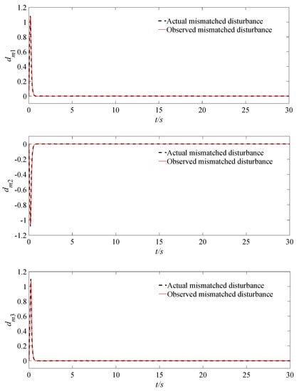
Figure 2.
The responses of actual and observed mismatched disturbances dm.
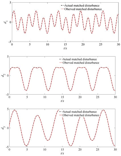
Figure 3.
The responses of actual and observed matched disturbances d.
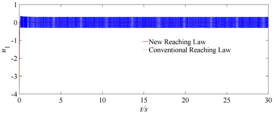
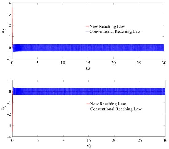
Figure 4.
Responses of the controller outputs ui under the conventional reaching law and the new reaching law proposed in this paper.
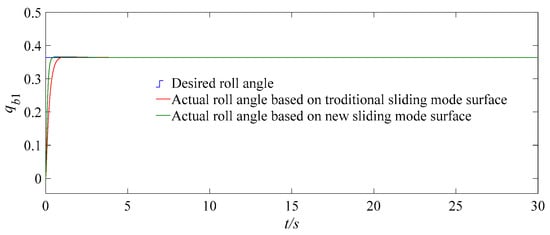
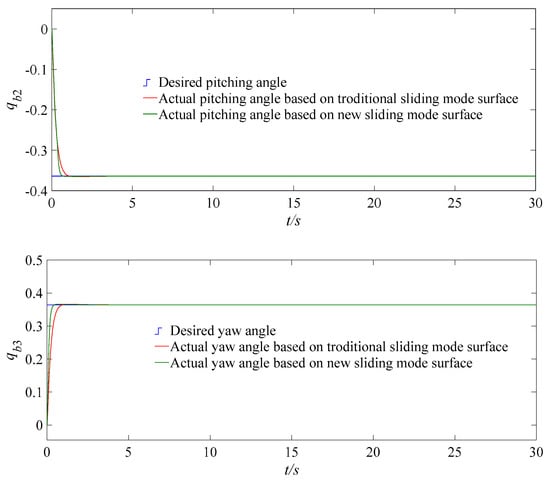
Figure 5.
Tracking responses of UAV attitude angle under two sliding mode surfaces, with mismatched disturbances and actuator failures.
As shown in Figure 2 and Figure 3, the disturbance observer can quickly and accurately track the actual mismatched disturbances dm and d, respectively, after short fluctuations. The estimated errors of the disturbances are also very small, which can suppress the disturbance effects on the control system; therefore, the quadrotor UAV attitude control system is less affected by disturbances.
Under the same conditions, the simulation experiments are conducted for a UAV system by using a new reaching law and a conventional reaching law, as shown in Equations (6) and (5), respectively. The corresponding controller angle response results are shown in Figure 4. It can be seen that the chattering amplitude applied by the new reaching law is significantly reduced compared to that of the conventional reaching law, and the sigmoid function is adopted to effectively suppress the chattering of the controller.
Then traditional and proposed controllers are used for the attitude system of the quadrotor UAV. The traditional control law adopting the traditional backstepping sliding mode surface is shown in Equation (26). The controller using the new sliding mode surface is shown in Equation (21). The two controllers use the same parameters and select the design parameters c1 = 0.4, c2 = 1, c3 =3, l1 = 0.056, k = 1, L = diag{20, 20, 20} and h = 20.
When the faults occur in the actuators, the tracking responses of the UAV attitude angles system, with mismatched disturbances, are shown in Figure 5, which adopt the new reaching law, the adaptive backstepping control, and the fractional-order sliding mode control. Under the same conditions, the simulation experiments are conducted for a UAV system by using the new fractional-order sliding mode control and the traditional backstepping sliding mode control. Figure 5 shows that the speed for tracking the desired command is improved significantly when the new fractional-order sliding mode surface is adopted, the speed of the convergence rate is also improved significantly, and each attitude angle of the quadrotor UAV with mismatched disturbances can reach the expected command with about 0.96 s accurately.
Furthermore, this study also conducts an experiment on the quadrotor aircraft flight simulation software (QDroneGimbalSim) produced by the Quanser Company. The experiment is carried out in a cubic space with a side of 2 m, the vector of the initial position and yaw angle is , and the vector of the desired position and yaw angle is ; the simulation results are shown in Figure 6.
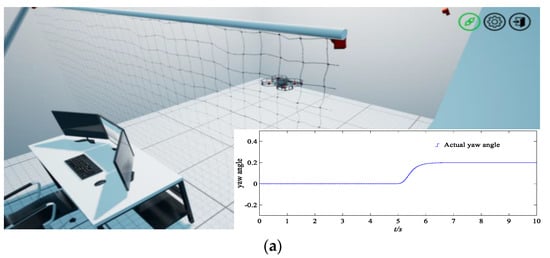
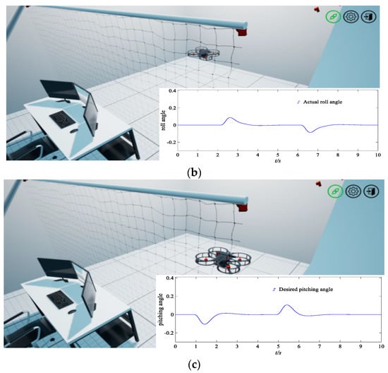
Figure 6.
Flight simulation experiments of a quadrotor UAV and the tracking curves of yaw angle, roll angle, and pitching angle. (a) The initial stage of the quadrotor UAV and tracking responses of an actual yaw angle. (b) The quadrotor UAV in flight, and the tracking responses of an actual roll angle. (c) The final stage approaching the target, and tracking responses of an actual pitching angle.
As shown in Figure 6, the quadrotor UAV can fly stably, the corresponding response speed is fast when the expected command changes, and the test process shows great rapidity and robustness by using the new approach rate and new fractional-order sliding mode surface established in this paper.
6. Conclusions
This paper establishes the attitude control model of a quadrotor UAV when considering mismatched disturbances based on quaternion, proposes a new reaching law based on the sigmoid function, designs a fault tolerant controller which includes sliding mode control and backstepping control methods, and combines the nonlinear disturbance observer method. The main conclusions of this paper can be summarized as follows. (1) Compared to the traditional reaching law, the chattering problem of the UAV attitude controller is significantly reduced using the new reaching law proposed in this paper. (2) The nonlinear disturbance observer designed in this paper can effectively estimate the mismatched disturbances and matched disturbances. (3) The control method based on the new fractional-order sliding mode surface subject to actuator faults can offset the adverse effects of mismatched disturbances for the UAV system, and the quadrotor UAV can stably, accurately and quickly achieve the desired attitude.
Author Contributions
Conceptualization, R.W. and J.L.; methodology, J.L. and H.S.; software, J.L.; validation, R.W. and J.L.; formal analysis, J.L.; investigation, J.L.; resources, R.W. and J.L.; data curation, R.W. and J.L.; writing—original draft preparation, R.W., J.L. and K.Y.; writing—review and editing, R.W., J.L. and K.Y.; visualization, J.L.; supervision, J.L.; project administration, J.L.; funding acquisition, K.Y. All authors have read and agreed to the published version of the manuscript.
Funding
This work was funded by the Key Research and Development Program of Tianjin, China (Grant number, 22YFZCSN00210).
Data Availability Statement
Not applicable.
Acknowledgments
The authors sincerely thank Youmin Zhang from the Department of Mechanical, Industrial, and Aerospace Engineering, Concordia University, Canada, and the Quanser Company for their support and their constructive suggestions regarding the experiments in this work.
Conflicts of Interest
The authors declare no conflict of interest.
References
- Xian, B.; Hao, W. Nonlinear robust fault-tolerant control of the tilt trirotor UAV under rear servo’s stuck fault: Theory and experiments. IEEE Trans. Ind. Inform. 2019, 15, 2158–2166. [Google Scholar] [CrossRef]
- Sun, H.; Yan, J.; Qu, Y.; Ren, J. Sensor fault-tolerant observer applied in UAV anti-skid braking control under control input constraint. J. Syst. Eng. Electron. 2017, 28, 126–136. [Google Scholar] [CrossRef]
- Yu, Z.; Qu, Y.; Zhang, Y. Distributed fault-tolerant cooperative control for multi-UAVs under actuator fault and input saturation. IEEE Trans. Control Syst. Technol. 2019, 27, 2417–2429. [Google Scholar] [CrossRef]
- Jung, D.; Tsiotras, P. Bank-to-turn control for a small UAV using backstepping and parameter adaptation. IFAC Proc. Vol. 2008, 41, 4406. [Google Scholar] [CrossRef]
- Zong, Q.; Zhang, R.; Dong, Q.; Zhang, C. Adaptive sliding mode control for fixed ving unmanned aerial vehicle. J. Harbin Inst. Technol. 2018, 50, 147–155. [Google Scholar]
- Liu, J.; Sun, F. Research and development on theory and algorithms of sliding mode control. Control Theory Appl. 2007, 3, 407–418. [Google Scholar]
- Cai, C.; Guo, L.; Liu, J. Fuzzy sliding mode predictive control of air flow rate for a high-speed high-temperature heat-airflow test system. Int. J. Aeronaut. Space Sci. 2020, 15, 708–714. [Google Scholar] [CrossRef]
- Zhao, F.; Luo, W.; Gao, F.; Yu, J. An improved sliding sode sontrol for PMSM considering sliding mode chattering and disturbance compensation. J. Xi Jiaotong Univ. 2020, 54, 28–35. [Google Scholar]
- Zheng, C.; Zhang, J.; Chen, R. Discrete-time sliding mode control based on improved disturbance compensation reaching law. Control Decis. 2019, 34, 880–884. [Google Scholar]
- Sami, I.; Ullah, S.; Khan, L.; Al-Durra, A.; Ro, J.S. Integer and fractional-order sliding mode control schemes in wind energy conversion systems: Comprehensive review, comparison, and technical insight. Fractal Fract. 2022, 6, 447. [Google Scholar] [CrossRef]
- Mao, J.; Li, Q.; Zhu, H. A continuous nonsingular fast terminal sliding mode control method. Control Decis. 2016, 31, 1873–1878. [Google Scholar]
- Junejo, A.K.; Xu, W.; Mu, C.; Ismail, M.M.; Liu, Y. Adaptive speed control of PMSM drive system based a new sliding-mode reaching law. IEEE Trans. Power Electron. 2020, 35, 12110–12121. [Google Scholar] [CrossRef]
- Chen, X.; Li, Y.; Ma, H.; Tang, H.; Xie, Y. A novel variable exponential discrete time sliding mode reaching law. IEEE Trans. Circuits Syst. II Express Briefs 2021, 68, 2518–2522. [Google Scholar] [CrossRef]
- Chen, X.; Lin, H.; Ma, D. Sliding mode extremum-seeking control for all-electric active braking system in unmanned aerial vehicle. Control Theory Appl. 2015, 32, 1439–1448. [Google Scholar]
- Rui, X.; Yin, W.; Dong, Y. Fractional-order sliding mode control for hybrid drive wind power generationsystem with disturbances in the grid. Wind Energy 2019, 22, 49. [Google Scholar] [CrossRef]
- Alebi, J.; Ganjefar, S. Fractional order sliding mode controllerdesign for large scale variable speed wind turbine for poweroptimization. Environ. Prog. Sustain. Energy 2018, 37, 2124. [Google Scholar]
- Jia, T.; Li, X.; Zhang, X. Neural network sliding mode control for vehicle inertial stabilized platform. Control Theory Appl. 2020, 38, 13–22. [Google Scholar]
- Farrell, J.A.; Polycarpou, M.; Sharma, M.; Dong, W. Command filtered backstepping. IEEE Trans. Autom. Control 2009, 54, 1391–1395. [Google Scholar] [CrossRef]
- Yang, L.; Zhang, W.; Huang, D.; Che, J. Adaptive fuzzy backstepping control for underactuated quadrotor UAV. J. Northwestern Polytech. Univ. 2015, 3, 495–499. [Google Scholar]
- Feng, J.; Zhang, H.; Zhang, X.; Yang, F. Application of backstepping sliding mode algorithm in quadrotor UAV attitude fault-tolerant control. J. Northeast Agric. Univ. 2022, 53, 55–65. [Google Scholar]
- Chen, F.; Jiang, R.; Zhang, K.; Jiang, B.; Tao, G. Robust backstepping sliding-mode control and observer-based fault estimation for a quadrotor UAV. IEEE Trans. Ind. Electron. 2016, 63, 5044–5056. [Google Scholar] [CrossRef]
- Qiao, J.; Dai, Y.; Liu, J. Sliding backstepping control for helicopters with nonlinear disturbance observer. J. Beijing Inst. Technol. 2009, 29, 224–228. [Google Scholar]
- Fang, X.; Wu, A.; Dong, N. Robust trajectory tracking control for unmanned helicopter with mismatched disturbances. Control Theory Appl. 2015, 32, 1325–1334. [Google Scholar]
- Yu, C.; Jiang, J.; Zhen, Z.; Bhatia, A.; Wang, S. Adaptive backstepping control for air-breathing hypersonic vehicle subject to mismatched uncertainties. Aerosp. Sci. Technol. 2020, 107, 106244. [Google Scholar] [CrossRef]
- Yang, J.; Li, S.; Yu, X. Sliding-mode control for systems with mismatched uncertainties via a disturbance observer. IEEE Trans. Ind. Electron. 2013, 60, 160–169. [Google Scholar] [CrossRef]
- Yang, J.; Su, J.; Li, S.; Yu, X. High-order mismatched disturbance compensation for motion control systems via a continuous dynamic sliding-mode approach. IEEE Trans. Ind. Inform. 2014, 10, 604–614. [Google Scholar] [CrossRef]
- Xiao, S. The method of quaternion and its application. Adv. Mech. 1993, 02, 249–260. [Google Scholar]
- Abaunza, H.; Castillo, P. Quadrotor aggressive deployment, using a quaternion-based spherical chattering-free sliding-mode controller. IEEE Trans. Aerosp. Electron. Syst. 2020, 56, 1979–1991. [Google Scholar] [CrossRef]
Disclaimer/Publisher’s Note: The statements, opinions and data contained in all publications are solely those of the individual author(s) and contributor(s) and not of MDPI and/or the editor(s). MDPI and/or the editor(s) disclaim responsibility for any injury to people or property resulting from any ideas, methods, instructions or products referred to in the content. |
© 2023 by the authors. Licensee MDPI, Basel, Switzerland. This article is an open access article distributed under the terms and conditions of the Creative Commons Attribution (CC BY) license (https://creativecommons.org/licenses/by/4.0/).