Article

A Nonlinear Fractional BEM Model for Magneto-Thermo-Visco-Elastic Ultrasound Waves in Temperature-Dependent FGA Rotating Granular Plates

by
Mohamed Abdelsabour Fahmy
Department of Basic Sciences, Adham University College, Umm Al-Qura University, Makkah 28653, Saudi Arabia
Fractal Fract. 2023, 7(3), 214; https://doi.org/10.3390/fractalfract7030214
Submission received: 30 January 2023 / Revised: 14 February 2023 / Accepted: 23 February 2023 / Published: 24 February 2023
(This article belongs to the Special Issue Nonlinear Functional Analysis and Applications)

Abstract

:
The primary goal of this study is to create a nonlinear fractional boundary element method (BEM) model for magneto-thermo-visco-elastic ultrasound wave problems in temperature-dependent functionally graded anisotropic (FGA) rotating granular plates in a constant primary magnetic field. Classical analytical methods are frequently insufficient to solve the governing equation system of such problems due to nonlinearity, fractional order heat conduction, and strong anisotropy of mechanical properties. To address this challenge, a BEM-based coupling scheme that is both reliable and efficient was proposed, with the Cartesian transformation method (CTM) used to compute domain integrals and the generalized modified shift-splitting (GMSS) method was used to solve the BEM-derived linear systems. The calculation results are graphed to show the effects of temperature dependence, anisotropy, graded parameter, and fractional parameter on nonlinear thermal stress in the investigated plates. The numerical results validate the consistency and effectiveness of the developed modeling methodology.

1. Introduction

Functionally graded materials (FGMs) are new composite materials with material properties that vary spatially continuously. This variation in material properties is achieved through gradient variation in the relative volume fraction of the material constituents within the solid. The fundamental benefit of FGMs over laminated composite materials is the seamless and smooth change in material properties over the length or depth of the structure, in contrast, the material properties of the laminated composite are discontinuous, resulting in a sharp shift in the mechanical properties between layers, which can cause delamination and cracks [1]. Functionally graded material (FGM) was first discussed in Japan in 1984, during a space aircraft project in which the materials used had to be able to withstand high-temperature gradients. FGMs have a wide range of engineering applications, including heat shields for spaceships, rocking-motor casings, critical engine parts, and the pharmaceutical industry [2]. Majak et al. [3] focused on the approximation of grading functions of FGM. The latter higher order function approximation technique is extended for modeling grading functions of FGM using the higher order Haar wavelet method (HOHWM). As a result, the generalized algorithm can be used to solve governing equations for various grading functions (exponential, power law, four-parameter functions, etc.). The second order derivatives of the grading functions are expanded into Haar wavelets, providing fourth order convergence with respect to mesh. Many researchers have recently developed different dual phase lag thermo-elastic models [4,5,6,7,8].
The theory [9] and applications [10,11,12] of calculus of any noninteger order are dealt with in fractional order calculus (FOC). Robotics, applied mathematics, food engineering, polymers, economics, finance, econophysics, mathematical biology, bioheat models, physics, chemistry, biomedicine, optimization, chaos theory, electro-hydraulic systems, quantum mechanics, continuum mechanics, fluid mechanics, signal and image processing, nanotechnology, and other applications have made FOC very popular.
For plate problems, the boundary element method (BEM) has emerged as a viable numerical solution. Wang and Huang [13] were the first to model orthotropic thick plates using the BEM. There has been a lot of interest in meshless approaches to continuum mechanics problems [14]. For such plates, meshless approaches with continuous stress approximation are more practical [15]. Krysl and Belytschko [16] used the element-free Galerkin approach to solve plate problems for the first time. Although their results demonstrated excellent convergence, their formulation is not applicable to shear deformable plate problems. Fahmy [17] investigated three-temperature distributions in carbon nanotube fiber-reinforced plates with inclusions using the BEM.
In general, finding an analytical solution to a problem is extremely difficult. As a result, several engineering papers devoted to numerical methods have investigated such problems in various thermo-elasticity topics, such as thermo-elastic metal and alloy discs [18], high-energy dissipation visco-elastic dampers [19], nonlocal thermo-elasticity [20], and micropolar magneto-thermo-visco-elasticity [21]. Several papers, however, have used the boundary element method in general to solve problems such as temperature-dependent composites [22], smart semiconductors [23], and circular cylindrical shells [24]. The meshless local Petrov–Galerkin (MLPG) method [25] has also been successfully applied to plate problems [26,27,28].
In the present paper, a new nonlinear fractional BEM-based coupling strategy is proposed employing the generalized modified shift-splitting (GMSS) method and the Cartesian transformation method (CTM) to solve magneto-thermo-visco-elastic ultrasound wave problems in temperature-dependent FGA rotating granular plates. The calculated results are graphed to demonstrate the effects of temperature dependence, anisotropy, graded parameter, and fractional parameter on nonlinear thermal stress in the investigated plates. The numerical results demonstrate the proposed modeling methodology’s dependability and efficiency.

2. Formulation of the Problem

The governing equations of magneto-thermo-visco-elastic ultrasonic wave propagation problems for temperature-dependent functionally graded anisotropic (FGA) rotating granular structures can be expressed as in Fahmy [29] as follows:
σ p j , j + τ p j , j + Γ p j ρ ω 2 x p = ρ ( x + 1 ) m u ¨ p
σ p j = ( x + 1 ) m [ C p j k l u k , l β p j T ( x , y , τ ) ]
τ p j = μ ( x + 1 ) m ( h ˜ p H j + h ˜ j H p δ j p ( h ˜ k H k ) ) ,           h p = ( × ( u × H ) ) p
Γ p j = ρ ( x + 1 ) m g u k x p
The fractional temperature-dependent heat conduction equation can be written as
D τ a T ( x , τ ) = ξ [ λ ( T ) T ( x ,   τ ) ] + ξ Q ( x ,   T ,   τ ) ,   ξ = 1 ρ ( T ) c ( T )
where
Q ( x ,   T ,   τ ) = Q ¯ ( x ,   T ,   τ ) + 1 R x 0 e ( x a x 0 ) J ( τ ) ,   J ( t ) = J 0   τ τ 1 2 e τ τ 1 ,   a = 1 ,   2 ,   3
For the present problem, it is assumed that the initial/boundary conditions are expressed as
u k ( x , 0 ) = u ˙ k ( x , 0 ) = 0         for   x R   C
u k ( x , τ ) = Ψ k ( x , τ )       for   x C 3
t k ( x , τ ) = δ k ( x , τ )       for   x C 4 ,             τ > 0 ,           C = C 3   C 4 ,   C 3   C 4 =
T ( x ) = f ( x )       for   x R   C
T ( x , τ ) = P ( x , τ )       for   x C 1 ,     τ > 0
q ( x , τ ) = h ¯ ( x , τ )       for   x C 2 ,                     τ > 0 ,         C = C 1   C 2 ,   C 1   C 2 =
A comma followed by a subscript denotes partial differentiation with respect to the corresponding coordinates, while a superposed dot denotes differentiation with respect to time.
Based on Caputo’s scheme, the following formula can be written [30,31]:
D τ a T f + 1 + D τ a T f J = 0 k W a , J ( T f + 1 J ( x ) T f J ( x ) )
where
W a , 0 = ( Δ τ ) a Γ ( 2 a )     and   W a , J = W a , 0 ( ( J + 1 ) 1 a ( J 1 ) 1 a )
By applying Equations (5) and (13), the following formula can be made:
W a , 0 T f + 1 ( x ) λ ( x ,   T ) T , i i f + 1 ( x ) λ , i ( x ,   T ) T , i f + 1 ( x ) = W a , 0 T f ( x ) λ ( x ) T , i i f   ( x ) λ , i ( x ,   T ) T , j f   ( x ) J = 1 f W a , J ( T f + 1 J ( x ) T f J ( x ) ) + h m f + 1 ( x ,   T ,   τ )           + h m f ( x ,   T ,   τ )

3. BEM Solution of Temperature-Dependent Heat Conduction Equation

Based on the implementation of the following Kirchhoff conversion [32]:
Θ = T 0 T λ ( T ¯ ) λ 0 d T ¯
Equation (5) can be written as
2 Θ ( x , τ ) + 1 λ 0 h ( x , Θ ,   τ ) = ρ ( Θ )   c ( Θ ) λ ( Θ ) Θ ( x , τ ) τ
The right-hand side of (17) can be deconstructed as follows:
2 Θ ( x , τ ) + 1 λ 0 h ( x , Θ , τ ) = ρ 0   c 0 λ 0 Θ ( x , τ ) τ + N l ( x , Θ ,   Θ ˙ )
where
N l ( x , Θ ,   Θ ˙ ) = [ ρ ( Θ )   c ( Θ ) λ ( Θ ) ρ 0   c 0 λ 0 ]   Θ ˙
Equation (18) can be written as
2 Θ ( x , τ ) + 1 λ 0 h N l ( x , Θ ,   Θ ˙ ,   τ ) = ρ 0   c 0 λ 0 Θ ( x , τ ) τ
In which
h N l ( x , Θ ,   Θ ˙ ,   τ ) = h ( x , Θ ,   τ ) + [ ρ 0   c 0 λ 0 λ ( Θ ) ρ ( Θ )   c ( Θ ) ]   Θ ˙
The integral equation corresponding to (20) can be expressed using the fundamental solution of (15) as [33]
C ( P ) Θ ( P , τ ¯ n + 1 ) + a 0 Γ τ ¯ n τ ¯ n + 1 Θ ( Q ,   τ ) q ( P , τ ¯ n + 1 ; Q , τ ) d τ   d Γ = a 0 Γ τ ¯ n τ ¯ n + 1 q ( Q ,   τ ) Θ ( P , τ ¯ n + 1 ; Q , τ ) d τ   d Γ + a 0 λ 0 Ω τ ¯ n τ ¯ n + 1 h N l ( Q ,   Θ ,   Θ ˙ ,   τ ) Θ ( P , τ ¯ n + 1 ; Q , τ ) d τ   d Ω + Ω Θ ( Q ,   τ ¯ n ) Θ ( P , τ ¯ n + 1 ; Q , τ ) d Ω ,             a 0 = λ 0 ρ 0 c 0
The fundamental solution and its derivative can be expressed as
Θ ( P , τ ¯ n + 1 ; Q , τ ) = 1 4 π a 0 ( τ ¯ τ ) e x p [ r 2 4 a 0 ( τ ¯ τ ) ] H ( τ ¯ τ )
q ( P , τ ¯ ; Q , τ ) = n Θ ( P , τ ¯ ; Q , τ ) = r 8 π a 0 2 ( τ ¯ τ ) 2 e x p [ r 2 4 a 0 ( τ ¯ τ ) ] H ( τ ¯ τ ) r n
The time integrals for (23) and (24), respectively, can be expressed as
t n t n + 1 Θ ( P , τ ¯ n + 1 ; Q , τ ) d τ = 1 4 π a 0 Ei ( r 2 4 a 0 Δ τ ¯ )
t n t n + 1 q ( P , τ ¯ n + 1 ; Q , τ ) d τ = 1 2 π a 0 r exp ( r 2 4 a 0 Δ τ ¯ ) r n
In which
Ei ( α ) = α exp ( x ) x d x
Consider the following domain integral in Equation (22):
I N l = a 0 λ 0 Ω τ ¯ n τ ¯ n + 1 h N l ( Q ,   Θ ,   Θ ˙ ,   τ ) Θ ( P , τ ¯ n + 1 ; Q , τ ) d τ   d Ω
which can be stated as
I N l = a 0 λ 0 Ω τ ¯ n τ ¯ n + 1 { h ( Q ,   Θ ,   τ ) + [ ρ 0 c 0 λ 0 λ ( Θ ) ρ ( Θ )   c ( Θ ) ]   Θ ˙ } Θ ( P , τ ¯ n + 1 ; Q , τ ) d τ   d Ω
Thus, the following equation can be written:
I N l = 1 4 π λ 0 Ω h N l ( Q ,   Θ n + ( 1 / 2 ) ,     Θ ˙ n + ( 1 / 2 ) ,   τ ¯ n + ( 1 / 2 ) ) Ei ( r 2 4 a 0 Δ τ ¯ ) d Ω
where
h N l ( Q ,   Θ n + ( 1 / 2 ) ,   τ ¯ n + ( 1 / 2 ) ) = h ( Q ,   Θ n + ( 1 / 2 ) ,   τ ¯ n + ( 1 / 2 ) ) + [ ρ 0 c 0 λ 0 λ ( Θ n + ( 1 / 2 ) ) ρ ( Θ n + ( 1 / 2 ) ) c ( Θ n + ( 1 / 2 ) ) ]   Θ ˙ n + ( 1 / 2 )
Then,
Θ n + ( 1 / 2 ) = Θ n + Θ n + 1 2 ,   τ ¯ n + ( 1 / 2 ) = τ ¯ n + τ ¯ n + 1 2 ,     Θ ˙ n + ( 1 / 2 ) = Θ n + 1 Θ n Δ τ ¯
By replacing Θ ( P , τ ¯ n + 1 )   with   2 Θ ( P , τ ¯ n + ( 1 / 2 ) ) Θ ( P , τ ¯ n ) in Equation (31), we obtain
2 C ( P ) Θ ( P , τ ¯ n + ( 1 / 2 ) ) 1 2 π Γ Θ ( Q ,   τ ¯ n + ( 1 / 2 ) ) r e x p [ r 2 4 a 0 Δ τ ¯ ] r n   d Γ = 1 4 π Γ q ( Q ,   τ ¯ n + ( 1 / 2 ) )   Ei ( r 2 4 a 0 Δ τ ¯ ) d Γ + 1 4 π λ 0 Ω h N l ( Q ,   Θ n + ( 1 / 2 ) ,     Θ ˙ n + ( 1 / 2 ) ,   τ ¯ n + ( 1 / 2 ) ) Ei ( r 2 4 a 0 Δ τ ¯ ) d Ω + 1 4 π a 0 Δ τ ¯ Ω   Θ ( Q ,   τ ¯ n ) exp ( r 2 4 a 0 Δ τ ¯ ) d Ω + C ( P ) Θ ( P ,   τ ¯ n )
Now, by using CTM [34,35,36,37], the domain integrals in Equation (32) can be calculated as in Appendix A and Appendix B.
The following equations can be used to compute the unknown boundary and internal values:
H Θ Γ = G Q Γ + F + F N l  
Θ Ω = G ^ Q Γ H ^ Θ Γ + F ^ + F ^ N l
As a result, we can express
𝕒 Χ = 𝕓
In which 𝕒 denotes an unknown matrix, and 𝕓 and Δ denote well-known matrices.

4. BEM Solution of Displacement Field

Making use of (2), (3), and (4), we can write (1) as follows:
L p k u k = ρ u ¨ p ( ( D p k + Λ D p 1 k ρ g ) u k + D p T ρ ω 2 x p ) = ρ u ¨ p ρ b p = ρ b p
where L p k = D p j k x j , D p j k = C p j k l x l ,     D p k = μ H 0 2 ( x p + δ p 1 Λ ) x k , D p = β p j ( x j + δ j 1 Λ ) ,   = x p ,   Λ = m x + 1 .
The representation formula of (36) can be expressed as in Fahmy [29] as
u m ( ξ ) = C ( u m p ( x , ξ ) t p ( x ) t m p ( x , ξ ) u p ( x ) ) d C R u m p ( x , ξ ) ρ b p ( x ) d R
Let
ρ b p = ρ u ¨ p ( ( D p k + Λ D p 1 k ρ g ) u k + D p T ρ ω 2 x p ) q = 1 N f p n q α n q = q = 1 N ( L p k u k n q ) α n q
We proceed in the same way as Fahmy [30] to obtain the following representation formula:
u m ( ξ ) = C ( u m p t p t m p u p ) d C + q = 1 N ( u m n q ( ξ ) C ( u m p t p n q t m p u p n q ) d C ) α n q
The approximate values of the unknowable field variables { u ,   t } and solutions { u q ,   t q } can be written as
{ u ,   t } k = 1 N φ k { u ˇ k ,   t ˇ k } = Φ T { u ˇ ,   t ˇ } ,       { u q ,   t q } k = 1 N φ k { u ˇ k q ,   t ˇ k q } = Φ T { u ˇ q ,   t ˇ q }
where u ˇ ,   t ˇ , and Φ are matrices.
Based on these approximations, the representation formula (39) can be expressed as
ζ u ˇ η t ˇ = q = 1 N ( ζ u ˇ q η t ˇ q ) α q ( τ )
By letting
U ˇ = [ u ˇ 1   u ˇ 2   u ˇ N ] ,   ˇ = [ t ˇ 1   t ˇ 2   t ˇ N ] ,   α = [ α 1   α 2   α N ] T
Equation (41) can be expressed as follows
ζ u ˇ ( τ ) η t ˇ ( τ ) = ( ζ U ˇ η ˇ ) α ( τ )
Using the point collocation approach, Equation (38), produces
ρ u ¨ ˇ ( τ ) ρ b ˇ ( τ ) = F α ( τ )
Now, Equation (44) can be expressed as
α ( τ ) = F 1 ( ρ u ¨ ˇ ( τ ) ρ b ˇ ( τ ) )
Substitution of (45) into (43) yields the system
u ¨ ˇ + ζ u ˇ = η t ˇ ( τ ) + ˇ ( τ )
where
= ( η ˇ ζ U ˇ ) F 1 ,     = ρ ,     ˇ ( τ ) = ρ b ˇ ( τ ) .
Now, we suppose the following:
{ u ˇ k ,   t ˇ u } C 3 ,   { u ˇ u ,   t ˇ k } C 4
where k and u are known and unknown parts, respectively.
The system (46) can be written as
[ 11 12 21 22 ] [ u ¨ ˇ k ( τ ) u ¨ ˇ u ( τ )   ] + [ ζ 11 ζ 12 ζ 21 ζ 22 ] [ u ˇ k ( τ ) u ˇ u ( τ ) ] = [ η 11 η 12 η 21 η 22 ] [ t ˇ k ( τ ) t ˇ u ( τ ) ] + [ ˇ 1 ( τ ) ˇ 2 ( τ ) ]
The unknown fluxes t ˇ u ( τ ) can now be derived from (49) as
t ˇ u ( τ ) = ( η 12 ) 1 [ 11 u ¨ ˇ k ( τ ) + 12 u ¨ ˇ u ( τ ) + ζ 11 u ˇ k ( τ ) + ζ 12 u ˇ u ( τ ) η 11 t ˇ k ( τ ) ˇ 1 ( τ ) ]
From Equations (49) and (50), we have
u u ¨ ˇ u ( τ ) + ζ u u ˇ u ( τ ) = Q k ( τ )
In which
Q k ( τ ) = ˇ k ( τ ) + η k t ˇ k ( τ ) k u ¨ ˇ k ( τ ) ζ k u ˇ k ( τ ) ,   ˇ k ( τ ) = 2 ( τ ) η 22 ( η 12 ) 1 1 ( τ ) ,
u = 22 η 22 ( η 12 ) 1 12 ,   ζ u = ζ 22 η 22 ( η 12 ) 1 ζ 12
k = 21 η 22 ( η 12 ) 1 11 ,   ζ k = ζ 21 η 22 ( η 12 ) 1 ζ 11
At time step n + 1 , Equation (51) can be expressed as
u u ¨ ˇ n + 1 u ( τ ) + ζ u u ˇ n + 1 u ( τ ) = Q n + 1 k ( τ )
where
Q n + 1 k ( τ ) = ˇ n + 1 k ( τ ) + η k t ˇ n + 1 k ( τ ) k u ¨ ˇ n + 1 k ( τ ) ζ k u ˇ n + 1 k ( τ )
Now, to reduce the ordinary differential equations system (52) to an algebraic system, Houbolt’s algorithm is implemented using the following implicit backward finite difference scheme:
u ˙ ˇ n + 1 1 6 Δ τ ¯ ( 11 u ˇ n + 1 18 u ˇ n + 9 u ˇ n 1 2 u ˇ n 2 )
u ¨ ˇ n + 1 1 Δ τ ¯ 2 ( 2 u ˇ n + 1 5 u ˇ n + 4 u ˇ n 1 u ˇ n 2 )
Substituting (53) and (54) into (52), we have
ς u u ˇ n + 1 u ( τ ) = n + 1 k ( τ )
where
ς u = 2 u Δ τ ¯ 2 + ζ u ,         n + 1 k = Q n + 1 k + u Δ τ ¯ 2 ( 5 u ˇ n 4 u ˇ n 1 + u ˇ n 2 )
Our method is described by the following algorithm:
(I)
To resolve the system (55), we use successive over-relaxation (SOR), as outlined in Golub and Van Loan [38].
(II)
The values of u ˇ n + 1 u are determined for each time step n + 1 .
(III)
The values u ˇ n + 1 u can then be used to calculate the unknowns u ˙ ˇ n + 1 u and u ¨ ˇ n + 1 u from (53) and (54), respectively.
(IV)
The method given in Bathe [39] is utilized along with the initial conditions for the scenario where n = 0 to calculate u 1 and u 2 .
(V)
The traction vector t n + 1 u is then calculated using (50).
The semi-implicit predictor–corrector coupling algorithm of Breuer et al. [40] that was based on the generalized modified shift-splitting (GMSS) of Huang et al. [41] has been applied to solve the resulting linear Equations (35) and (55) arising from the BEM, where magneto-thermo-visco-elastic coupling is considered instead of fluid–structure interaction coupling of Breuer et al. [40].

5. Numerical Results and Discussion

In the context of temperature-dependent FGA rotating granular plates, the proposed BEM technique can be applied to a wide range of nonlinear fractional BEM models for magneto-thermo-visco-elastic ultrasound wave problems. The BEM discretization was performed with 42 boundary elements and 68 internal points, as shown in Figure 1.
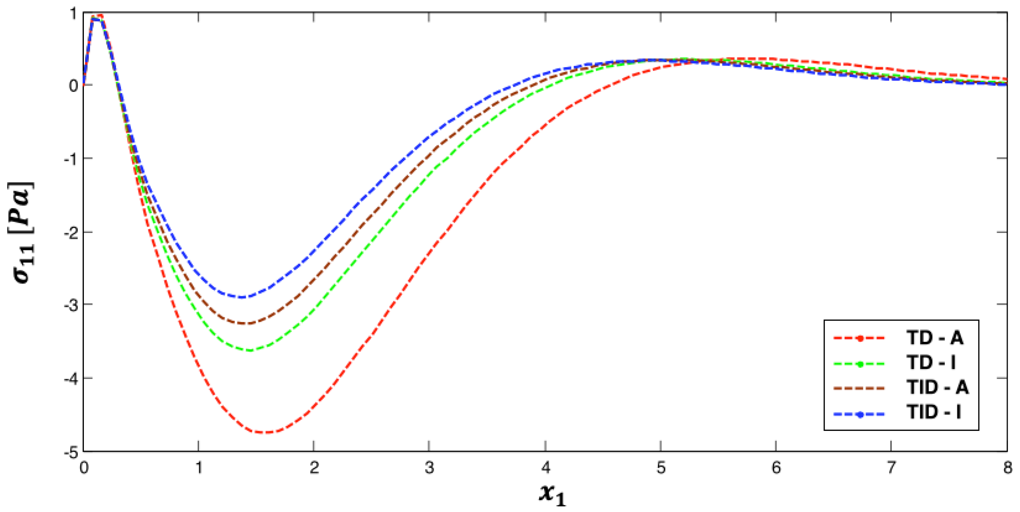
It is noticed from Figure 2 that the temperature-dependent (TD) curve of magneto-thermo-visco-elastic stress σ 11 along the x 1 -axis is under a temperature-independent (TID) curve for isotropic (I) and anisotropic (A) cases. Additionally, it is noticed from this figure that the anisotropic (A) curve is under the isotropic (I) curve for temperature-dependent (TD) and temperature-independent (TID) cases.
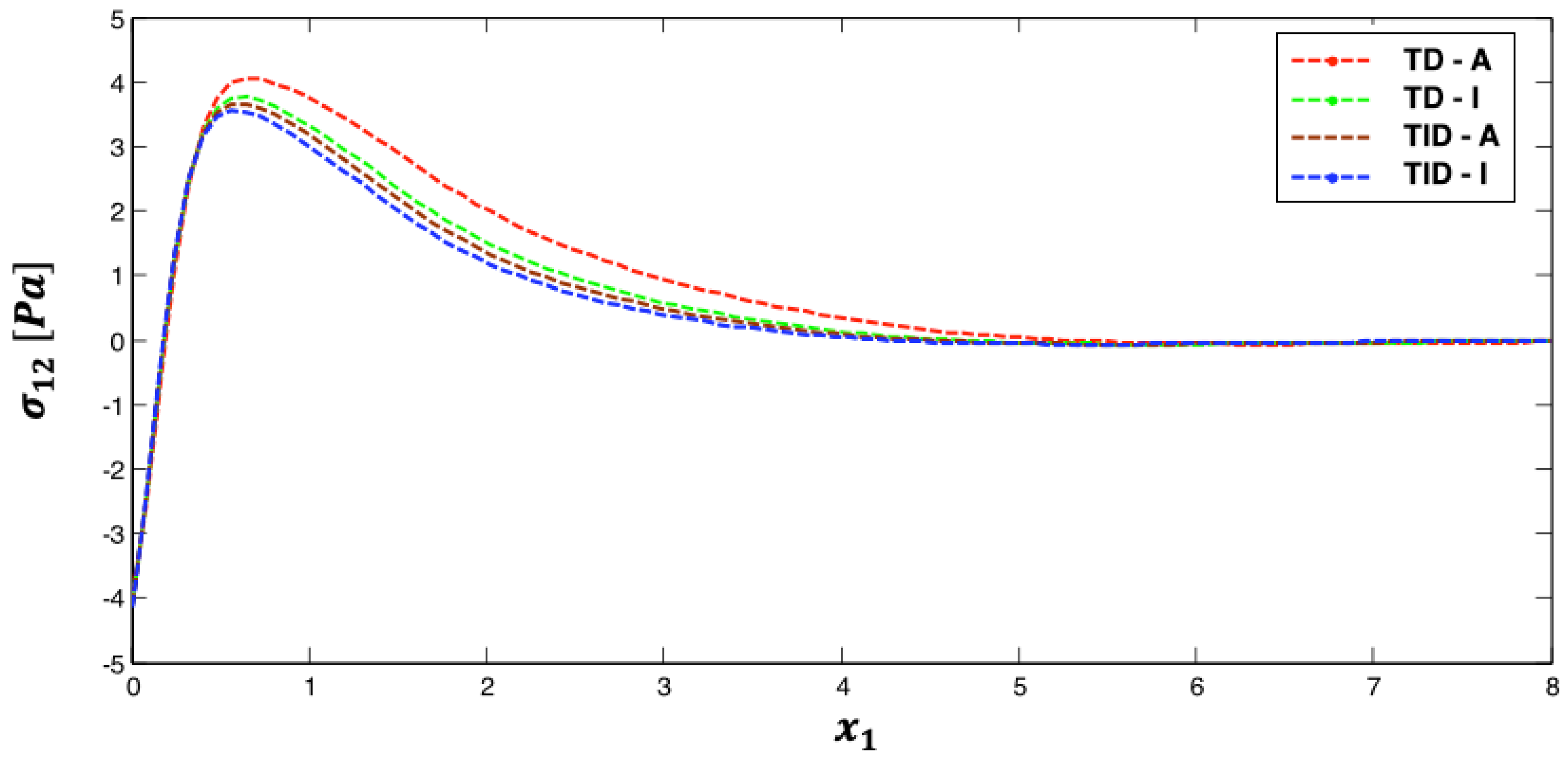
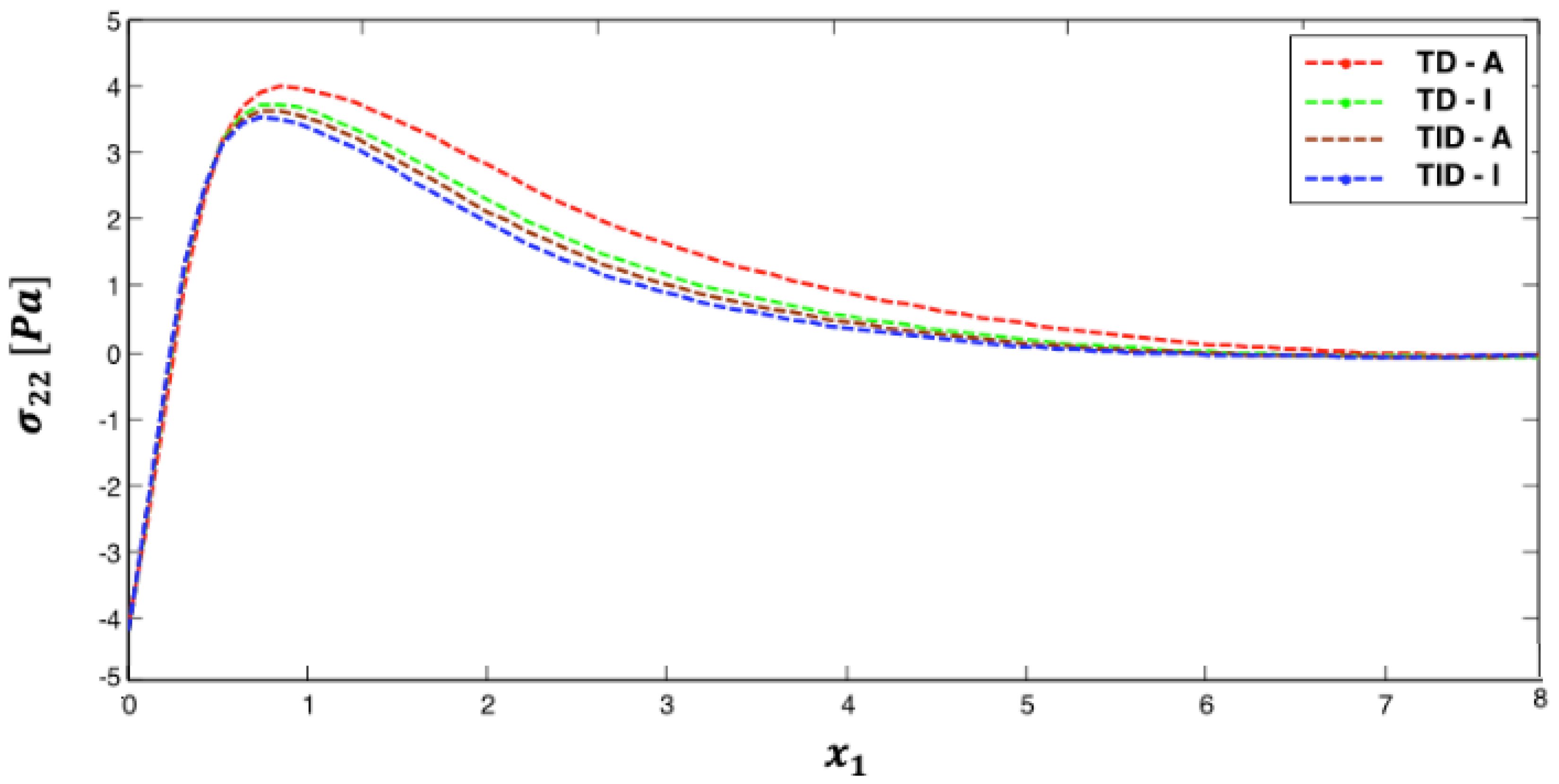
It is noticed from Figure 3 and Figure 4 that the temperature-dependent (TD) curves of magneto-thermo-visco-elastic stress σ 12 and magneto-thermo-visco-elastic stress σ 22 along the x 1 -axis are over temperature-independent (TID) curves for isotropic (I) and anisotropic (A) cases. In addition, it is noticed from these figures that the anisotropic (A) curve is over the isotropic (I) curve for temperature-dependent (TD) and temperature-independent (TID) cases.
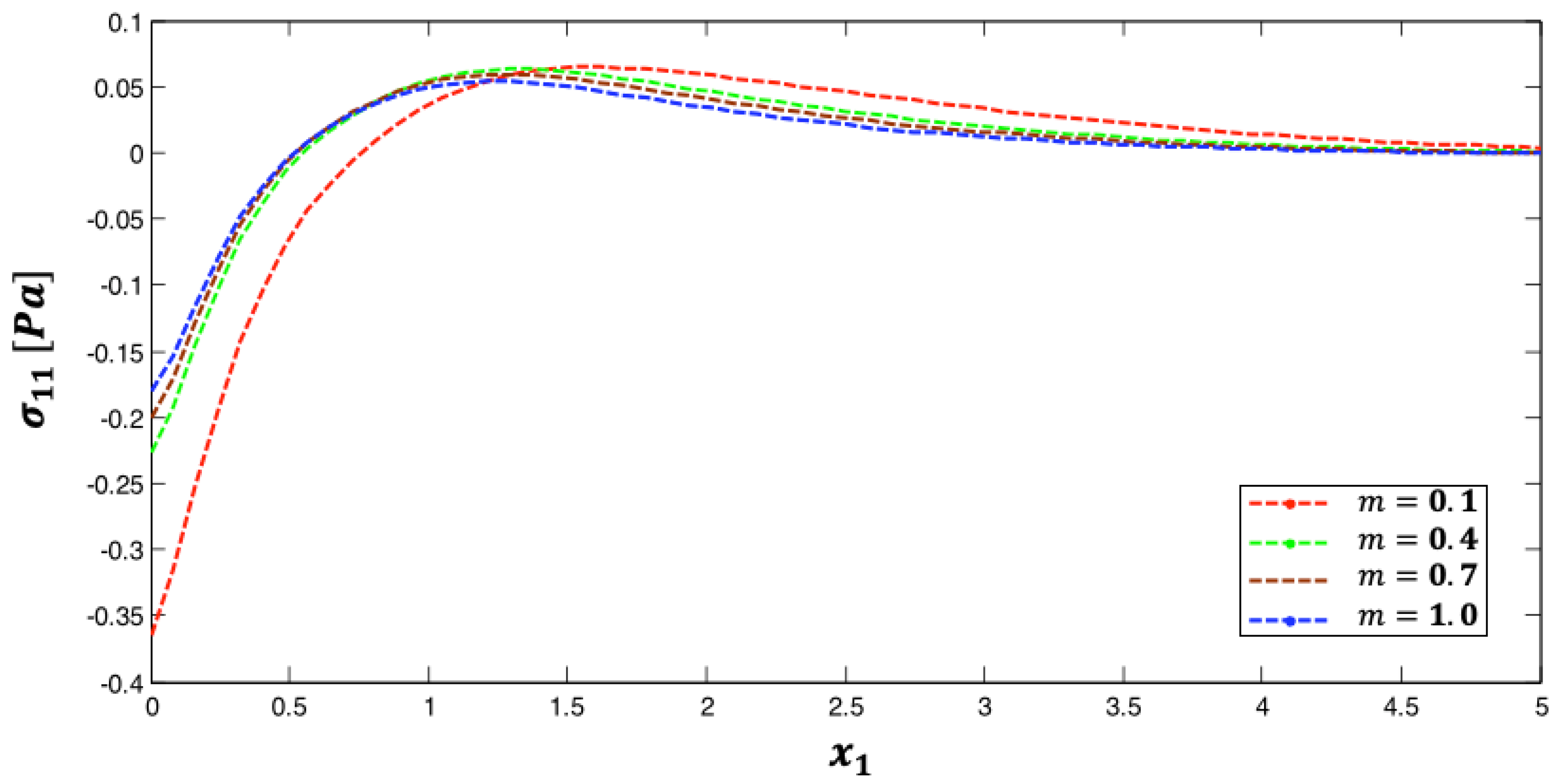
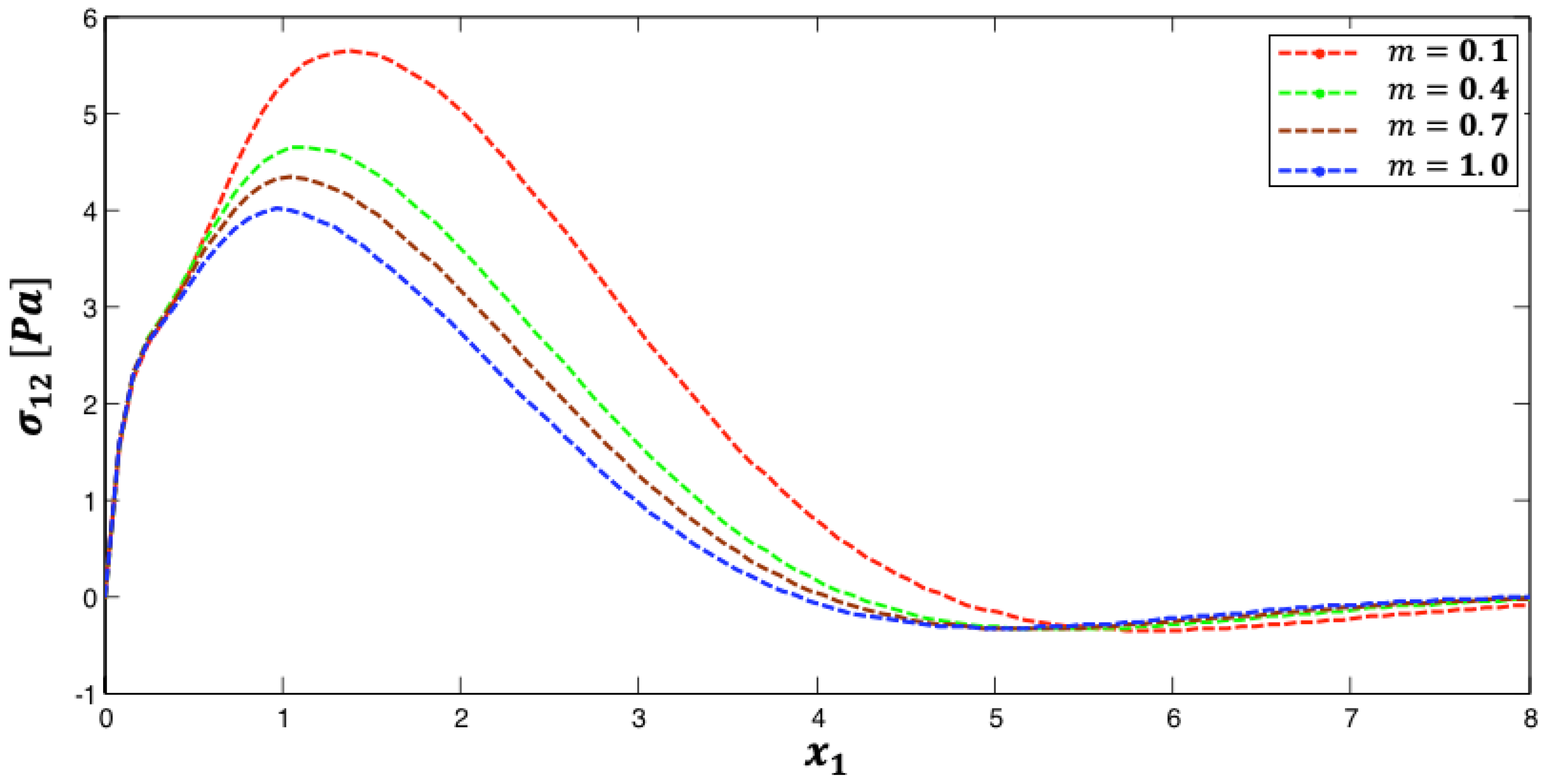
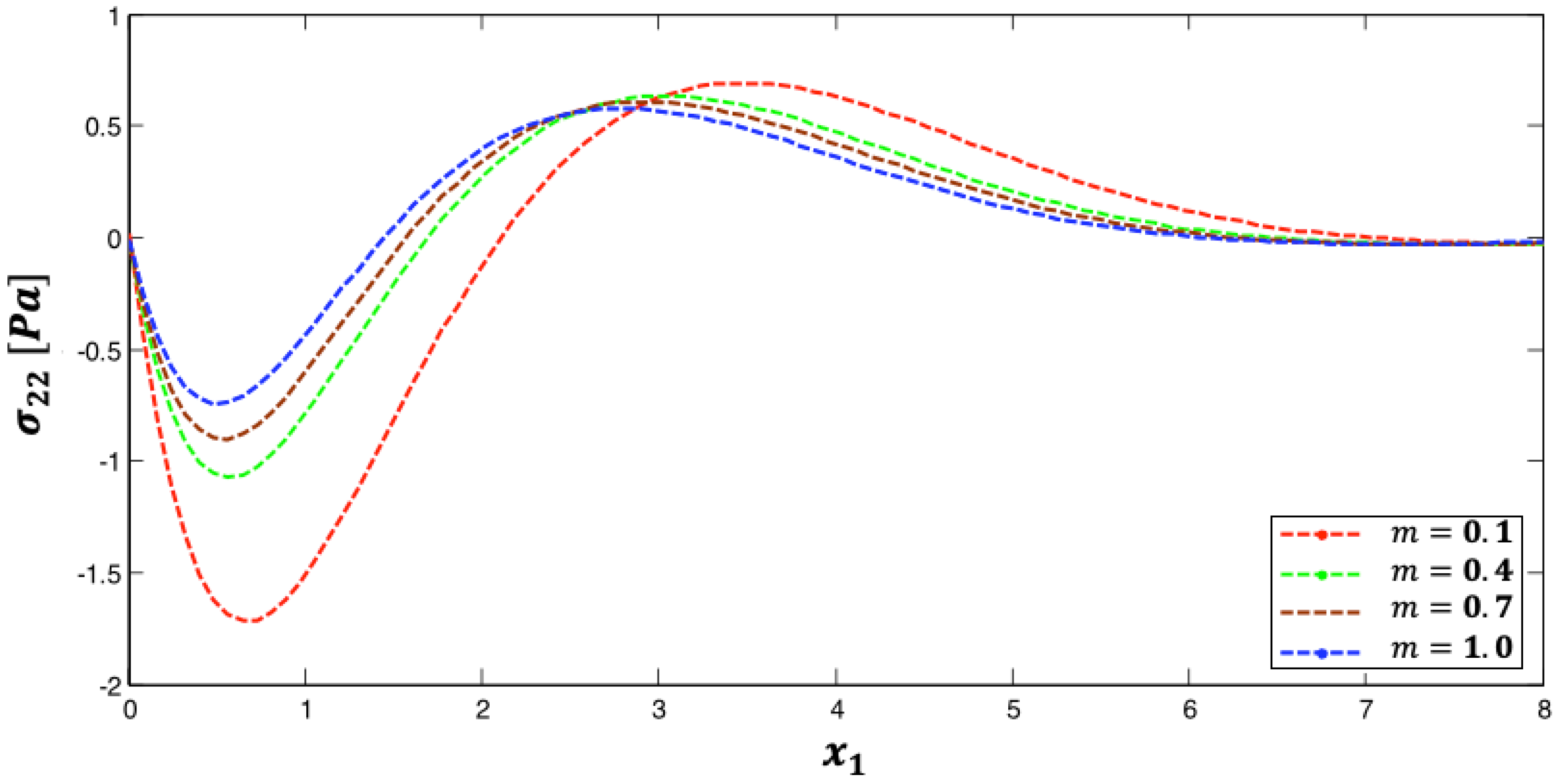
Figure 5, Figure 6 and Figure 7 show the distributions of the magneto-thermo-visco-elastic stresses σ 11 , σ 12 , and σ 22 along the x 1 -axis for different values of the functionally graded parameter ( m = 0.1 ,     0.4 ,     0.7 ,   and   1.0 ).
It is noticed from Figure 5 that the magneto-thermo-visco-elastic stress σ 11 along the x 1 -axis increases with the increase in functionally graded parameter m . Then, it decreases with the increase in the functionally graded parameter m after x 1 = 1.4 .
It is noticed from Figure 6 that the magneto-thermo-visco-elastic stress σ 12 curves along the x 1 -axis at different values of the functionally graded parameter ( m = 0.1 ,   0.4 ,   0.7 ,   and   1.0 ) coincide with each other in 0 x 1 0.5 . Then, they decrease with the increase in functionally graded parameter m until x 1 = 5.7 , then they increase with the increase in functionally graded parameter m .
It is noted from Figure 7 that the magneto-thermo-visco-elastic stress σ 22 along the x 1 -axis increases with the increase in functionally graded parameter m until x 1 = 3 . Then, it decreases with the increase in functionally graded parameter m .
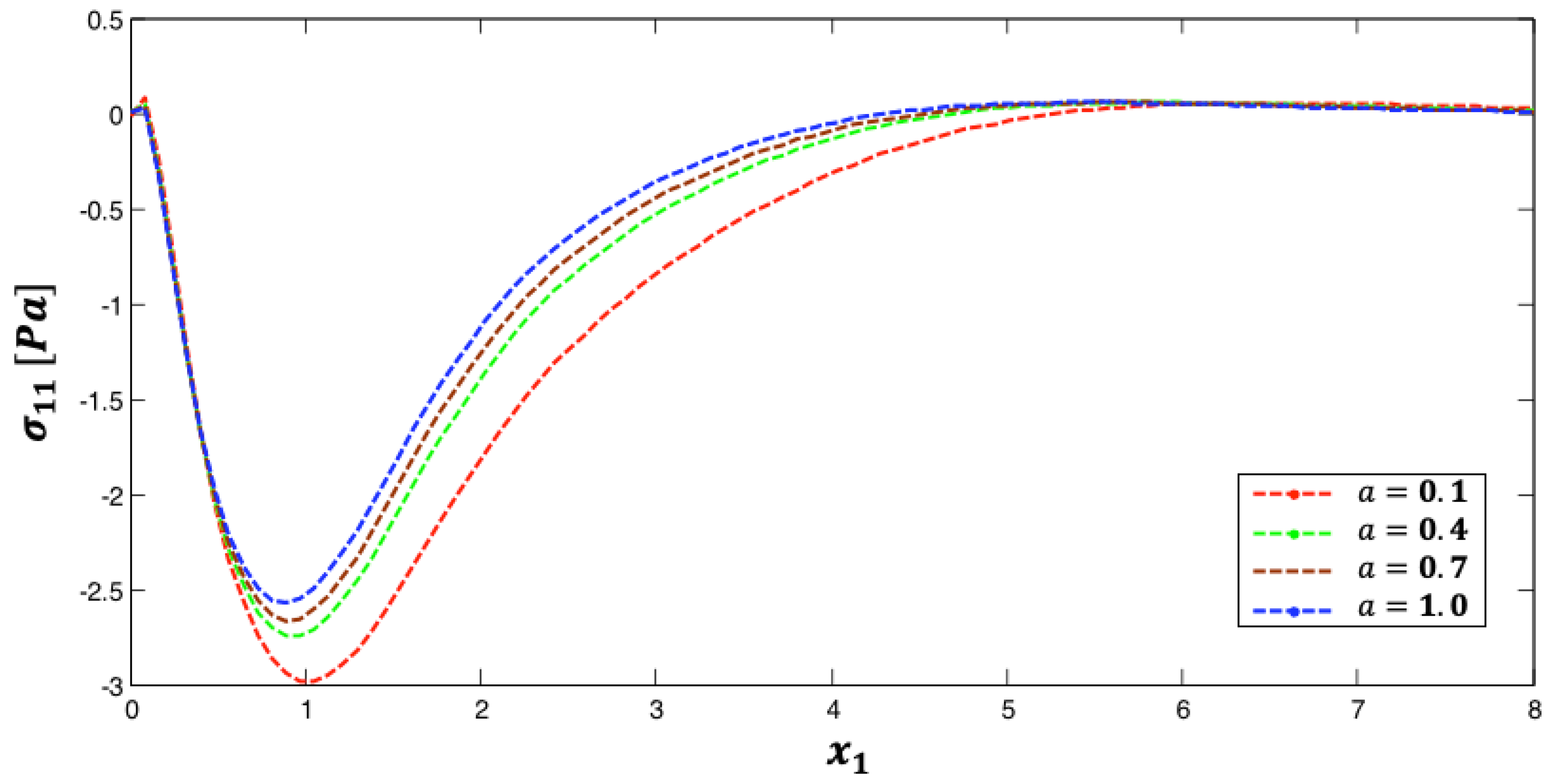
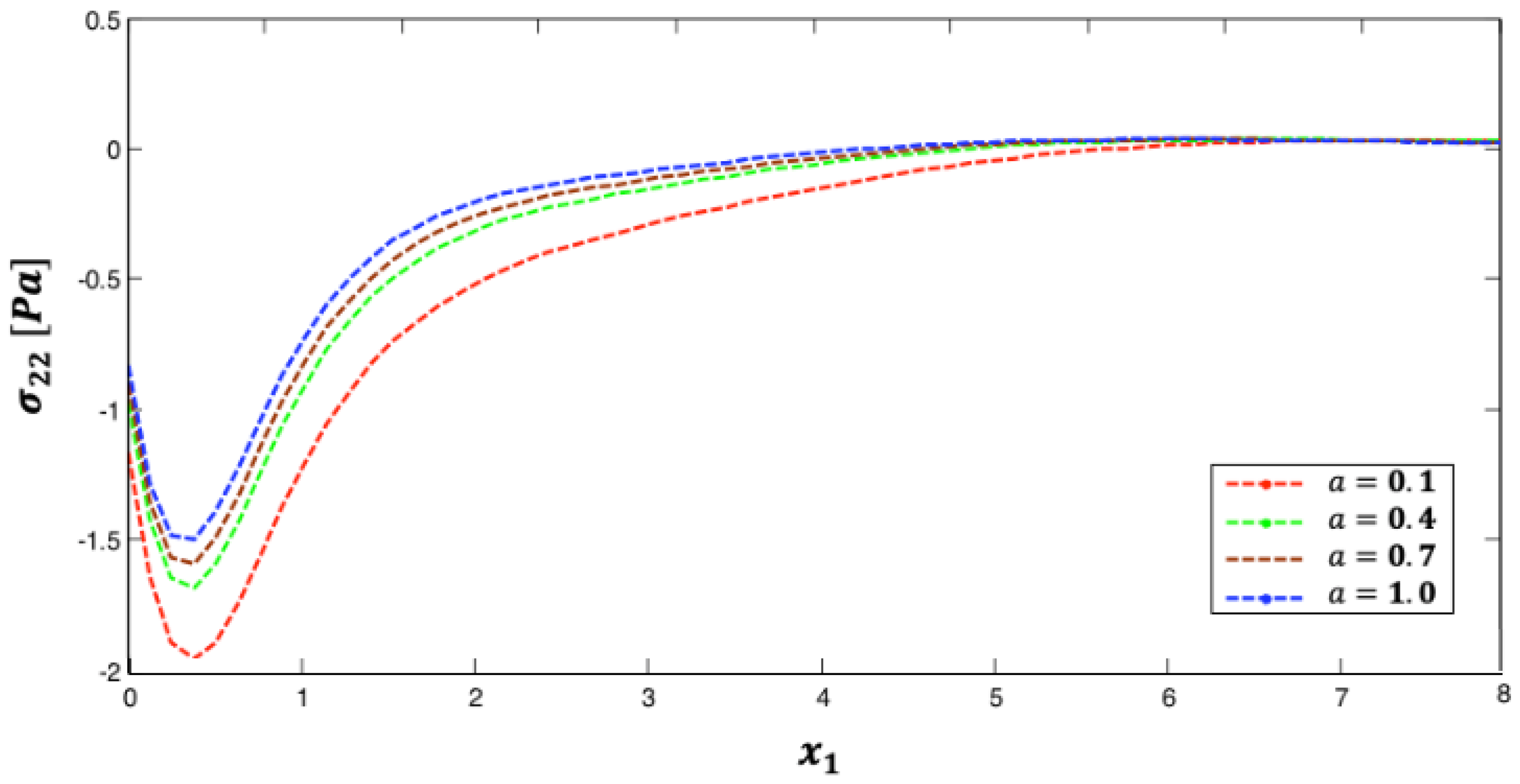
Figure 8, Figure 9 and Figure 10 display the distributions of magneto-thermo-visco-elastic stresses σ 11 , σ 12 , and σ 22 along the x 1 -axis for different values of fractional parameter a = 0.1 ,     0.4 ,     0.7 ,   and   1.0 .
It is noticed from Figure 8 that the magneto-thermo-visco-elastic stress σ 11 curves along the x 1 -axis at different values of the fractional parameter ( a = 0.1 ,     0.4 ,     0.7 ,   and   1.0 ) coincide with each other in 0 x 1 0.5 . Then, they increase with the increase in fractional parameter a until x 1 = 5.85 , then they coincide with each other again.
It is noticed from Figure 9 that the magneto-thermo-visco-elastic stress σ 12 curves along the x 1 -axis at different values of the fractional parameter coincide with each other in 0 x 1 0.5 . Then, they increase with the increase in fractional parameter a until x 1 = 5.5 . Then, they decrease with the increase in fractional parameter a .
It is noticed from Figure 10 that the magneto-thermo-visco-elastic stress σ 22 along the x 1 -axis increases with the increase in fractional parameter a until x 1 = 6.82 , then the magneto-thermo-visco-elastic stress σ 12 curves along the x 1 -axis at considered values of fractional parameter a coincide with each other.
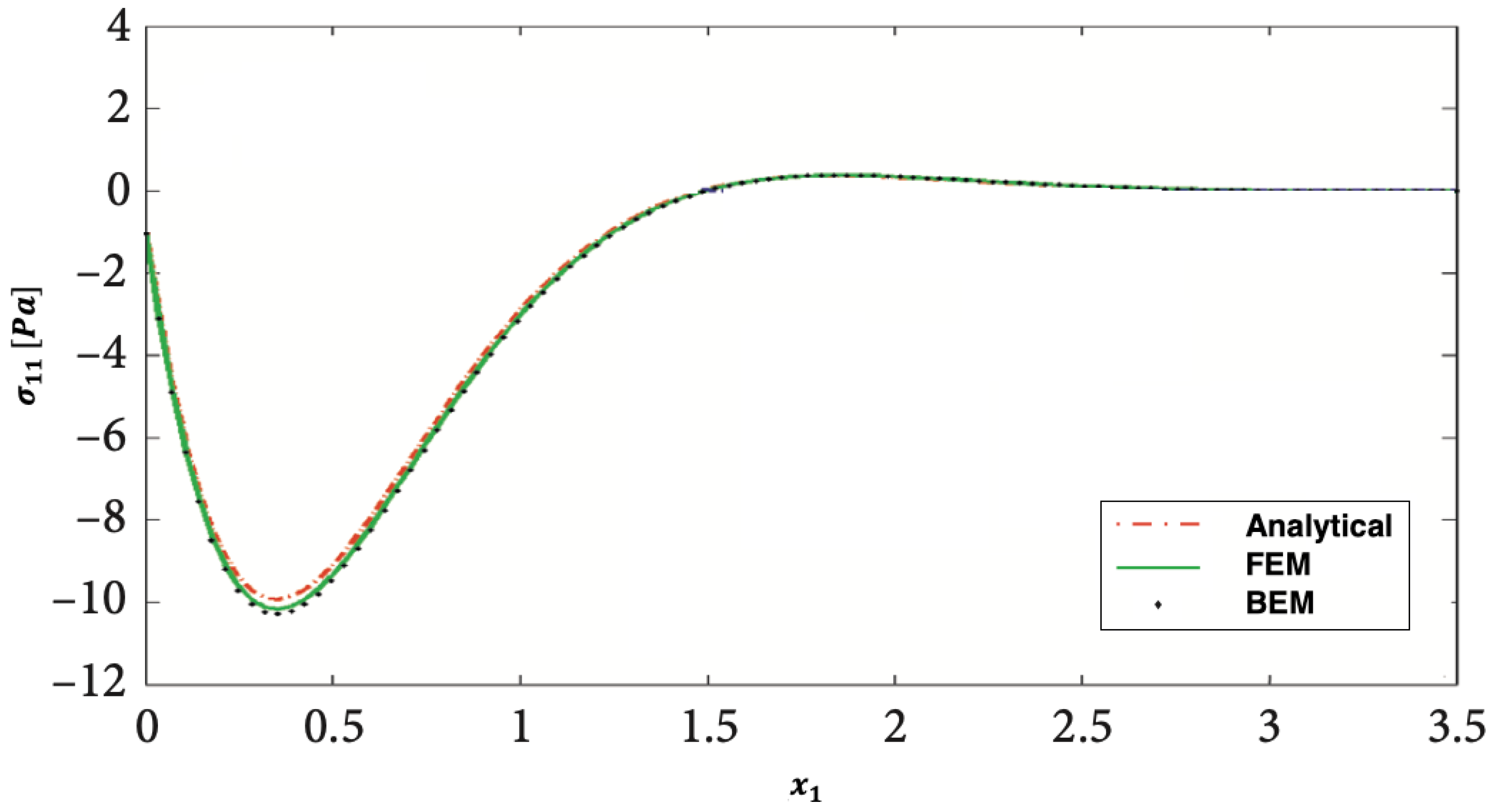
The findings of the proposed technique were not supported by any published findings. However, some literary works might be seen as a part of the research under consideration. Thus, we took a special case of our research into consideration and applied the analytical method of Al-Basyouni et al. [42], the finite element method (FEM) of Pettermann and DeSimone [43], and current BEM to this special case, as shown in Figure 11, Figure 12 and Figure 13 below.
Figure 11, Figure 12 and Figure 13 show the distributions of the magneto-thermo-visco-elastic stresses σ 11 ,   σ 12 ,   and   σ 22 along the x 1 -axis for the analytical method [42], finite element method [43], and current BEM. It is clear from these figures that the BEM is in excellent agreement with the analytical and FEM, thus confirming the validity and accuracy of our proposed technique.
The computation results of the two considered examples were found using Matlab R2018a on a MacBook Pro with 2.9 GHz quad-core Intel Core i9 processor and 16 GB RAM.
The proposed fractional boundary element technique in this study is applicable to a wide range of temperature-dependent FGA rotating granular plate problems. The three effective and potent iterative methods employed to solve the linear systems generated by the proposed technique are communication-avoiding Arnoldi (CA-Arnoldi) [44], Dehdezi and Karimi (D-K) [45], and generalized modified shift-splitting (GMSS) [41] methods.
Table 1 displays the CPU time and number of iterations for the CA-Arnoldi, D-K, and GMSS iterative methods at each discretization level, with the equation values in parentheses. According to Table 1, the GMSS method performs better than the CA-Arnoldi and D-K methods.
Table 2 compares computational resources for modeling temperature-dependent FGA rotating granular plate problems using the lattice Boltzmann method (LBM) of Oshtorjani et al. [46], finite element method (FEM) of Pettermann and DeSimone [43], and the proposed boundary element method (BEM). Table 2 also shows the effectiveness of our proposed boundary element methodology.

6. Conclusions

A summary of this paper is as follows:
  • A numerical BEM scheme is applied to a nonlinear fractional boundary element model for magneto-thermo-visco-elastic ultrasound wave problems in temperature-dependent FGA rotating granular plates.
  • The BEM-based coupling scheme that is both reliable and efficient was proposed, with the Cartesian transformation method (CTM) used to compute domain integrals.
  • The generalized modified shift-splitting (GMSS) method was used to solve the BEM-derived linear systems.
  • Effects of temperature dependence, anisotropy, graded parameter, and fractional parameter on nonlinear thermal stress in the investigated plates are established.
  • The numerical results validate the consistency and effectiveness of the developed modeling methodology.
  • The results presented in this paper can be used in a variety of commercial applications, including the pharmaceutical industry, agriculture, and energy production.

Funding

This research was funded by the Deanship of Scientific Research at Umm Al-Qura University, grant number 22UQU4340548DSR12. The APC was funded by the Deanship of Scientific Research at Umm Al-Qura University.

Data Availability Statement

All data generated or analyzed during this study are included in this published article.

Acknowledgments

The author would like to thank the Deanship of Scientific Research at Umm Al-Qura University for supporting this work, grant code 22UQU4340548DSR12.

Conflicts of Interest

The author declares no conflict of interest.

Nomenclature

β p j Stress–temperature coefficients
Γ p j Gravity field tensor
μ Magnetic permeability
Visco-elastic material constant
ρ Density
σ p j Mechanical stress tensor
τ p j Electro-magnetic stress tensor
τ Time
τ 0 & τ 2 Relaxation times
τ 1 Laser pulse time characteristic
ω Uniform angular velocity
c Specific heat of the plate
C p j k l Constant elastic moduli
g Earth gravity
h ˜ Perturbed magnetic field
J ( τ ) Non-Gaussian temporal profile
J 0 Total energy intensity
k p j Thermal conductivity coefficients
m Graded parameter
R Irradiated surface absorptivity
t k = σ k j n j Tractions
T Temperature
u k Displacement

Appendix A

Using the CTM [34,35], we can calculate the domain integrals with irregularly spaced kernels by considering the following integral.
I = Ω p ( x ) d Ω = Ω p ( x 1 ,   x 2 ) d Ω
By using the theorem of Green as follows:
Ω u ( x 1 ,   x 2 ) x 1 d Ω = Γ u ( x 1 ,   x 2 ) d x 2
we can write
I = Γ P 1 ( x 1 ,   x 2 ) d x 2
where
P 1 ( x 1 ,   x 2 ) = Γ p ( x 1 ,   x 2 ) d x 1
The integral in (A4) can be calculated numerically to produce
P 1 ( x 1 ,   x 2 ) = α x 1 p ( x 1 ,   x 2 ) d x 1
According to the analysis of Khosravifard and Hematiyan [36], the domain integral (A1) can be expressed as follows.
I = Γ ( α x 1 p ( x 1 ,   x 2 ) d x 1 ) d x 2 ,   α = x 1 m i n + x 1 m a x 2
By applying the composite Gaussian quadrature method to (A1), we obtain
I = k = 1 K Γ k α x 1 p ( x 1 ,   x 2 ) d x 1 d x 2
Which may be expressed as
I = k = 1 K J k i = 1 N w i l = 1 L J l j = 1 J w j p ( x 1 ( η j ) ,   x 2 ( η i ) )
Based on the radial point interpolation method (RPIM) of Liu and Gu [37], we obtain
p ( x 1 ,   x 2 ) = i = 1 M ϕ i ( x 1 ,   x 2 ) p i = Φ T Ρ ,     M = M + M
The foundation established by Liu and Gu [37] allows us to express p ( x 1 ,   x 2 ) as follows:
p ( x ) = i = 1 n α i ψ i ( x ) + j = 1 m ¯ b j u j ( x ) = Ψ T ( x ) a + u T ( x ) b ] = [ Ψ T ( x ) u T ( x ) ] { a b }
The RPIM shape functions are constructed with a Gauss-radial basis function of the following form:
ψ i ( x ) = exp [ a c ( R i d c ) 2 ]
where α i and b j can be calculated using the system
i = 1 n α i ψ i ( x i ) + j = 1 m ¯ b j u j ( x i ) = p ( x i ) ,     i = 1 ,   2 ,   ,   n  
Under the following conditions:
i = 1 n α i u j ( x i ) = 0 ,     j = 1 , 2 ,   ,   m ¯
α i and b j are determined via the use of Equations (A12) and (A13) as follows:
{ a b } = B P
Based on Liu and Gu [37], Equation (10) can be expressed using (A14) as follows:
p ( x ) = [ ψ T ( x ) u T ( x ) ] B P = ϕ T P
Hence, we obtain
I = k = 1 K J k i = 1 N w i l = 1 L J l j = 1 J w j r = 1 M p r ϕ r ( x 1 ( η j ) ,   x 2 ( η i ) )
Which can be expressed as
I = q = 1 M γ q p q = γ T p
where p contains p values at border nodes and interior points, and γ depends on internal point design and position.
I = Ω p ( x ) d Ω = Ω p ( x 1 ,   x 2 ) d Ω

Appendix B

To calculate the domain integrals with regularized kernels by using the CTM, the domain integrals of (36) should be written as
I 1 = Ω h NI ( Q ,   Θ n + ( 1 / 2 ) ,   Θ ˙ n + ( 1 / 2 ) ,   τ ¯ n + ( 1 / 2 ) ) Ei ( r 2 4 a 0 Δ τ ¯ ) d Ω  
I 2 = Ω Θ ( Q ,   τ ¯ n ) exp [ r 2 4 a 0 Δ τ ¯ ] d Ω
In which
Ei ( x ) = n = 1 ( 1 ) n 1 x n n . n ! ln ( x ) 0.57721566
As a result, Equation (A19) can be expressed as
I 1 = Ω h N l ( Q ,   Θ n + ( 1 / 2 ) ,     Θ ˙ n + ( 1 / 2 ) ,   τ ¯ n + ( 1 / 2 ) ) Ei ¯ ( r 2 4 a 0 Δ τ ¯ ) d Ω Ω Ω ε h N l ( Q ,   Θ n + ( 1 2 ) ,     Θ ˙ n + ( 1 2 ) ,   τ ¯ n + ( 1 2 ) ) ln ( r 2 4 a 0 Δ τ ¯ ) d Ω
Hence, we can write
I 1 = Ω h N l ( Q ,   Θ n + ( 1 2 ) ,     Θ ˙ n + ( 1 2 ) ,   τ ¯ n + ( 1 2 ) ) [ Ei ¯ ( r 2 4 a 0 Δ τ ¯ ) + ln ( 4 a 0 Δ τ ¯ ) ] d Ω + 2 Ω Ω ε h N l ( Q ,   Θ n + ( 1 / 2 ) ,     Θ ˙ n + ( 1 / 2 ) ,   τ ¯ n + ( 1 / 2 ) ) ln ( 1 r ) d Ω
The weakly singular integral in Equation (A23) can be regularized approximately as follows:
I 1 = Ω h N l ( Q ,   Θ n + ( 1 2 ) ,     Θ ˙ n + ( 1 2 ) ,   τ ¯ n + ( 1 2 ) ) [ Ei ¯ ( r 2 4 a 0 Δ τ ¯ ) + ln ( 4 a 0 Δ τ ¯ ) ] d Ω + 2 Ω [ h N l ( Q ,   Θ n + ( 1 / 2 ) ,     Θ ˙ n + ( 1 / 2 ) ,   τ ¯ n + ( 1 / 2 ) ) h N l ( P ,   Θ n + ( 1 / 2 ) ,     Θ ˙ n + ( 1 / 2 ) ,   τ ¯ n + ( 1 / 2 ) ) ] l n ( 1 r ) d Ω + 2 h N l ( P ,   Θ n + ( 1 / 2 ) ,     Θ ˙ n + ( 1 / 2 ) ,   τ ¯ n + ( 1 / 2 ) ) Ω l n ( 1 r ) d Ω
Therefore, Equation (A24) can be written as
I 1 = γ T ( p 1 + p 2 ) + I ( P )
where
I ( P ) = 2 h N I ( P ,   Θ n + ( 1 2 ) ,     Θ ˙ n + ( 1 2 ) ,   τ ¯ n + ( 1 2 ) ) D 1 ( P )
In which
D 1 ( P ) = Ω ln ( 1 r ) ) d Ω
That can be written in a boundary integral form as
D 1 ( P ) = Γ [ ln ( 1 r ) d x 1 ) ] d x 2 = Γ [ r 1 l n r r 2 t a n 1 ( r 1 r 2 ) + r 1 ] d x 2
Now, the domain integral in (A20) can be regularized as follows:
I 2 = Ω [ Θ ( Q ,   τ ¯ n ) Θ ( P ,   τ ¯ n ) ] e x p [ r 2 4 a 0 Δ τ ¯ ] d Ω + Θ ( P ,   τ ¯ n ) Ω e x p [ r 2 4 a 0 Δ τ ¯ ] d Ω
Which can be expressed as
I 2 = γ T p 3 + I ( P )
In which
I ( P ) = Θ ( P ,   τ ¯ n ) Γ   e x p [ r 2 4 a 0 Δ τ ¯ ] d x 1 d x 2
That can be expressed as
I ( P ) = Θ ( P ,   t n ) D 2 ( P , Δ τ ¯ )
where
D 2 ( P , Δ τ ¯ ) = Γ   e x p [ r 2 4 a 0 Δ τ ¯ ] d x 1 d x 2 = π a 0 Δ τ ¯ Γ e x p ( r 2 2 4 a 0 Δ τ ¯ )   erf ( r 1 2 a 0 Δ τ ¯ ) d x 2
Then,
  erf ( a ) = 2 π 0 a e x p ( x 2 ) d x

References

  1. Aragh, B.S.; Hedayati, H.; Farahani, E.B.; Hedayati, M. A novel 2-D six-parameter power-law distribution for free vibration and vibrational displacements of two-dimensional functionally graded fiber-reinforced curved panels. Eur. J. Mech. A 2011, 30, 865–883. [Google Scholar] [CrossRef]
  2. Alshabatat, N.T.; Naghshineh, K. Optimization of Natural Frequencies and Sound Power of Beams Using Functionally Graded Material. Adv. Acoust. Vib. 2014, 2014, 752361. [Google Scholar] [CrossRef]
  3. Majak, J.; Mikola, M.; Pohlak, M.; Eerme, M.; Karunanidhi, R. Modelling FGM materials. An accurate function approximation algorithms. In Proceedings of the IOP Conference Series: Materials Science and Engineering, Modern Materials and Manufacturing (MMM 2021), Tallinn, Estonia, 27–29 April 2021; Volume 1140. [Google Scholar] [CrossRef]
  4. Abd-Elaziz, E.; Othman, M.I.A. Effect of rotation on a micropolar magnetothermo-elastic medium with dual-phase-lag model under gravitational field. Microsyst. Technol. 2017, 23, 4979–4987. [Google Scholar]
  5. Othman, M.I.A.; Eraki, E.E.M. Effect of gravity on generalized thermoelastic diffusion due to laser pulse using dual-phase-lag model. Multi. Model. Mater. Struct. 2018, 14, 457–481. [Google Scholar] [CrossRef]
  6. Othman, M.I.A.; Abd-Elaziz, E.M. Dual-phase-lag model on micropolar thermoelastic rotating medium under the effect of thermal load due to laser pulse. Indian J. Phys. 2020, 94, 999–1008. [Google Scholar] [CrossRef]
  7. Othman, M.I.A.; Zidan, M.E.M.; Mohamed, I.E.A. Dual-phase-lag model on thermo-microstretch elastic solid under the effect of initial stress and temperature-dependent. Steel Compos. Struct 2021, 38, 355–363. [Google Scholar]
  8. Fahmy, M.A. Boundary Element Algorithm for Modeling and Simulation of Dual Phase Lag Bioheat Transfer and Biomechanics of Anisotropic Soft Tissues. Int. J. Appl. Mech. 2018, 10, 1850108. [Google Scholar] [CrossRef]
  9. Oldham, K.B.; Spanier, J. The Fractional Calculus: Theory and Applications of Differentiation and Integration to Arbitrary Order; Dover Publication: Mineola, NY, USA, 2006. [Google Scholar]
  10. Bagley, R.L.; Torvik, P.J. On the fractional calculus model of viscoelastic behavior. J. Rheol. 1986, 30, 133. [Google Scholar] [CrossRef]
  11. Ozaktas, H.M.; Arikan, O.; Kutay, M.A.; Bozdagi, G. Digital computation of the fractional Fourier transform. IEEE Trans. Signal Process. 1996, 44, 2141–2150. [Google Scholar] [CrossRef] [Green Version]
  12. Machado, J.A.T. Analysis and design of fractional-order digital control systerns. SAMS J. Syst. Anal. Model. Simul. 1997, 27, 107–122. [Google Scholar]
  13. Wang, J.; Huang, M. Boundary element method for orthotropic thick plates. Acta Mech. Sin. 1991, 7, 258–266. [Google Scholar]
  14. Belytschko, T.; Krogauz, Y.; Organ, D.; Fleming, M.; Krysl, P. Meshless methods; an overview and recent developments. Comput. Methods Appl. Mech. Eng. 1996, 139, 3–47. [Google Scholar] [CrossRef] [Green Version]
  15. Donning, B.M.; Liu, W.K. Meshless methods for shear-deformable beams and plates. Comput. Methods Appl. Mech. Eng. 1998, 152, 47–71. [Google Scholar] [CrossRef]
  16. Krysl, P.; Belytschko, T. Analysis of thin shells by the element-free Galerkin method. Int. J. Solids Struct. 1996, 33, 3057–3080. [Google Scholar] [CrossRef]
  17. Fahmy, M.A. A new boundary element formulation for modeling and simulation of three-temperature distributions in carbon nanotube fiber reinforced composites with inclusions. Math. Methods Appl. Sci. 2021. [Google Scholar] [CrossRef]
  18. Fahmy, M.A.; Alsulami, M.O. Boundary element and sensitivity analysis of anisotropic thermoelastic metal and alloy discs with holes. Materials 2022, 15, 1828. [Google Scholar] [CrossRef] [PubMed]
  19. Xu, Z.D.; Ge, T.; Liu, J. Experimental and theoretical study of high energy dissipation viscoelastic dampers based on acrylate rubber matrix. ASCE J. Eng. Mech. 2020, 146, 04020057. [Google Scholar] [CrossRef]
  20. Abouelregal, A.E.; Mohammed, W.W. Effects of nonlocal thermoelasticity on nanoscale beams based on couple stress theory. Math. Methods Appl. Sci. 2020. [Google Scholar] [CrossRef]
  21. Fahmy, M.A.; Shaw, S.; Mondal, S.; Abouelregal, A.E.; Lotfy, K.; Kudinov, I.A.; Soliman, A.H. Boundary element modeling for simulation and optimization of three-temperature anisotropic micropolar magneto-thermoviscoelastic problems in porous smart structures using NURBS and genetic algorithm. Int. J. Thermophys. 2021, 42, 29. [Google Scholar] [CrossRef]
  22. Fahmy, M.A.; Almehmadi, M.M.; Al Subhi, F.M.; Sohail, A. Fractional boundary element solution of three-temperature thermoelectric problems. Sci. Rep. 2022, 12, 6760. [Google Scholar] [CrossRef]
  23. Fahmy, M.A. Boundary element modeling of fractional nonlinear generalized photothermal stress wave propagation problems in FG anisotropic smart semiconductors. Eng. Anal. Bound. Elem. 2022, 134, 665–679. [Google Scholar] [CrossRef]
  24. Fahmy, M.A. Boundary element modeling of 3T nonlinear transient magneto-thermoviscoelastic wave propagation problems in anisotropic circular cylindrical shells. Compos. Struct. 2021, 277, 114655. [Google Scholar] [CrossRef]
  25. Atluri, S.N. The Meshless Method (MLPG) for Domain & BIE Discretizations; Tech Science Press: Norcross, GA, USA, 2004. [Google Scholar]
  26. Sladek, J.; Sladek, V.; Mang, H.A. Meshless formulations for simply supported and clamped plate problems. International J. Numer. Methods Eng. 2002, 55, 359–375. [Google Scholar] [CrossRef]
  27. Sladek, J.; Sladek, V.; Mang, H.A. Meshless LBIE formulations for simply supported and clamped plates under dynamic load. Comput. Struct. 2003, 81, 1643–1651. [Google Scholar] [CrossRef]
  28. Soric, J.; Li, Q.; Jarak, T.; Atluri, S.N. Meshless Local Petrov-Galerkin (MLPG) Formulation for Analysis of Thick Plates. CMES Comput. Model. Eng. Sci. 2004, 6, 349–358. [Google Scholar]
  29. Fahmy, M.A. A time-stepping DRBEM for magneto-thermo-viscoelastic interactions in a rotatin nonhomogeneous anisotropic solid. Int. J. Appl. Mech. 2011, 3, 711–734. [Google Scholar] [CrossRef]
  30. Fahmy, M.A. 3D Boundary Element Model for Ultrasonic Wave Propagation Fractional Order Boundary Value Problems of Functionally Graded Anisotropic Fiber Reinforced Plates. Fractal Fract. 2022, 6, 247. [Google Scholar] [CrossRef]
  31. Cattaneo, C. Sur une forme de I’equation de la Chaleur Elinant le Paradox d’une Propagation Instantanc. Comptes Rendus de l’Académie des Sciences; Gauthier-Villars: Paris, France, 1958; Volume 247, pp. 431–433. [Google Scholar]
  32. Carslaw, H.S.; Jaeger, J.C. Conduction of Heat in Solids; Clarendon Press: Oxford, UK, 1959. [Google Scholar]
  33. Wrobel, L.C. The Boundary Element Method: Applications in Thermo-Fluids and Acoustics; John Wiley & Sons: Hoboken, NJ, USA, 2002. [Google Scholar]
  34. Hematiyan, M.R. Exact transformation of a wide variety of domain integrals into boundary integrals in boundary element method. Commun. Numer. Methods Eng. 2008, 24, 1497–1521. [Google Scholar] [CrossRef]
  35. Hematiyan, M.R. A general method for evaluation of 2D and 3D domain integrals without domain discretization and its application in BEM. Comput. Mech. 2007, 39, 509–520. [Google Scholar] [CrossRef]
  36. Khosravifard, A.; Hematiyan, M.R. A new method for meshless integration in 2D and 3D Galerkin meshfree methods. Eng. Anal. Bound. Elem. 2010, 34, 30–40. [Google Scholar] [CrossRef]
  37. Liu, G.R.; Gu, Y.T. An Introduction to Meshfree Methods and Their Programming; Springer: New York, NY, USA, 2005. [Google Scholar]
  38. Golub, G.H.; Van Loan, C.F. Matrix Computations; North Oxford Academic: Oxford, UK, 1983. [Google Scholar]
  39. Bathe, K.J. Finite element Procedures; Prentice-Hall: Englewood Cliffs, NJ, USA, 1996. [Google Scholar]
  40. Breuer, M.; De Nayer, G.; Muüsch, M.; Gallinger, T.; Wuüuchner, R. Fluid–structure interaction using a partitioned semi–implicit predictor–corrector coupling scheme for the application of large–eddy simulation. J. Fluids Struct. 2012, 29, 107–130. [Google Scholar] [CrossRef] [Green Version]
  41. Huang, Z.G.; Wang, L.G.; Xu, Z.; Cui, J.J. The generalized modified shift-splitting preconditioners for nonsymmetric saddle point problems. Appl. Math. Comput. 2017, 299, 95–118. [Google Scholar] [CrossRef]
  42. Al-Basyouni, K.S.; Ghandourah, E.; Mostafa, H.M.; Algarni, A. Effect of the rotation on the thermal stress wave propagation in non-homogeneous viscoelastic body. Geomech. Eng. 2020, 2, 1–9. [Google Scholar]
  43. Pettermann, H.E.; DeSimone, A. An anisotropic linear thermo-viscoelastic constitutive law Elastic relaxation and thermal expansion creep in the time domain. Mech. Time-Depend. Mater. 2018, 22, 421–433. [Google Scholar] [CrossRef] [PubMed]
  44. Hoemmen, M. Communication-Avoiding Krylov Subspace Methods. Ph.D. Thesis, University of California, Berkeley, CA, USA, 2010. [Google Scholar]
  45. Dehdezi, E.K.; Karimi, S. A rapid and powerful iterative method for computing inverses of sparse tensors with applications. Appl. Math. Comput. 2022, 415, 126720. [Google Scholar]
  46. Oshtorjani, M.K.; Oshtorjani, M.K.; Mikkola, A.; Jalali, P. Conjugate heat transfer in isolated granular clusters with interstitial fluid using lattice Boltzmann method. Int. J. Heat Mass Transf. 2022, 187, 122539. [Google Scholar] [CrossRef]
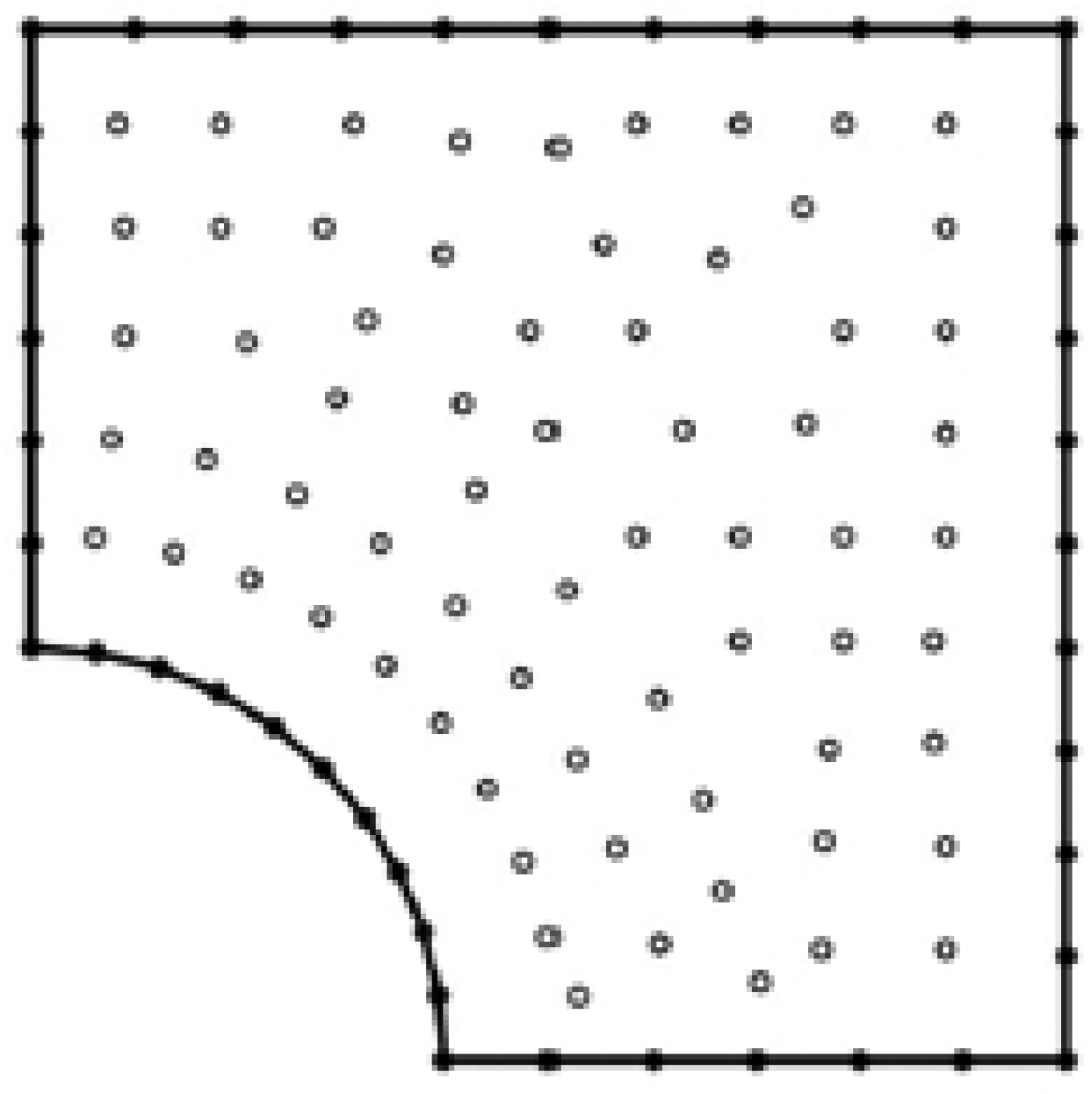
Figure 1. Boundary element model of the considered granular plate.
Fractalfract 07 00214 g001
Figure 2. Distribution of the magneto-thermo-visco-elastic stress σ 11 along x 1 -axis under temperature-dependent and anisotropic effects.
Fractalfract 07 00214 g002
Figure 3. Distribution of the magneto-thermo-visco-elastic stress σ 12 along x 1 -axis under temperature-dependent and anisotropic effects.
Fractalfract 07 00214 g003
Figure 4. Distribution of the magneto-thermo-visco-elastic stress σ 22 along x 1 -axis under temperature-dependent and anisotropic effects.
Fractalfract 07 00214 g004
Figure 5. Distribution of the magneto-thermo-visco-elastic stress σ 11 along x 1 -axis for different values of functionally graded parameter.
Fractalfract 07 00214 g005
Figure 6. Distribution of the magneto-thermo-visco-elastic stress σ 12 along x 1 -axis for different values of functionally graded parameter.
Fractalfract 07 00214 g006
Figure 7. Distribution of the magneto-thermo-visco-elastic stress σ 22 along x 1 -axis for different values of functionally graded parameter.
Fractalfract 07 00214 g007
Figure 8. Distribution of the magneto-thermo-visco-elastic stress σ 11 along x 1 -axis for different values of fractional parameter.
Fractalfract 07 00214 g008
Figure 9. Distribution of the magneto-thermo-visco-elastic stress σ 12 along x 1 -axis for different values of fractional parameter.
Fractalfract 07 00214 g009
Figure 10. Distribution of the magneto-thermo-visco-elastic stress σ 22 along x 1 -axis for different values of fractional parameter.
Fractalfract 07 00214 g010
Figure 11. Distribution of the magneto-thermo-visco-elastic stress σ 11 along x 1 -axis for analytical, FEM, and BEM methods..
Fractalfract 07 00214 g011
Figure 12. Distribution of the magneto-thermo-visco-elastic stress σ 12 along x 1 -axis for analytical, FEM, and BEM methods.
Fractalfract 07 00214 g012
Figure 13. Distribution of the magneto-thermo-visco-elastic stress σ 22 along x 1 -axis for analytical, FEM, and BEM methods.
Fractalfract 07 00214 g013
Table 1. CPU times and iteration number for CA-Arnoldi, D-K, and GMSS.
DiscretizationPreconditioningCA-Arnoldi [44]D-K [45]GMSS [41]
LevelLevelCPU TimeIteration NumberCPU TimeIteration NumberCPU TimeIteration Number
1 (32)00.0660.0760.046
2 (56)00.1880.2280.147
10.1460.1860.15
3 (104)00.54100.6110.49
10.4880.5490.325
20.4250.4670.243
4 (200)02.42132.52171.8611
11.88112.1151.567
21.6571.82101.45
31.461.5271.363
5 (392)010.011512.02197.8813
19.091010.16176.879
28.1999.29156.097
37.2478.48115.825
46.65775.183
6 (776)0421948.32135.915
136.91743.51933.911
234.51541.61730.19
329.61137.71325.77
427.4933.41121.75
525.5729.6919.63
Table 2. Estimating the computational resources needed to model the temperature-dependent FGA rotating granular plate problems.
LBMFEMBEM
Number of nodes52,00050,00050
Number of elements11,00010,00015
CPU time (min)1701802
Memory (MB)1201301
Disc space (MB)2502700
Accuracy of results (%)2.22.01.0
Disclaimer/Publisher’s Note: The statements, opinions and data contained in all publications are solely those of the individual author(s) and contributor(s) and not of MDPI and/or the editor(s). MDPI and/or the editor(s) disclaim responsibility for any injury to people or property resulting from any ideas, methods, instructions or products referred to in the content.