Article

Robust H Controller Design of Switched Delay Systems with Linear Fractional Perturbations by Synchronous Switching of Rule and Sampling Input

1
Department of Marine Engineering, National Kaohsiung University of Science and Technology, Kaohsiung 811, Taiwan
2
Program of Maritime Science and Technology, National Kaohsiung University of Science and Technology, Kaohsiung 811, Taiwan
3
Department of Intelligent Commerce, National Kaohsiung University of Science and Technology, Kaohsiung 824, Taiwan
*
Author to whom correspondence should be addressed.
Fractal Fract. 2022, 6(9), 479; https://doi.org/10.3390/fractalfract6090479
Submission received: 30 July 2022 / Revised: 17 August 2022 / Accepted: 22 August 2022 / Published: 29 August 2022

Abstract

:
In this paper, we propose synchronous switching of rule and input to achieve H performance for an uncertain switched delay system with linear fractional perturbations. Our developed simple scheme utilizes the linear matrix inequality optimization problem to provide a feasible solution for the proposed results; if the optimization problem was feasible, our proposed robust H control could be designed. The feasibility of the optimization problem could be solved using the LMI toolbox of Matlab. In this paper, robust control with sampling is proposed to stabilize uncertain switching with interval time-varying delay and achieve H performance. Interval time-varying delay and sampling were considered instead of constant delay and pointwise sampling. A full-matrix formulation approach is presented to improve the conservativeness of our proposed results. Some numerical examples are demonstrated to show our main contributions.

1. Introduction

It is well known that delay is usually encountered and exists in some engineering problems, such as circuit systems, internal combustion engines, long communication systems, and networked control. Delay often causes instability or bad performance in control systems [1,2,3]. Delayed systems have been applied in aircraft models, engine idle speed control systems, load balancing control systems, networked control systems, power amplifiers in mobile telecommunications, robotized teleoperation, and remote web control of mechanical systems [4,5,6,7,8]. According to [7,9,10], interval time-varying delay would be a more suitable model to present a practical environment for finite speed signal transmission. On the other hand, the dynamic behaviors of switched systems are controlled by several subsystems and use a switching rule to handle switching between those subsystems [11,12]. Switched systems also appear with increasing frequency in aerospace and automotive engineering, biological systems, multi-rate systems, power engineering, robotics, robot mechanical systems, stepper motors, and water quality processing systems [11,12,13,14]. According to [13,14], many complex nonlinear dynamics are witnessed in switched systems based on switching among subsystems, such as multiple limit cycles and chaos. Hence, stability and performance analysis for switched systems with interval time-varying delays has received more consideration by many researchers [13,14,15,16].
Two interesting facts relating to switched systems are: (1) stability in a switched system can be achieved by selecting a suitable switching rule, even when each subsystem is unstable [13,14,15], and (2) the stability of each subsystem cannot guarantee the stability of the entire switched system under an arbitrary switching rule [16]. The average dwell-time method was used to identify the stability of a system under consideration in [17]. In [13,14,15], the stability and performance of switched systems were guaranteed by proposed different design schemes for switching rules. Based on those specific schemes, a simple design rule was developed for continuous and discrete-time switched systems under consideration [18].
In the past, H methods were proposed as a means to diminish the effect of disturbance on the output of systems under consideration [19,20]. In [15], stability in switched time-delay systems could be achieved by using real-time switching. The main disadvantage of this real-time switching is the difficulty of implementation. Hence, a proposed rule for synchronous switching at each sampling instant could be a better approach for control than real-time switching [18]. In [18], it was proposed to use aperiodic sampling instead of the periodic sampling in [21]. However, the pointwise sampling period in [18] would constrain the applicability of the proposed results. Hence, this constraint can be evaluated as relaxing to an upper bound for the sampling period in this paper. In the past, linear fractional perturbations were proposed to present more general forms of uncertainties of systems [22,23]. In [24], a novel inequality was developed to improve conservativeness in relation to the Wirtinger-based one. However, this proposed inequality made it more complicated and difficult to develop and design controller schemes. The main advantages and innovations of our proposed scheme can be highlighted:
  • Robust H control for a switched system with interval time-varying delay and linear fractional perturbations is provided by synchronous switching of rule and input.
  • For simplicity, a full-matrix formulation approach is used to present the developed results. Linear matrix inequality (LMI) optimization results can be performed directly using this approach.
  • The proposed robust controller can confront uncertain switching with interval time-varying delay and sampling. Some upper bounds for sampling and interval time-varying delay can be estimated, as opposed to the pointwise sampling and constant delay in [18].
  • The vector X(t) in the Lyapunov–Krasovskii functional contains possible knowledge regarding our considered system.
The paper is organized as follows. In Section 2, the problem statement for synchronous switching is provided. In Section 3, some numerical examples are provided to show the applicability of the main results. Finally, concluding remarks are in Section 4.

2. Problem Statement

In this paper, we considered the following uncertain switched delay system with linear fractional perturbations:
x ˙ t = A ¯ x 0 σ t x t + A ¯ x 1 σ t x t h t + B ¯ x u σ t u t + B ¯ x w σ t w t ,   t 0 z t = A ¯ z 0 σ t x t + A ¯ z 1 σ t x t h t + B ¯ z u σ t u t + B ¯ z w σ t w t ,   t 0
x t = φ t , t h M ,   0
where A ¯ x 0 σ t = A x 0 σ + A x 0 σ t , A ¯ x 1 σ t = A x 1 σ + A x 1 σ t , B ¯ x u σ t = B x u σ + B x u σ t , B ¯ x w σ t = B x w σ + B x w σ t , A ¯ z 0 σ t = A z 0 σ + A z 0 σ t , A ¯ z 1 σ t = A z 1 σ + A z 1 σ t , B ¯ z u σ t = B z u σ + B z u σ t , B ¯ z w σ t = B z w σ + B z w σ t , x t R n is defined as the state variable, u t R p is defined as the control variable, w t R m is defined as the disturbance variable, z t R q is defined as the output variable, σN is defined as the switching rule and depends on x or t, h(t) > 0 is defined as the time-varying delay satisfying 0 < hmh(t) ≤ hM, h ˙ t hD < 1, hm, where hM and hD are two given positive constants, and the initial condition is φ ∈ C0, where C0 is defined to be a set of continuous functions from [− hM, 0] to R n . A x 0 i , A x 1 i R n × n , B x u i R n × p , B x w i R n × m , A z 0 i , A z 1 i R q × n , B z u i R q × p , and B z w i R q × m , iN, are defined as the given constant matrices. Δ A x 0 i t , Δ A x 1 i t , Δ B x u i t , Δ B x w i t , Δ A z 0 i t , Δ A z 1 i t , Δ B z u i t , and Δ B z w i t , iN, are defined as the uncertain matrices satisfying the following constraints:
Δ A x 0 i t Δ A x 1 i t Δ B x u i t Δ B x w i t = M x i · Δ x i t · N x 0 i N x 1 i N x u i N x w i Δ A z 0 i t Δ A z 1 i t Δ B z u i t Δ B z w i t = M z i · Δ z i t · N z 0 i N z 1 i N z u i N z w i Δ x i t = I Γ x i t Ξ x i 1 Γ x i t ,   Ξ x i Ξ x i T < T
Δ z i t = I Γ z i t Ξ z i 1 Γ z i t ,   Ξ z i Ξ z i T < T
where constant matrices Mxi, Mzi, Nx0i, Nx1i, Nxui, Nzwi, Nz0i, Nz1i, Nzui, Nzwi, Ξxi, and Ξzi, iN, are provided with appropriate dimensions. Perturbed matrices Γxi(t) and Γzi(t), ∀iN, are unknown and satisfy the following conditions [22,23]:
Γxi(t)T · Γxi(t) ≤ I, ∀iN, t ≥ 0,
Γzi(t)T · Γzi(t) ≤ I, ∀iN, t ≥ 0,
Some domains are defined by
Ω i Z i = x R n : x T Z i x 0
where matrices Z i = Z i T R n × n , i = 1, 2, … N, can be obtained from the developed results. The switching domains used in this paper can be defined by the following:
Ω ¯ 1 = Ω 1 ,   Ω ¯ 2 = Ω 2 / Ω ¯ 1 ,   Ω ¯ 3 = Ω 3 / Ω ¯ 1 / Ω ¯ 2 ,     and   Ω ¯ N = Ω N / Ω ¯ 1     / Ω ¯ N 1
We provide the following lemmas to obtain our main results in this paper.
Lemma1.
Suppose that x(t) is a differentiable function from t h 2 ,   t h 1 R n . Then, for a matrix R > 0 and some matrices N1, N2, N3  R 4 n × n , the following inequality is satisfied [24]:
t h 2 t h 1 x ˙ T s R x ˙ s d s δ T t Ω δ t ,
where
δ T t = x T t h 1 x T t h 2 1 h t h 2 t h 1 x T s d s · 2 h 2 t h 2 t h 1 t h 2 s u d u d s
h = h 2 h 1 0
Ω = h · N 1 R 1 N 1 T + 1 3 N 2 R 1 N 2 T + 1 5 N 3 R 1 N 3 T + S y m N 1 Π 1 + N 2 Π 2 + N 3 Π 3
Π 1 = E 4,1 E 4,2 ,   Π 2 = E 4,1 + E 4,2 2 E 4,3 ,   Π 3 = E 4,1 E 4,2 6 E 4,3 + 6 E 4,4 .
Lemma2:
Suppose that x(t) is a differentiable function from t h 2 ,   t h 1 R n with constants 0 ≤ hm ≤ hM. Then, for two matrices R > 0 and S, satisfying [25]
[ R S * R ] > 0 ,
the following inequality holds:
( h M h m ) t h M t h m x ˙ T ( s ) R x ˙ ( s ) d s
[ x ( t h ( t ) ) x ( t h M ) x ( t h m ) x ( t h ( t ) ) ] T [ R S * R ] [ x ( t h ( t ) ) x ( t h M ) x ( t h m ) x ( t h ( t ) ) ] = Z 1 T ( t ) Ω 1 Z 1 ( t ) ,
where the time-varying function  h ( t ) [ h m , h M ] ,
Z 1 T ( t ) = [ x T ( t h ( t ) ) x T ( t h m ) x T ( t h M ) ] ,
Ω 1 = [ 2 R + S + S T R S R S T * R S T * * R ] .
Lemma3.
With 0 α i 1 , i N _ , i = 1 N α i = 1 , Z i = Z i T n × n , i N _ , and condition [18]
i = 1 N α i Z i > 0 ,
We obtain the following results
i = 1 N Ω ¯ i = n   and   Ω ¯ i Ω ¯ j = Φ ,   i j ,
x T ( t ) Ζ i x ( t ) 0   and   σ ( x ( t ) ) = i ,   x ( t ) Ω ¯ i ,
where  Ω ¯ i is shown in (3b).
Remark 1.
With the proposedaffineBessel–Legendre inequality in [26], the used inequality in Lemma 1 of this paper is a special case for  N = 2 . Our proposed results in this papercould be improved by using more complicated Lyapunov–Krasovskii functional in the future. The proposed inequality in Lemma 2 is applied to reduce conservativeness regarding the interval time-varying delay in this paper [26]. It is interesting to note thatthe computational complexity for the feasibility of LMI conditions (LMIs) is highly dependent on both the dimensions of the LMIs and the number of decision variables. Based on the constrained number of decision variables, it would be important to propose a useful tool to formulate these LMIs and use the LMI toolbox of Matlab for feasibility. Hence, a full-matrix formulation approach is used to serve this purpose.
Remark 2.
From Lemma 3 and the definition in (3b), uniqueness and compactness regarding our proposed state feedback control can be achieved to verify our results.
It is well known that the state of a system may be sampled and data obtained by some electronic devices. In this paper, the sampling instants are defined by 0 = T 0 < T 1 < T 2 < . The following function can be defined from the sampling period:
τ ( t ) = t T k , t [ T k , T k + 1 ) ,
where τ k = T k + 1 T k and τ M = max k = 0 k = τ k . From the above formulation, we can provide the following conditions:
0 τ ( t ) τ M ,   t 0 ,   and   T k = t τ ( t ) ,   t [ T k , T k + 1 ) .
The synchronous sampling switching rule can be provided as follows:
when   x ( T k ) Ω ¯ i ,   σ ( t ) = i ,     t [ T k , T k + 1 ) ,
and sampling input can be defined as:
when   x ( T k ) Ω ¯ i ,   u ( t ) = K i x ( T k ) ,     t [ T k , T k + 1 ) ,
where Ω ¯ i is shown in (3). In (4) and (5), the switching rule and sampling input are switched synchronously at each sampling instant.
Definition 1.
With system (1) with (2) and synchronous switching of rule and input in (4), assume:
(i)
With  w ( t ) = 0 , system (1) with (2) is asymptotically stable due to the synchronous switching of rule and input in (4) and (5).
(ii)
With a zero initial state (i.e.,  φ ( t ) = 0 , h M t 0 ),    w ( t )  and  z ( t )  are satisfied by the following condition:
0 z T ( t ) z ( t ) d t γ 2 0 w T ( t ) w ( t ) d t , w 0 ,
for constants  > 0  and  γ > 0 . If  = , the disturbance  w  should be defined by  L 2 ( 0 , ) .
Then, we can say that system (1) with (2) stabilizes at  H  performance  γ  according to switchingrule in (4) with  Z i  and input in (5) with  K i .
The following notations can be defined before the presentation of the main results:
Π 1 = E 4 , 1 E 4 , 2 ,   Π 2 = E 4 , 1 + E 4 , 2 2 E 4 , 3 ,   Π 3 = E 4 , 1 E 4 , 2 6 E 4 , 3 + 6 E 4 , 4 ,
Δ 1 = [ E 16 , 1 T   h m E 16 , 7   T h M E 16 , 8 T   ( h M h m ) E 16 , 9 T   τ M E 16 , 10 T   0.5 h m 2 E 16 , 11 T
0.5 h M 2 E 16 , 12 T   0.5 ( h M h m ) 2 E 16 , 13 T   0.5 τ M 2 E 16 , 14 T ] T ,
Δ 2 = [ E 16 , 16 T     ( E 16 , 1 E 16 , 3 ) T   ( E 16 , 1 E 16 , 4 ) T
( E 16 , 3 E 16 , 4 ) T     ( E 16 , 1 E 16 , 6 ) T   h m ( E 16 , 7 E 16 , 3 ) T
h M ( E 16 , 8 E 16 , 4 ) T   ( h M h m ) ( E 16 , 9 E 16 , 4 ) T   τ M ( E 16 , 10 E 16 , 6 ) T ] T ,
Λ 1 = [ E 16 , 1 T E 16 , 3 T E 16 , 7 T E 16 , 11 T ] T ,   Λ 2 = [ E 16 , 1 T E 16 , 4 T E 16 , 8 T E 16 , 12 T ] T ,
Λ 3 = [ E 16 , 3 T E 16 , 4 T E 16 , 9 T E 16 , 13 T ] T ,   Λ 4 = [ E 16 , 1 T E 16 , 6 T E 16 , 10 T E 16 , 14 T ] T ,
Λ 5 = [ E 16 , 2 T E 16 , 3 T E 16 , 4 T ] T ,   Λ 6 = [ E 16 , 5 T E 16 , 1 T E 16 , 6 T ] T .
An LMI optimization result is investigated in order to achieve asymptotic stability and H performance for the system under consideration according to the synchronous switching of rule and input given in (4) and (5).
Theorem1.
Suppose there exist constants  η , 0 α i 1 , i N _ , with i = 1 N α i = 1 , such that the LMI optimization problem:
minimize γ ¯ ,
subject to
i = 1 N α i Ζ ^ i > 0 ,
[ R ^ 5 S ^ 1 * R ^ 5 ] > 0 ,
[ R ^ 6 S ^ 2 * R ^ 6 ] > 0 ,
Ψ ^ i = [ Ψ ^ 11 i Ψ ^ 12 i Ψ ^ 13 i 0 Ψ ^ 15 i Ψ ^ 16 i Ψ ^ 17 * I 0 ε i M z i 0 0 0 * * ε i I 0 ε i Ξ x i 0 0 * * * ε i I 0 ε i Ξ z i 0 * * * * ε i I 0 0 * * * * * ε i I 0 * * * * * * Ψ ^ 77 ] < 0 ,   i N _ ,
where
Ψ ^ 11 i = S y m ( Δ 2 T P ^ Δ 1 + ( η E 16 , 1 T + E 16 , 16 T ) Γ ^ 1 i ) + Ω ^ 1 + Ω ^ 2 + Ω ^ 3 ,
Ψ ^ 12 i = Γ ^ 2 i T ,   Ψ ^ 13 i = ε i ( η E 16 , 1 T + E 16 , 16 T ) M x i ,
Ψ ^ 15 i T = [ N x 0 i U ^ T   N x 1 i U ^ T   0   0 N x u i K ^ i   0   0   0   0   0   0   0   0   0   N x w i   0 ] ,
Ψ ^ 16 i T = [ N z 0 i U ^ T   N z 1 i U ^ T   0   0 N z u i K ^ i   0   0   0   0   0   0   0   0   0   N z w i   0 ] ,
Ψ ^ 17 = [ h m Λ 1 T N ^ 11   h m Λ 1 T N ^ 12   h m Λ 1 T N ^ 13   h M Λ 2 T N ^ 21   h M Λ 2 T N ^ 22
h M Λ 2 T N ^ 23   h M h m Λ 3 T N ^ 31   h M h m Λ 3 T N ^ 32   h M h m Λ 3 T N ^ 33
τ M Λ 4 T N ^ 41   τ M Λ 4 T N ^ 42   τ M Λ 4 T N ^ 43 ] ,
Ψ ^ 77 = d i a g [ R ^ 1   3 R ^ 1   5 R ^ 1   R ^ 2   3 R ^ 2   5 R ^ 2   R ^ 3   3 R ^ 3   5 R ^ 3   R ^ 4   3 R ^ 4   5 R ^ 4 ] ,
Ω ^ 1 = i = 1 3 S y m ( Λ 1 T N ^ 1 i Π i Λ 1 + Λ 2 T N ^ 2 i Π i Λ 2 + Λ 3 T N ^ 3 i Π i Λ 3 + Λ 4 T N ^ 4 i Π i Λ 4 ) ,
Ω ^ 2 = Λ 5 T [ 2 R ^ 5 + S ^ 1 + S ^ 1 T R ^ 5 S ^ 1 R ^ 5 S ^ 1 T * R ^ 5 S ^ 1 T * * R ^ 5 ] Λ 5
+ Λ 6 T [ 2 R ^ 6 + S ^ 2 + S ^ 2 T R ^ 6 S ^ 2 R ^ 6 S ^ 2 T * R ^ 6 S ^ 2 T * * R ^ 6 ] Λ 6 ,
Ω ^ 3 = E 16 , 1 T Q ^ 0 E 16 , 1 ( 1 h D ) ¯ E 16 , 2 T Q ^ 4 E 16 , 2 E 16 , 3 T ( Q ^ 1 Q ^ 3 ) E 16 , 3 E 16 , 4 T ( Q ^ 2 + Q ^ 3 ) E 16 , 4
E 16 , 6 T Q ^ 5 E 16 , 6 + E 16 , 5 T Ζ ^ i E 16 , 5 γ ¯ E 16 , 15 T E 16 , 15 η S y m ( E 16 , 1 T U ^ T E 16 , 16 )
E 16 , 16 T [ U ^ + U ^ T R ^ 0 ] E 16 , 16 ,
Q ^ 0 = Q ^ 1 + Q ^ 2 + Q ^ 4 + Q ^ 5 ,
R ^ 0 = h m R ^ 1 + h M R ^ 2 + ( h M h m ) ( R ^ 3 + R ^ 5 ) + τ M ( R ^ 4 + R ^ 6 ) ,
Γ ^ 1 i = [ A x 0 i U ^ T   A x 1 i U ^ T   0   0 B x u i K ^ i   0   0   0   0   0   0   0   0   0   B x w i   0 ] ,
Γ ^ 2 i = [ A z 0 i U ^ T A z 1 i U ^ T   0   0 B z u i K ^ i   0   0   0   0   0   0   0   0   0   B z w i   0 ] ,
is feasible with constants  γ ¯ > 0 ,  ε i > 0 ,  i N _ , a nonsingular matrix  U ^ n × n ,  P ^ > 0 9 n × 9 n ,  Q ^ i > 0 ,  R ^ j > 0 n × n ,  i 5 _ ,  j 6 _ , matrices  Z ^ i = Z ^ i T n × n ,  i N _ , and  S ^ 1 ,   S ^ 2 n × n ,  N ^ i j 4 n × n ,  i 4 _ ,   j 3 _ ,  K ^ i p × n ,  i N _ . Then, system (1) with (2) stabilizes with  H  performance  γ = γ ¯  via switching rule in (4) with  Ζ i = U ^ 1 Ζ ^ i U ^ T  and input in (5) with  K i = K ^ i U ^ T .
Proof.
In this paper, we define the Lyapunov–Krasovskii functional as follows:
V ( x ( t ) ) = X T ( t ) P X ( t ) + t h m t x T ( s ) Q 1 x ( s ) d s + t h M t x T ( s ) Q 2 x ( s ) d s + t h M t h m x T ( s ) Q 3 x ( s ) d s + t h ( t ) t x T ( s ) Q 4 x ( s ) d s + t τ M t x T ( s ) Q 5 x ( s ) d s + h m 0 t + s t x ˙ T ( u ) R 1 x ˙ ( u ) d u d s + h M 0 t + s t x ˙ T ( u ) R 2 x ˙ ( u ) d u d s + h M h m t + s t x ˙ T ( u ) ( R 3 + R 5 ) x ˙ ( u ) d u d s + τ M 0 t + s t x ˙ T ( u ) ( R 4 + R 6 ) x ˙ ( u ) d u d s ,
where
P = U ^ ^ ^ P ^ U ^ ^ ^ T > 0 ,   U ^ ^ ^ = d i a g [ U   U   U   U   U   U   U   U   U ] ,   U = U ^ 1 ,
Q i = U Q ^ i U T > 0 ,   R j = U R ^ j U T > 0 ,   i 5 _ ,   j 6 _ ,
X ( t ) = [ x T ( t )   t h m t x T ( s ) d s   t h M t x T ( s ) d s   t h M t h m x T ( s ) d s   t τ M t x T ( s ) d s   t h m t t h m s x T ( u ) d u d s
  t h M t t h M s x T ( u ) d u d s   t h M t h m t h M s x T ( u ) d u d s   t τ M t t τ M s x T ( u ) d u d s ] T .
The derivatives of V ( x t ) for system (1) with (2)–(4) have
V ˙ ( x ( t ) ) = X ˙ T ( t ) P X ( t ) + X T ( t ) P X ˙ ( t ) + x T ( t ) Q 0 x ( t ) ( 1 h ˙ ( t ) ) ¯ x T ( t h ( t ) ) Q 4 x ( t h ( t ) ) x T ( t h m ) ( Q 1 Q 3 ) x ( t h m ) x T ( t h M ) ( Q 2 + Q 3 ) x ( t h M ) x T ( t τ M ) Q 5 x ( t τ M ) + x ˙ T ( t ) R 0 x ˙ ( t ) [ ( t ) + t h M t h m x ˙ T ( s ) R 5 x ˙ ( s ) d s + t τ M t x ˙ T ( s ) R 6 x ˙ ( s ) d s ] ,
where
Q 0 = Q 1 + Q 2 + Q 4 + Q 5 ,   R 0 = h m R 1 + h M R 2 + ( h M h m ) ( R 3 + R 5 ) + τ M ( R 4 + R 6 ) ,
( t ) = t h m t x ˙ T ( s ) R 1 x ˙ ( s ) d s + t h M t x ˙ T ( s ) R 2 x ˙ ( s ) d s
+ t h M t h m x ˙ T ( s ) R 3 x ˙ ( s ) d s + t τ M t x ˙ T ( s ) R 4 x ˙ ( s ) d s .
Defining
Y ( t ) = [ x T ( t )   x T ( t h ( t ) )   x T ( t h m )   x T ( t h M ) )   x T ( t τ ( t ) )   x T ( t τ M )
1 h m t h m t x T ( s ) d s     1 h M t h M t x T ( s ) d s   1 h M h m t h M t h m x T ( s ) d s   1 τ M t τ M t x T ( s ) d s
2 h m 2 t h m t t h m s x T ( u ) d u d s   2 h M 2 t h M t t h M s x T ( u ) d u d s  
2 ( h M h m ) 2 t h M t h m t h M s x T ( u ) d u d s     2 τ M 2 t τ M t t τ M s x T ( u ) d u d s   w T ( t )   x ˙ T ( t ) ] T ,
Γ 1 i ( t ) = [ A ¯ x 0 i ( t )   A ¯ x 1 i ( t )   0   0 B ¯ x u i ( t ) K i   0   0   0 0 0   0   0   0   0   B ¯ x w i ( t )   0 ] ,
Γ 2 i ( t ) = [ A ¯ z 0 i ( t )   A ¯ z 1 i ( t )   0   0 B ¯ z u i ( t ) K i   0   0   0 0 0   0   0   0   0   B ¯ z w i ( t )   0 ] ,
we have
X ( t ) = Δ 1 Y ( t ) ,
X ˙ ( t ) = Δ 2 Y ( t ) ,
where Δ 1 and Δ 2 were shown in (6), respectively. By using Lemma 1 and ( t )  given in (13), we can provide the following condition:
( t ) Y T ( t ) Ω 1 Y ( t ) ,
where
Ω 1 = h m Λ 1 T 1 Λ 1 + h M Λ 2 T 2 Λ 2 + ( h M h m ) Λ 3 T 3 Λ 3 + τ M Λ 4 T 4 Λ 4 + Ω ¯ 1 ,
i = N i 1 R i 1 N i 1 T + 1 3 N i 2 R i 1 N i 2 T + 1 5 N i 3 R i 1 N i 3 T ,   i 4 _ ,
Ω ¯ 1 = i = 1 3 S y m ( Λ 1 T N 1 i Π i Λ 1 + Λ 2 T N 2 i Π i Λ 2 + Λ 3 T N 3 i Π i Λ 3 + Λ 4 T N 4 i Π i Λ 4 ) ,
N i j 4 n × n . , i 4 _   j 3 _ , will be chosen, matrices Λ i and Π j , i 4 _ ,   j 3 _ , are shown in (6). By using Lemma 2, we obtain the following inequality:
t h M t h m x ˙ T ( s ) R 5 x ˙ ( s ) d s + t τ M t x ˙ T ( s ) R 6 x ˙ ( s ) d s Y T ( t ) Ω 2 Y ( t ) ,
where
Ω 2 = Λ 5 T [ 2 R 5 + S 1 + S 1 T R 5 S 1 R 4 S 1 T * R 5 S 1 T * * R 5 ] Λ 5
+ Λ 6 T [ 2 R 6 + S 2 + S 2 T R 6 S 2 R 5 S 2 T * R 6 S 2 T * * R 6 ] Λ 6 ,
Λ 5 and Λ 6 are shown in (6). By the system (1) with conditions (2)–(5), and σ ( x ( t ) ) = i ,   t [ T k , T k + 1 ) , we have
S y m ( ( x ˙ ( t ) + Γ 1 i ( t ) Y ( t ) ) T U T ( η x ( t ) + x ˙ ( t ) ) ) = 0 .  
Via the conditions in (13)–(16), the following results can be achieved with γ ¯ = γ 2 :
V ˙ ( x ( t ) ) + z T ( t ) z ( t ) γ 2 w T ( t ) w ( t ) Y T ( t ) Π i ( t ) Y ( t ) ,
where
Π i ( t ) = Δ 2 T P Δ 1 + Δ 1 T P Δ 2 + Ω 1 + Ω 2 + Ω 3 + S y m ( ( η E 16 , 1 T + E 16 , 16 T ) U Γ 1 i ( t ) ) + Γ 2 i T ( t ) Γ 2 i ( t ) ,  
Ω 3 = E 16 , 1 T Q 0 E 16 , 1 ( 1 h D ) ¯ E 16 , 2 T Q 4 E 16 , 2 E 16 , 3 T ( Q 1 Q 3 ) E 16 , 3
E 16 , 4 T ( Q 2 + Q 3 ) E 16 , 4 E 16 , 6 T Q 5 E 16 , 6 γ 2 E 16 , 15 T E 16 , 15
η S y m ( E 16 , 1 T U E 16 , 16 ) E 16 , 16 T [ U + U T R 0 ] E 16 , 16 .
By the following definition
Σ i ( t ) = [ Σ 1 i ( t ) Γ 2 i T ( t ) * I ] = [ Σ ¯ 1 i Γ ¯ 2 i T * I ] + Δ x z i ( t ) ,
Σ 1 i ( t ) = Δ 2 T P Δ 1 + Δ 1 T P Δ 2 + Ω 1 + Ω 2 + Ω 3 + S y m ( ( η E 16 , 1 T + E 16 , 16 T ) U Γ 1 i ( t ) ) ,
Σ ¯ 1 i = Δ 2 T P Δ 1 + Δ 1 T P Δ 2 + Ω 1 + Ω 2 + Ω 3 + S y m ( ( η E 16 , 1 T + E 16 , 16 T ) U Γ ¯ 1 i ) ,
Γ ¯ 1 i = [ A 0 i   A 1 i   0   0 B u i K i   0   0 0 0   0   0   0   0   0   B w i   0 ] ,
Γ ¯ 2 i = [ A z 0 i   A z 1 i   0   0 B z u i K i   0   0 0 0   0   0   0   0   0   B z w i   0 ] ,
Δ x z i ( t ) = S y m ( [ ( η E 16 , 1 T + E 16 , 16 T ) U M x i 0 0 M z i ] [ Δ x i ( t ) 0 0 Δ z i ( t ) ] N x z i ) ,
N x z i = [ N x 0 i   N x 1 i   0   0 N x u i K i   0   0   0   0   0   0   0   0   0   N x w i   0 N z 0 i   N z 1 i   0   0 N z u i K i   0   0   0   0   0   0   0   0   0   N z w i   0 ] ,
we can obtain the following matrices:
Ψ i = [ Σ ¯ 1 i Γ ¯ 2 i T ε i ( η E 16 , 1 T + E 16 , 16 T ) U M x i 0 Ψ 15 i Ψ 16 i * I 0 ε i M y i 0 0 * * ε i I 0 ε i Ξ x i 0 * * * ε i I 0 ε i Ξ y i * * * * ε i I 0 * * * * * ε i I ] ,
where
Ψ 15 i T = [ N x 0 i   N x 1 i   0   0 N x u i K i   0   0   0   0   0   0   0   0   0   N x w i   0 ] ,
Ψ 16 i T = [ N z 0 i   N z 1 i   0   0 N z u i K i   0   0   0   0   0   0   0   0   0   N z w i   0 ] .
By using the switching rule in (4) with (8) and Ζ ^ i = U ^ Ζ i U ^ T , we have
i = 1 N α i Ζ i > 0 .
When x ( T k ) Ω ¯ i with (21) and Lemma 3, we have
x T ( T k ) Ζ i x ( T k ) = x T ( t τ ( t ) ) Ζ i x ( t τ ( t ) ) 0 ,   σ ( x ( t ) ) = i ,     t [ T k , T k + 1 ) .
With (10), (22), and
U ^ ^ = d i a g [ U U U U U U U   U   U   U   U   U   U U   I U I I I I I ] ,
U ^ = U 1 ,   U ^ ^ ^ = d i a g [ U   U   U   U   U   U   U   U   U ] ,   P ^ = U ^ ^ ^ 1 P U ^ ^ ^ T > 0 ,
S ^ i = U 1 S i U T ,   Q ^ i = U 1 Q i U T > 0 ,   R ^ i = U 1 R i U T > 0 ,   Ζ ^ i = U 1 Ζ i U T ,
We can show the following condition:
U ^ ^ 1 Ψ i U ^ ^ T < 0 .
The above condition also implies Ψ i < 0 in (20). According to the perturbation decomposition in [22,23] and the Schur complement in [27] with condition (20), we can derive the following condition from (18) and (19):
Σ i ( t ) < 0 ,   Π i ( t ) < 0 .
With w ( t ) = 0 , (17), and Π i ( t ) < 0 , we have
V ˙ ( x ( t ) ) < 0 ,   x ( t ) 0 ,     t [ T k , T k + 1 ) .  
The system (1) with (2)–(5) and w ( t ) = 0 is asymptotically stable. Using condition (17), Π i ( t ) < 0 , and a time integral from 0 to > 0 , we have
V ( x ( ) ) V ( φ ) + 0 z T ( t ) z ( t ) d t γ 2 0 w T ( t ) w ( t ) d t .
With a zero initial state (i.e., φ ( t ) = 0 , h M t 0 ), we can obtain the following result:
V ( φ ( 0 ) ) = 0 ,   V ( x ( ) ) 0 .
The following condition can be achieved:
0 z T ( t ) z ( t ) d t γ 2 0 w T ( t ) w ( t ) d t ,   w 0 ,
for > 0 and γ > 0 . The proof is completed. □
For an arbitrary signal σ ( t ) with capturing at each sampling instant, the state feedback sampling input can be provided:
when   σ ( T k ) = i ,   u ( t ) = K i x ( T k ) ,     t [ T k , T k + 1 ) .
With sampling input in (23), delay-dependent LMI optimization can be developed.
Corollary 1.
Suppose there exists a constant  η , such that the following LMI optimization problem:
minimize γ ¯ ,
subject to conditions (6c)–(6d)
Ψ ^ ^ i j = [ Ψ ^ ^ 11 i j Ψ ^ ^ 12 i j Ψ ^ 13 i 0 Ψ ^ ^ 15 i j Ψ ^ ^ 16 i j Ψ ^ 17 * I 0 ε i M z i 0 0 0 * * ε i I 0 ε i Ξ x i 0 0 * * * ε i I 0 ε i Ξ z i 0 * * * * ε i I 0 0 * * * * * ε i I 0 * * * * * * Ψ ^ 77 ] < 0 ,   i N _ ,   j N _ ,
where
Ψ ^ ^ 11 i j = S y m ( Δ 2 T P ^ Δ 1 + ( η E 16 , 1 T + E 16 , 16 T ) Γ ^ ^ 1 i j ) + Ω ^ 1 + Ω ^ 2 + Ω ^ ^ 3 ,   Ψ ^ ^ 12 i j = Γ ^ ^ 2 i j T ,
Ψ ^ ^ 15 i j T = [ N x 0 i U ^ T N x u i K ^ j   N x 1 i U ^ T   0   0   0   0   0   0   0   0   0   N x w i   0 ] ,
Ψ ^ ^ 16 i j T = [ N z 0 i U ^ T N z u i K ^ j   N z 1 i U ^ T   0   0   0   0   0   0   0   0   0   N z w i   0 ] ,
Ω ^ ^ 3 = E 16 , 1 T Q ^ 0 E 16 , 1 ( 1 h D ) ¯ E 16 , 2 T Q ^ 4 E 16 , 2 E 16 , 3 T ( Q ^ 1 Q ^ 3 ) E 16 , 3 E 16 , 4 T ( Q ^ 2 + Q ^ 3 ) E 16 , 4
E 16 , 6 T Q ^ 5 E 16 , 6 γ ¯ E 16 , 15 T E 16 , 15 η S y m ( E 16 , 1 T U ^ T E 16 , 16 ) E 16 , 16 T [ U ^ + U ^ T R ^ 0 ] E 16 , 16 ,
Ψ ^ 13 i ,   Ψ ^ 17 ,   Ψ ^ 77 ,   Ω ^ 1 ,   Ω ^ 2 ,   Q ^ 0 ,   and R ^ 0   defined   in   the   Theorem   1 ,  
Γ ^ ^ 1 i j = [ A x 0 i U ^ T   A x 1 i U ^ T   0   0 B x u i K ^ j   0   0   0   0   0 0 0   0   0   B x w i   0 ] ,
Γ ^ ^ 2 i j = [ A z 0 i U ^ T   A z 1 i U ^ T   0   0 B z u i K ^ j   0   0   0   0   0 0 0   0   0   B z w i   0 ] ,
is feasible with constants  γ ¯ > 0 ,  ε i > 0 ,  i N _ , a nonsingular matrix  U ^ n × n ,  P ^ > 0 9 n × 9 n ,  Q ^ i > 0 ,  R ^ j > 0 n × n ,  i 5 _ ,  j 6 _ , and matrices  S ^ 1 ,   S ^ 2 n × n ,  N ^ i j 4 n × n ,  i 4 _ ,   j 3 _ ,  K ^ i p × n ,  i N _ . Then, system (1) with (2) stabilizes with  H  performance  γ = γ ¯  via the sampling input (23) with  K i = K ^ i U ^ T .
Proof.
This proof can be completed by selecting the matrices Z ^ i = 0 , i N _ in Theorem 1. □
Remark 3.
For Q 4 = 0 ( Q ^ 4 = 0 ) in the Lyapunov–Krasovskii functional (12), the proposed conditions in Theorem 1 and Corollary 1 are independent of h D . Hence, if the parameter h D is larger than 1 or unknown, the results developed in this paper are valid for Q ^ 4 = 0 .
Remark 4.
In [18], aperiodic sampling with a pointwise sampling period was investigated to obtain the H performance of a switched delay system. In this paper, we consider the H performance of a switched delay system with an interval sampling period. More flexible and practical results can be provided to guarantee the performance of the considered system [18].
Remark 5.
In this paper, bigger values of τ M , h M , h M h m can provide better results with reduced conservativeness regarding our developed results. A smaller value for γ ( γ ¯ ) can provide a better result regarding disturbance attenuation in the switched delay system.
Remark 6.
The uncertainties presented in (2) are said linear fractional perturbations [22,23]. These perturbations were confronted in many practical systems, such as fuzzy T-S systems, neural networks, neutral systems and switched systems. The proposed robust H control can be used to achieve the performance requirements of a system with linear fractional perturbations in (2).

3. Some Numerical Examples

To show the efficiency of our proposed results, two examples from [18] can be used to demonstrate the main contributions in this paper.
Example 1.
A switched delay system (1) with (2) and the parameters given is considered:
N = 2 ,   h m = 1 ,   h M = 1.2 ,   τ M = 0.3 ,
A x 01 = [ 1.1 0.1 0.2 1 ] ,   A x 02 = [ 1.2 0 0.1 1.1 ] ,   A x 11 = [ 0.9 0.05 0.2 1 ] ,
A x 12 = [ 1 0.1 0.25 1 ] ,   B x w 1 = [ 0.2 0.01 ] ,   B x w 2 = [ 0.2 0.02 ] ,   B x u 1 = [ 1 0.1 ] ,   B x u 2 = [ 1 0.1 ] ,
A z 01 = [ 1 0 ] ,   A z 02 = [ 0.8 0.1 ] ,   A z 11 = [ 0.8 0.6 ] ,   A z 12 = [ 0.2 1 ] ,
B z w 1 = B z w 2 = 0.5 ,   B z u 1 = B z u 2 = 0.3 ,
M x i = [ 0.01 0 0 0.02 ] ,   M z i = 0.01 ,   N x 0 i = [ 0.1 0 0 0 ] ,   N x 1 i = [ 0 0 0 0.1 ] ,
N x w i = N x u i = 0 ,   N z w i = N z u i = 0 ,   Ξ x i = 0.1 I ,   Ξ z i = 0.1 ,
N z 0 i = N z 1 i = [ 0.1 0 ] ,   i = 1 , 2 .
By using the proposed synchronous switching (4) of rule and input with  1   h ( t ) 1.2    and  τ k 0.3 ,    k, the LMI optimization problem in (7) of Theorem 1 with  η = 1  and  α 1 = α 2 = 0.5  is feasible with
γ ¯ = 0 . 268 , K ^ 1 = [ 11 . 9239   4 . 6429 ] , K ^ 2 = [ 16 . 9141   6 . 7406 ] ,
U ^ = [ 5.3986 1.9342 0.6831 2.3326 ] , Ζ ^ 1 = [ 8.1649 3.4668 3.4668 0.6176 ] , Ζ ^ 2 = [ 12.3651 5.0374 5.0374 2.0327 ] .
The switched delaysystem in (1) with (2) and (24) is asymptotically stabilizable by the following switching rule:
σ ( x ( t ) ) = { 1 , x ( T k ) Ω ¯ 1 , 2 , x ( T k ) Ω ¯ 2 ,     t [ T k , T k + 1 ) ,
where
Ω ¯ 1 = Ω 1 , Ω ¯ 2 = Ω 2 \ Ω ¯ 1 = 2 \ Ω ¯ 1 ,
Ζ i = U ^ 1 Ζ ^ i U ^ T , i = 1 , 2 ,
with
Ω 1 = { x = [ x 1 x 2 ] T 2 : x T Ζ 1 x = 0.1216 x 1 2 0.453 x 1 x 2 + 0.0296 x 2 2 0 } ,
Ω 2 = { x = [ x 1 x 2 ] T 2 : x T Ζ 2 x = 0.2316 x 1 2 + 0.459 x 1 x 2 + 0.2193 x 2 2 0 } ,
and control input given as follows:
u ( t ) = { K 1 x ( T k ) , x ( T k ) Ω ¯ 1 , K 2 x ( T k ) , x ( T k ) Ω ¯ 2 ,     t [ T k , T k + 1 ) ,  
with
K 1 = K ^ 1 U ^ T = [ 1.6709   1.5011 ] , K 2 = K ^ 2 U ^ T = [ 2.3436   2.2034 ] .
We conclude that system (1) with (2) and (24) stabilizes with  H  performance  γ = γ ¯ = 0 . 5177  using the switching rule in (25) and sampling input in (26) with  K i = K ^ i U ^ T in (27).
Some comparisons are made in Table 1 to show the improvement using the proposed results. A switched system with interval time-varying delay  1 h ( t ) 1.2 , instead of constant delay  h ( t ) = h = 1  as in [18], can be investigated. Interval sampling of  0 < τ i 0.3 ,instead of pointwise sampling  τ i = 0.2  and  τ j = 0.3  for some values i and j as in [18], can be guaranteed. The reduced conservativeness and easy implementation of the proposed synchronous switching of switching rule and sampling input can be observed from this numerical example.
Example 2.
Consider a switched delay system (1) with (2) and parameters as follows:
N = 2 ,   h m = 3 ,   h M = 3.5 ,   τ M = 0.1 ,
A x 01 = [ 1.1 0 0.2 0.25 ] ,   A x 02 = [ 0.35 0.1 0 1.1 ] ,   A x 11 = [ 0.6 0.1 0.2 0.2 ] ,
A x 12 = [ 0.3 0.1 0.1 0.6 ] ,   A z 01 = [ 0.1 0.1 0.1 0.1 ] ,   A z 02 = [ 0.1 0.1 0.1 0 , 1 ] ,
A z 11 = [ 0.1 0.1 0.1 0.1 ] ,   A z 12 = [ 0.1 0.1 0.1 0.1 ] ,   B x w 1 = B x w 2 = [ 0.2 0 0 0.3 ] ,
B x u 1 = B x u 2 = [ 0.2 0 0 0.3 ] ,   B z w 1 = B z w 2 = [ 0.2 0 0 0.3 ] ,
M x i = N x 0 i = [ 0.1 0 0 0.1 ] ,   N x 1 i = [ 0 0.1 0.1 0 ] ,
N x wi = [ 0.1 0.1 0 0 ] ,   N x u 1 = N x u 2 = [ 0 0 0.1 0.1 ] ,
B z u i = M zi = N z 0 i = N z 1 i = Ξ zi = 0 ,   Ξ x i = 0.01 ,   i = 1 , 2 .
Case 1.
By using the proposed synchronous switching (4) of rule and input with  3   h ( t ) 3.5 and τ k 0.1 ,   k, the LMI optimization problem in (6) of Theorem 1 with  η = 1  and  α 1 = α 2 = 0.5  is feasible with
γ ¯ = 0 . 0967 ,   K ^ 1 = [ 7.4486 4.3961 5.1354 2.6515 ] ,   K ^ 2 = [ 8.4781 0.2349 4.9547 12.7028 ] ,
U ^ = [ 8.0691 0.4708 0.0674 19.5961 ] ,   Ζ ^ 1 = [ 11.3692 2.8855 2.8855 29.8478 ] ,   Ζ ^ 2 = [ 10.6848 2.7967 2.7967 30.615 ] .
The switched delaysystem in (1) with (2) and (28) is asymptotically stabilizable using the following switching rule:
σ ( x ( t ) ) = { 1 , x ( T k ) Ω ¯ 1 , 2 , x ( T k ) Ω ¯ 2 ,     t [ T k , T k + 1 ) ,
where
Ω ¯ 1 = Ω 1 , Ω ¯ 2 = Ω 2 \ Ω ¯ 1 = 2 \ Ω ¯ 1 ,
Ζ i = U ^ 1 Ζ ^ i U ^ T , i = 1 , 2 , with
Ω 1 = { x = [ x 1 x 2 ] T 2 : x T Ζ 1 x = 0.1723 x 1 2 + 0.0444 x 1 x 2 0.0779 x 2 2 0 } ,
Ω 2 = { x = [ x 1 x 2 ] T 2 : x T Ζ 2 x = 0.1618 x 1 2 0.0436 x 1 x 2 + 0.0799 x 2 2 0 } ,
and control input is given as follows:
u ( t ) = { K 1 x ( T k ) , x ( T k ) Ω ¯ 1 , K 2 x ( T k ) , x ( T k ) Ω ¯ 2 ,     t [ T k , T k + 1 ) ,
with
K 1 = K ^ 1 U ^ T = [ 0.9364 0.2276 0.6445 0.1375 ] , K 2 = K ^ 2 U ^ T = [ 1.0502 0.0084 0.5763 0.6462 ] .
We conclude that system (1) with (2) and (28) stabilizes with  H  performance  γ = γ ¯ = 0 . 311 using switching rule in (29) and sampling input in (30) with  K i = K ^ i U ^ T in (31).
Case 2.
In this case, we assume that  σ ( t )  is arbitrary and captured at each sampling instant. Using the above statement in Theorem 1 with Corollary 1, the system (1) with (2) and (28) is stabilized by the following switching input:
u ( t ) = { K 1 x ( T k ) , σ ( T k ) = 1 , K 2 x ( T k ) , σ ( T k ) = 2 ,     t [ T k , T k + 1 ) ,  
with  γ ^ = 0 . 3819 ,
K 1 = K ^ 1 U ^ T = [ 2.1037 2.4419 1.0909 5.51345 ] , K 2 = K ^ 2 U ^ T = [ 2.033 2.4308 1.0993 5.5156 ] .
We conclude that system (1) with (2) and (28) stabilizes with  H  performance  γ = γ ¯ = 0 . 618  using sampling input in (32) with  K i = K ^ i U ^ T in (33).
Some comparisons are made in Table 2 to show the improvement using the proposed results. A switched system with interval time-varying delay  3 h ( t ) 3.5 , instead of constant delay  h ( t ) = h = 3.4  as in [18], can be investigated. Interval sampling  0 < τ i 0.1 ,instead of pointwise sampling  τ i = 0.03  and  τ j = 0.05  for some values i and j as in [18], can be guaranteed.
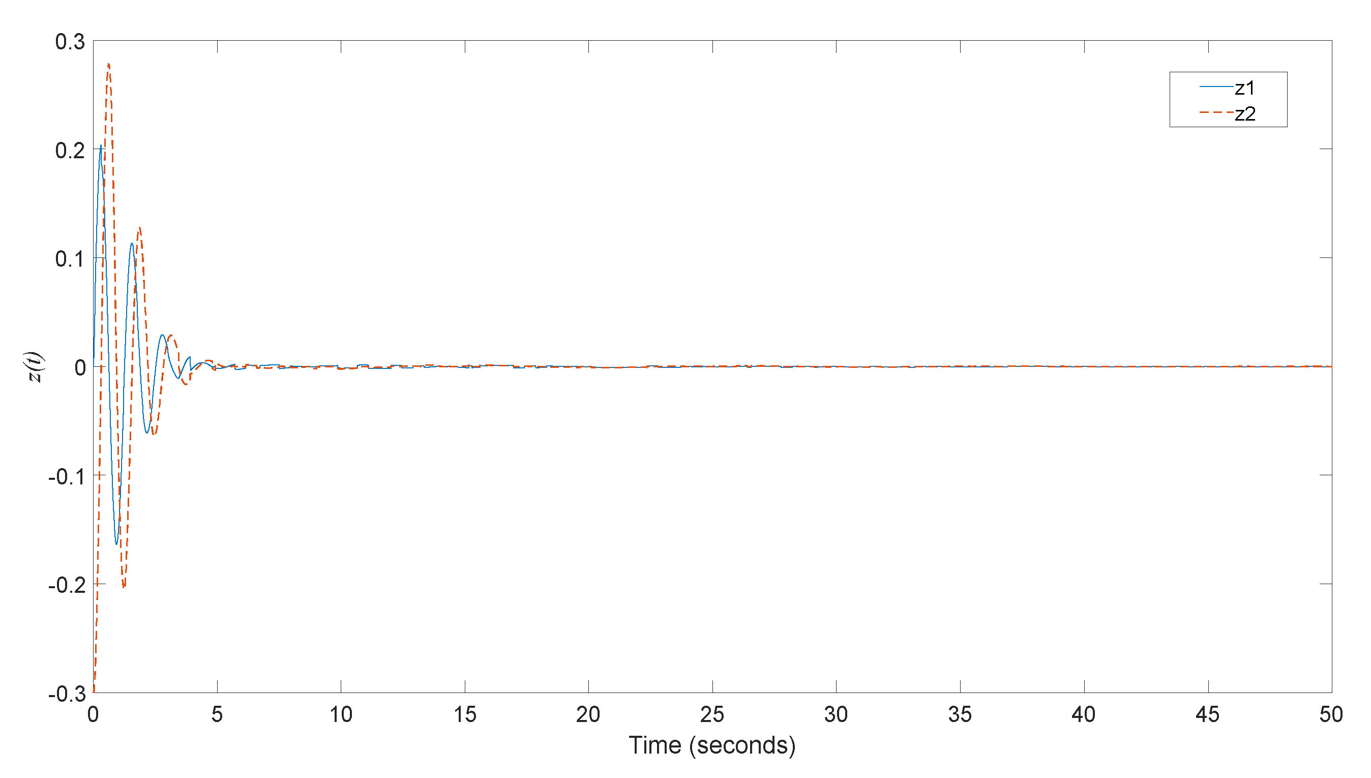
With no perturbations or disturbance,  φ ( t ) = [ 2 2 ] T ,  3.5 t 0 , and  h ( t ) = 3.25 0.25 s i n ( 0.1 t ) , the state trajectories of system (1) using the synchronous switching signal in (29) and sampling input in (30) are shown in Figure 1. Withdisturbance  w ( t ) = [ e 0.5 t sin ( 5 t ) e 0.5 t cos ( 5 t ) ]  depicted in Figure 2, the output  z ( t ) 2  with a zero initial state is shown in Figure 3. According to the simulation results, the variation in state response would be affected by feedback from the time-varying delay. Theproposed switching signal in (29) and sampling input in (30) are shown to be effective for stabilization and attenuation of disturbance in our considered system.

4. Conclusions

In this paper, synchronous switching of rule and sampling input was proposed to guarantee the H performance of switched delay systems with linear fractional perturbations. We developed a full-matrix formulation approach to show the main contribution of this paper. Some useful inequalities and Lyapunov–Krasovskii functionals were investigated to improve the conservativeness of the proposed results. Finally, we illustrated some numerical examples to show the use of our main results. Robust control with sampling input was developed in order to stabilize uncertain switching with interval time-varying delay and achieve H performance. Interval time-varying delay and sampling were investigated, instead of constant delay and pointwise sampling in [18]. It is interesting to note that fractional-order systems with time delay [28,29] and sampling input for uncertain systems with actuator saturation [30] will be challenging research topics in our future work. Synchronous switching of rule and input to reach mixed H 2 , H , and passive performances of uncertain fractional-order switched delay systems can be investigated in the future [25].

Author Contributions

Conceptualization, C.-H.L. and H.-C.C.; methodology, K.-W.Y. and H.-C.L.; software, H.-C.C.; validation, H.-C.C.; formal analysis, C.-H.L. and Y.-Y.H.; investigation, H.-C.C.; resources, K.-W.Y.; data curation, H.-C.C.; writing—original draft preparation, C.-H.L.; writing—review and editing, C.-H.L.; visualization, H.-C.C. and H.-C.L.; supervision, C.-H.L.; project administration, C.-H.L.; funding acquisition, C.-H.L. and Y.-Y.H. The authors declare that the study was realized in collaboration with the same responsibility. All authors have read and agreed to the published version of the manuscript.

Funding

The research reported here was supported by the Ministry of Science and Technology of Taiwan, under grant nos. MOST 110-2221-E-992-087 and MOST 111-2218-E-006-009 -MBK.

Institutional Review Board Statement

Not applicable.

Informed Consent Statement

Not applicable.

Data Availability Statement

Data are contained within the article.

Conflicts of Interest

The authors declare no conflict of interest.

Nomenclature

A T The transposition of a matrix A
A > 0 Matrix A is symmetric positive definite
A < 0 Matrix A is symmetric negative definite
A B For any two matrices A and B , the matrix B A is symmetric positive semi-definite
Sym ( S ) For any matrix S , Sym ( S ) is defined as the matrix S + S T
[ A B * C ] The sign * is defined as the matrix
I Identity matrix with appropriate dimensions
0Zero matrix with appropriate dimensions
0 i × j Zero matrix with i rows and j columns
Φ Empty set
A B Intersection of sets A and B
A B Union of sets A and B
Set of real numbers
E q , i [ 0 n × ( i 1 ) n I 0 n × ( q i ) n ] n × qn , i = 1 , 2 , , q , q = 2 , 3 , , 16
A \ B For any two sets A and B , the set A \ B is defined to be { x | x A and x B }
L 2 ( 0 , ) For a vector valued function w m , the set L 2 ( 0 , ) is defined to be { w m | 0 w T ( t ) w ( t ) dt < }
N _ For a natural number N , the set N _ is defined to be { 1 , 2 , , N }

References

  1. Gu, K.; Kharitonov, V.L.; Chen, J. Stability of Time-Delay Systems; Birkhauser: Boston, MA, USA, 2003. [Google Scholar]
  2. Hale, J.K.; Verduyn Lunel, S.M. Introduction to Functional Differential Equations; Springer-Verlag: New York, NY, USA, 1993. [Google Scholar]
  3. Kolmanovskii, V.B.; Myshkis, A. Introduction to the Theory and Applications of Functional Differential Equations; Kluwer Academic Publishs: Dordrecht, The Netherlands, 1999. [Google Scholar]
  4. Chiasson, J.; Loiseau, J.J. Applications of Time Delay Systems; Lecture Notes in Control and Information Sciences; Springer: Berlin/Heidelberg, Germany, 2007. [Google Scholar]
  5. Li, X.; Yurkovich, S. Sliding mode control of delayed systems with application to engine idle speed control. IEEE Trans. Control. Syst. Technol. 2001, 9, 802–810. [Google Scholar]
  6. Sipahi, R.; Vyhlídal, T.; Niculescu, S.I.; Pepe, P. Time Delay Systems: Methods, Applications and New Trends; Lecture Notes in Control and Information Sciences; Springer: Berlin/Heidelberg, Germany, 2012. [Google Scholar]
  7. Vimal Kumar, S.; Sakthivel, R.; Sathishkumar, M.; Marshal Anthoni, S. Finite time passive reliable filtering for fuzzy systems with missing measurements. ASME J. Dyn. Syst. Meas. Control. 2018, 140, 081009. [Google Scholar] [CrossRef]
  8. Wu, L.; Lam, H.K.; Zhao, Y.; Shu, Z. Time-delay systems and their applications in engineering 2014. Math. Probl. Eng. 2015, 2015, 246351. [Google Scholar] [CrossRef]
  9. Wang, C.; Wu, L.; Shen, J. Stability and L performance analysis of positive systems with bounded time-varying delays on time scales. Nonlinear Anal. Hybrid Syst. 2020, 36, 100868. [Google Scholar] [CrossRef]
  10. Zhang, D.; Yu, L. Exponential stability analysis for neutral switched systems with interval time-varying mixed delays and nonlinear perturbations. Nonlinear Anal. Hybrid Syst. 2012, 6, 775–786. [Google Scholar] [CrossRef]
  11. Mahmoud, M.S. Switched Time-Delay Systems; Springer: Boston, MA, USA, 2010. [Google Scholar]
  12. Sun, Z.; Ge, S.S. Stability Theory of Switched Dynamical Systems; Springer: London, UK, 2011. [Google Scholar]
  13. Sun, X.M.; Wang, W.; Liu, G.P.; Zhao, J. Stability analysis for linear switched systems with time-varying delay. IEEE Trans. Syst. Man Cybernet. B 2008, 38, 528–533. [Google Scholar]
  14. Sun, Y.G.; Wang, L.; Xie, G. Stability of switched systems with time-varying delays: Delay-dependent common Lyapunov functional approach. Proc. Amer. Control Conf. 2006, 5, 1544–1549. [Google Scholar]
  15. Liu, C.; Liu, X. Stability of switched systems with time-varying delays under state-dependent switching. Mathematics 2022, 10, 2722. [Google Scholar] [CrossRef]
  16. Phat, V.N.; Ratchagit, K. Stability and stabilization of switched linear discrete-time systems with interval time-varying delay. Nonlinear Anal. Hybrid Syst. 2011, 5, 605–612. [Google Scholar] [CrossRef]
  17. Zhang, L.; Shi, P.; Basin, M. Robust stability and stabilisation of uncertain switched linear discrete time-delay systems. IET Proc. Control Theory Appl. 2008, 2, 606–614. [Google Scholar] [CrossRef]
  18. Lien, C.H.; Hou, Y.Y.; Yu, K.W.; Chang, H.C. Aperiodic sampled-data robust H control of uncertain continuous switched time-delay systems. Int. J. Syst. Sci. 2020, 51, 2005–2024. [Google Scholar] [CrossRef]
  19. Li, B.; Zhao, X.; Liu, Y.; Zhao, X. Robust H control of fractional-order switched systems with order 0 < α <1 and uncertainty. Fractal Fract. 2022, 6, 164. [Google Scholar]
  20. Chen, G.; Xiang, G.; Karimi, H.R. Observer-based robust H control for switched stochastic systems with time-varying delay. Abstr. Appl. Anal. 2013, 2013, 320703. [Google Scholar] [CrossRef]
  21. Lam, H.K.; Leung, F.H.F. Sampled-data fuzzy controller for time-delay nonlinear system: LMI-based and fuzzy-model-based approaches. IEEE Trans. Syst. Man Cybern. Part B 2007, 37, 617–629. [Google Scholar] [CrossRef] [Green Version]
  22. Li, T.; Guo, L.; Sun, C. Robust stability for neural networks with time-varying delays and linear fractional uncertainties. Neurocomputing 2007, 71, 421–427. [Google Scholar] [CrossRef]
  23. Yang, J.; Luo, W.; Li, G.; Zhong, S. Reliable guaranteed cost control for uncertain fuzzy neutral systems. Nonlinear Anal. Hybrid Syst. 2010, 4, 644–658. [Google Scholar] [CrossRef]
  24. Zeng, H.B.; Teo, K.L.; He, Y. A new looped-functional for stability analysis of sampled-data systems. Automatica 2017, 82, 328–331. [Google Scholar] [CrossRef]
  25. Lien, C.H.; Chang, H.C.; Yu, K.W.; Lee, H.C.; Hou, Y.Y. Robust mixed performance control of uncertain T-S fuzzy systems with interval time-varying delay by sampled-data input. IEEE Access 2022, 10, 28109–28121. [Google Scholar] [CrossRef]
  26. Lee, W.I.; Lee, S.Y.; Park, P. Affine bessel-legendre inequality: Application to stability analysis for systems with time-varying delays. Automatica 2018, 93, 535–539. [Google Scholar] [CrossRef]
  27. Boyd, S.P.; Ghaoui, L.E.; Feron, E.; Balakrishnan, V. Linear Matrix Inequalities in System and Control Theory; SIAM: Philadelphia, PA, USA, 1994. [Google Scholar]
  28. Jia, J.; Huang, X.; Li, Y.; Cao, J.; Alsaedi, A. Global stabilization of fractional-order memristor-based neural networks with time delay. IEEE Trans. Neural Netw. Learn. Syst. 2020, 31, 997–1009. [Google Scholar] [CrossRef]
  29. Wang, Z.; Wang, X.; Xia, J.; Shen, H.; Meng, B. Adaptive sliding mode output tracking control based-FODOB for a class of uncertain fractional-order nonlinear time-delayed systems. Sci. China Technol. Sci. 2020, 63, 1854–1862. [Google Scholar] [CrossRef]
  30. Santra, S.; Joby, M.; Sathishkumar, M. LMI approach-based sampled-data control for uncertain systems with actuator saturation: Application to multi-machine power system. Nonlinear Dyn. 2022, 107, 967–982. [Google Scholar] [CrossRef]
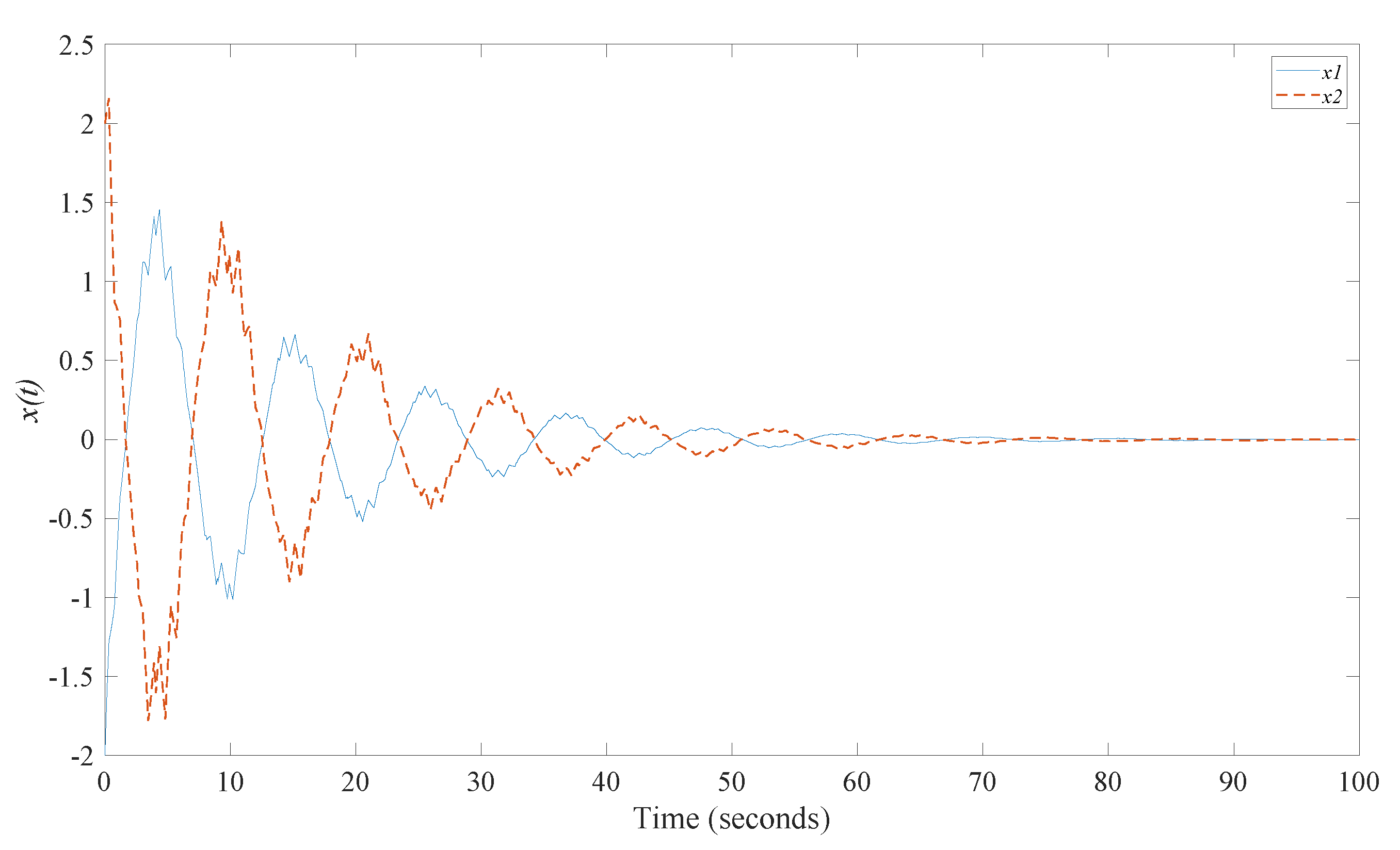
Figure 1. State trajectories of system (1) for the synchronous signal in (29) and sampling input in (30).
Fractalfract 06 00479 g001
Figure 2. Disturbance input.
Fractalfract 06 00479 g002
Figure 3. Output of system (1) for the synchronous signal in (29) and sampling input in (30).
Fractalfract 06 00479 g003
Table 1. Comparison of the obtained results with published ones.
Results Delay   h ( t ) Sampling PeriodDisturbance Attenuation
[18] h ( t ) = h = 0.2 constant delay τ = 0.2 γ = 0.7873
τ = 0.25 γ = 0.7918
[18] h ( t ) = h = 1 constant delay τ i = 0.2 ,   τ j = 0.3
for some values in
i and j
pointwise sampling
γ = 0.632
Results of Theorem 1 in this paper:
synchronous switching of rule and sampling input
1 h ( t ) 1.2 ,   h D unknown 0 < τ i 0.3 γ = 0.5177
Table 2. Comparison of the obtained results with published ones.
ResultsSampling PeriodDisturbance AttenuationApproach and Delay
[18] τ i = 0.03 ,   τ j = 0.05
for some values in i and j pointwise sampling
γ = 0 . 8355 Synchronous   switching   of   rule   and   sampling   input   with   constant   delay   h ( t ) = h = 3.4 .
γ = 1 . 0951 Arbitrary   switching   with   sampling   input   and   constant   delay   h ( t ) = h = 3.4 .
Results in Theorem 1 0 < τ i 0.1 γ = 0.3523 Using   only   switching   rule   with   3 h ( t ) 3.5
γ = 0 . 311 Synchronous switching of rule and sampling input with
3 h ( t ) 3.5 .
Results in Corollary 1 γ = 0 . 618 σ ( t )   is   arbitrary   and   captured   at   each   sampling   instant   with   3 h ( t ) 3.5 .
Publisher’s Note: MDPI stays neutral with regard to jurisdictional claims in published maps and institutional affiliations.