
Effects of Fly Ash Dosage on Shrinkage, Crack Resistance and Fractal Characteristics of Face Slab Concrete


Abstract
:1. Introduction
2. Materials and Methods
2.1. Materials
2.2. Mix Proportions of Face Slab Concrete
2.3. Test and Calculation Methods
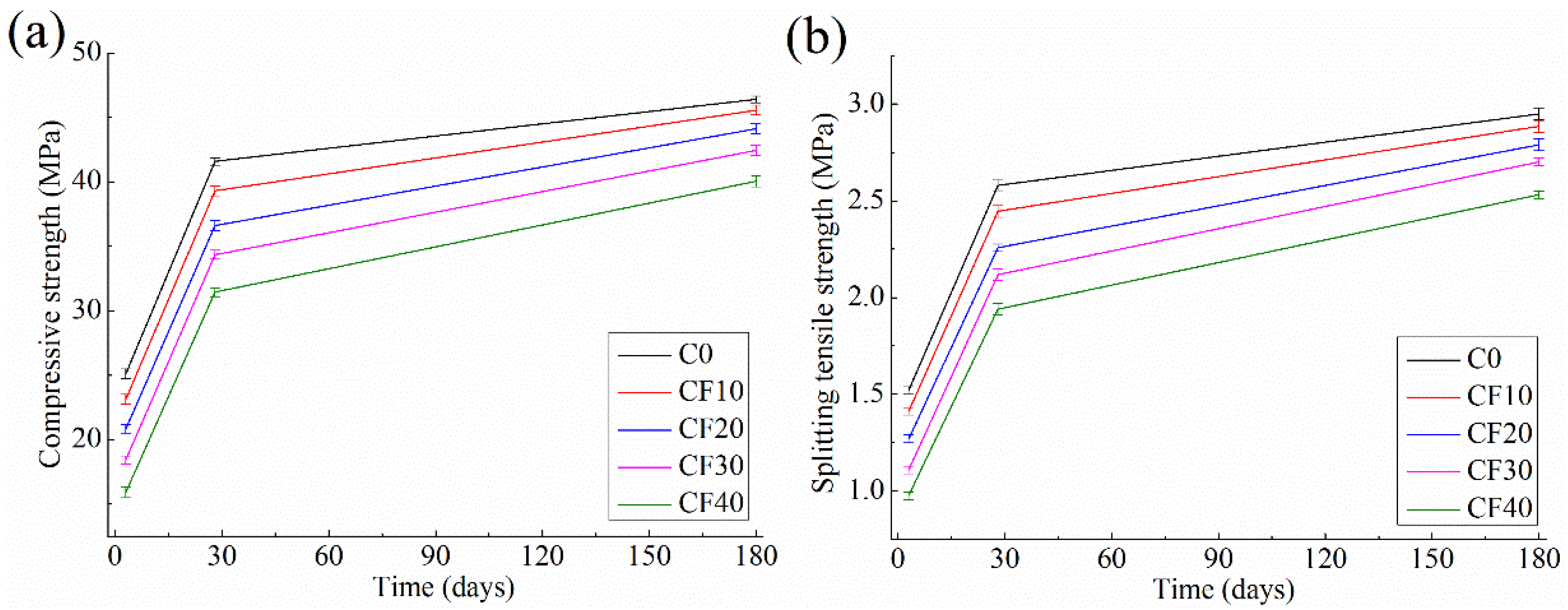
2.3.1. Compressive and Splitting Tensile Strength Test of Face Slab Concretes
2.3.2. Shrinkage Behavior Measurements
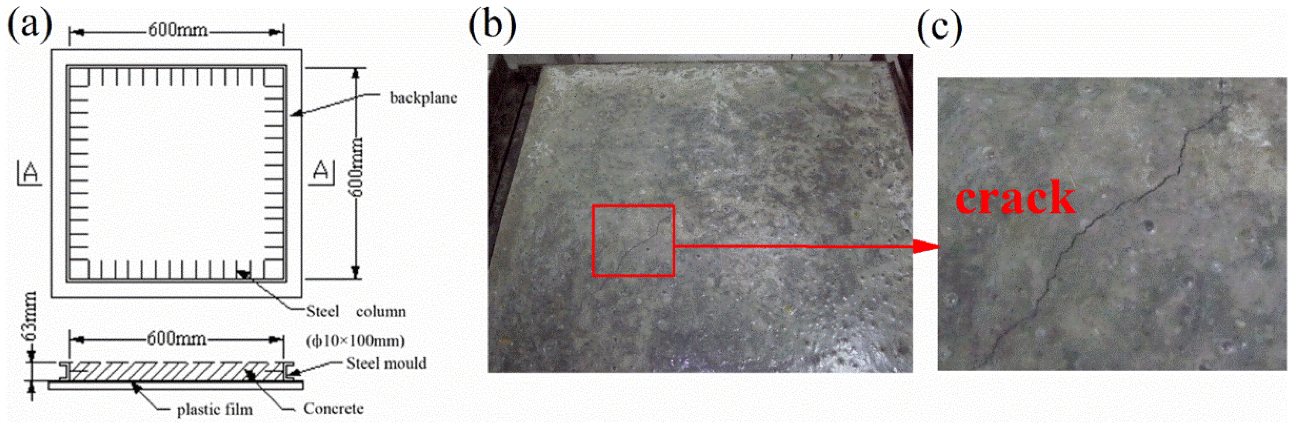
2.3.3. Cracking Resistance Test of Concrete
The Concrete Slab Test
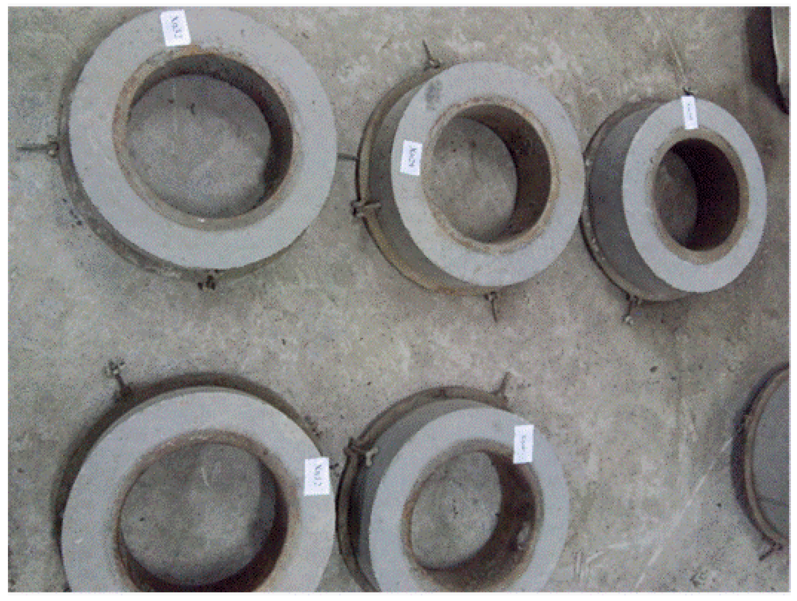
The Restrained Concrete Ring Test
2.3.4. Pore Structure Parameters by Mercury Intrusion Porosimeter (MIP)
2.3.5. Fractal Method
3. Results and Discussion
3.1. Compressive and Splitting Tensile Strength
3.2. Volume Deformation
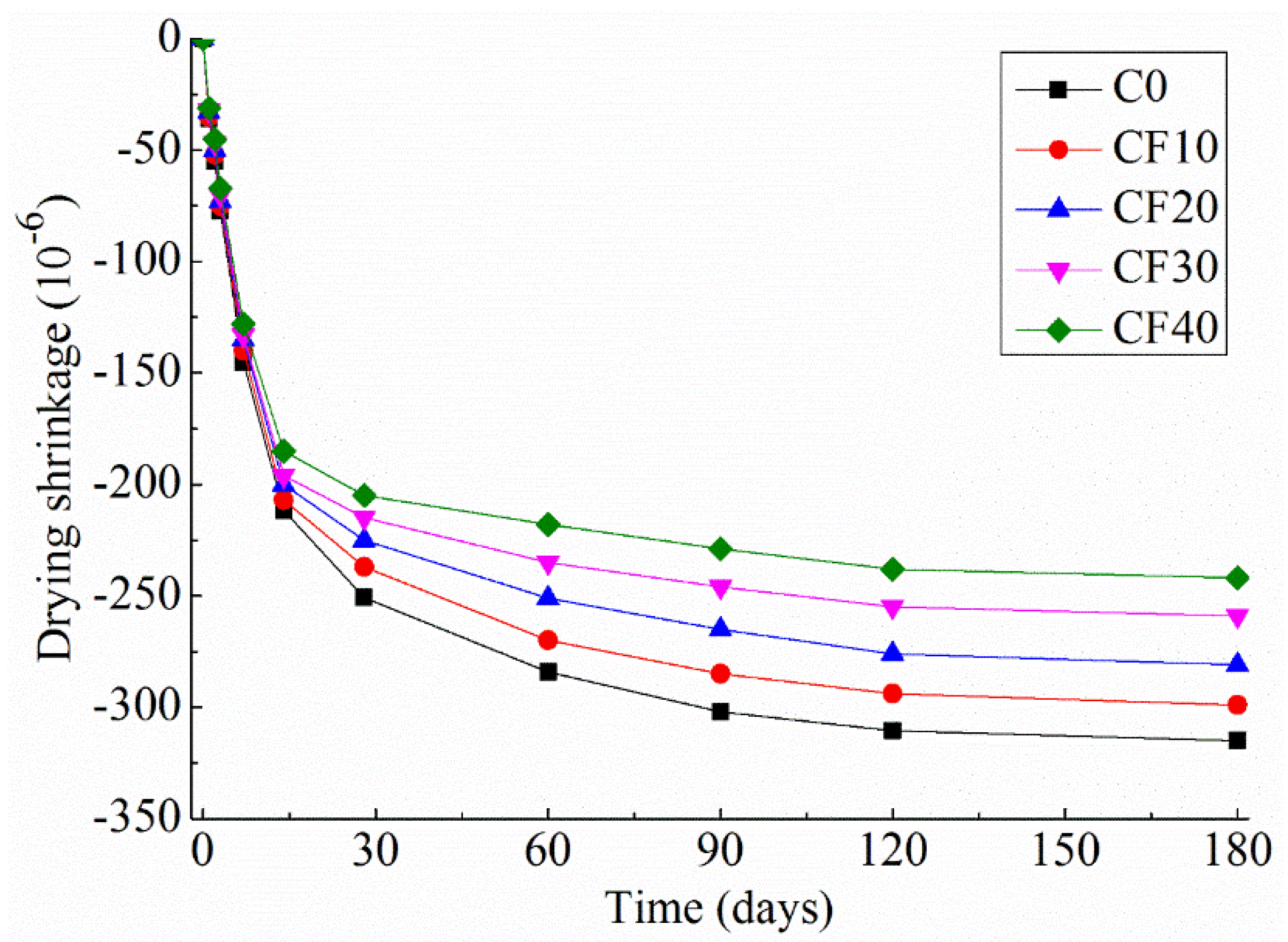
3.2.1. Drying Shrinkage
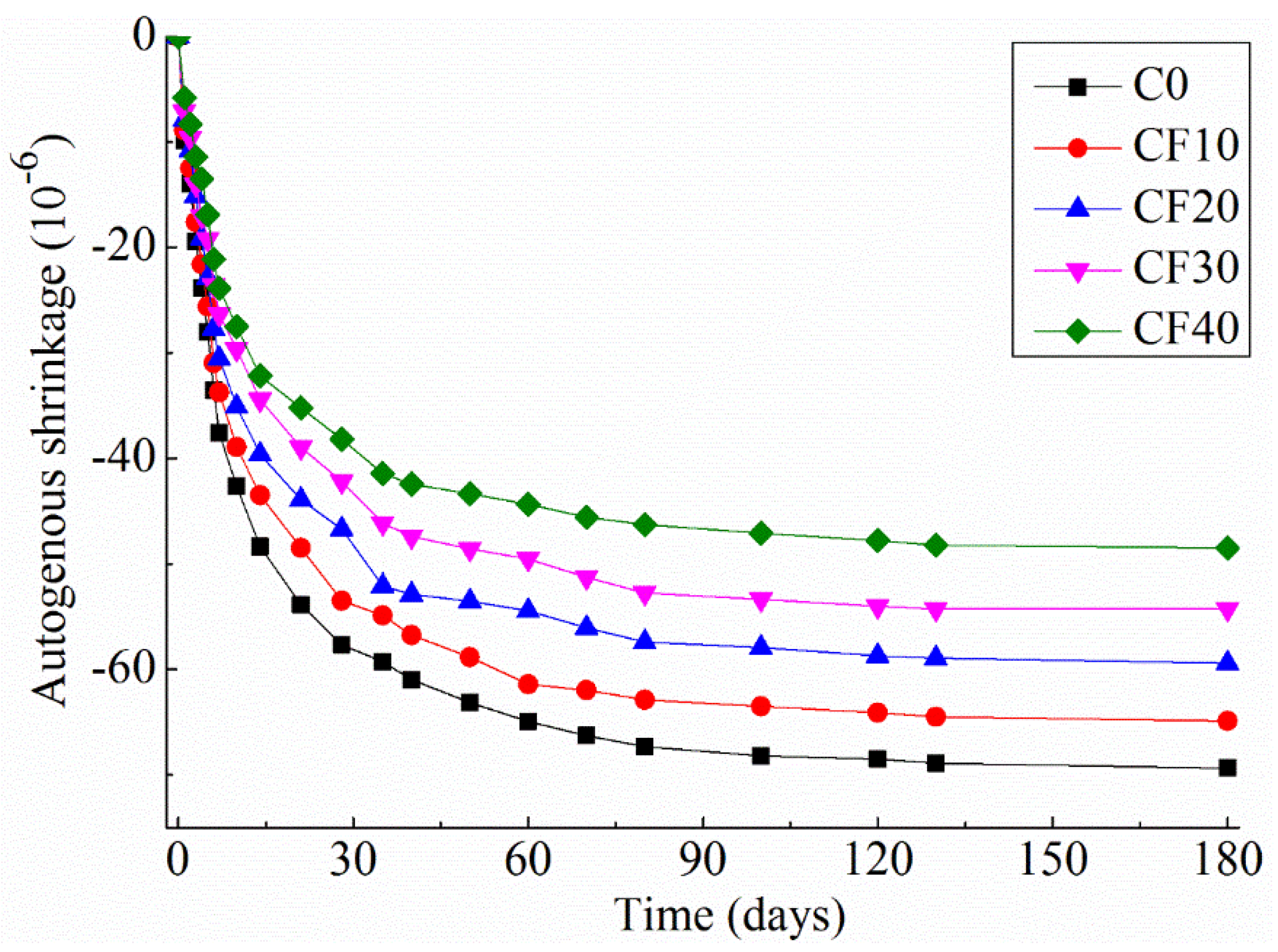
3.2.2. Autogenous Shrinkage
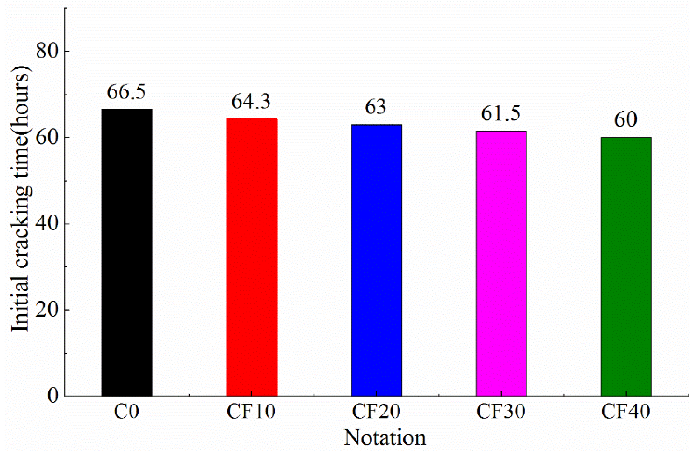
3.3. Cracking Resistance
3.3.1. The Concrete Slab Test Result
3.3.2. Restrained Concrete Ring Test Result
3.4. MIP Result
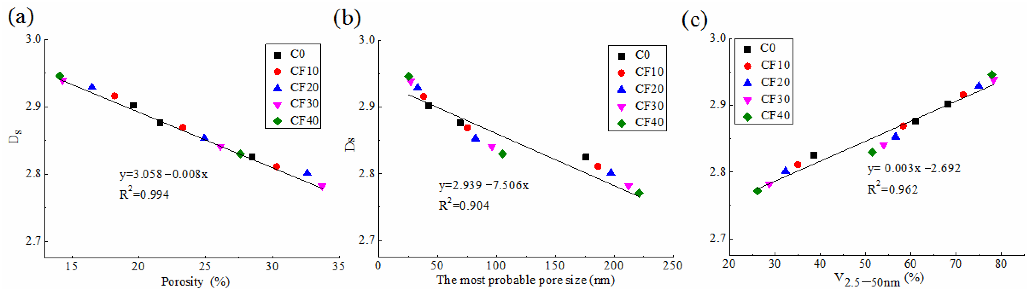
3.5. Fractal Characteristics of Face Slab Concretes
3.6. Pore Structural and Fractal Viewpoint of Shrinkage Behavior
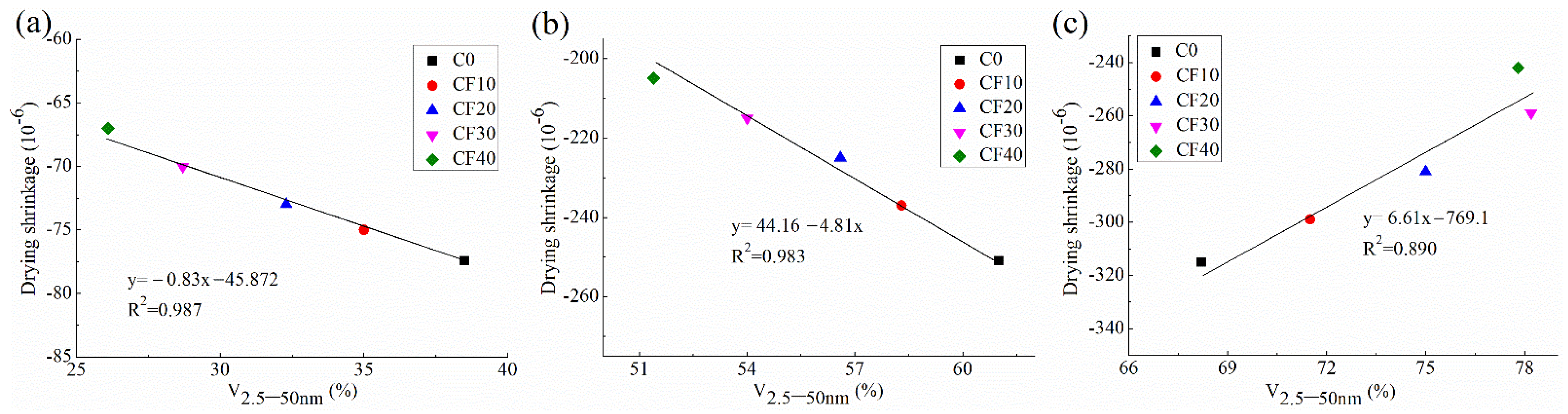
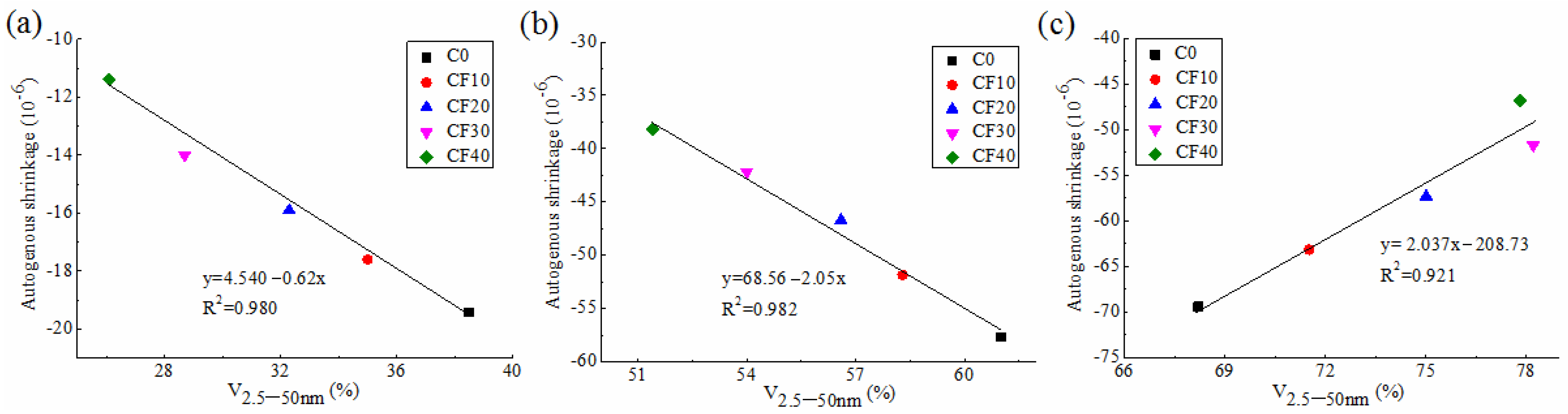
3.6.1. Correlation between Shrinkage and Pore Structure
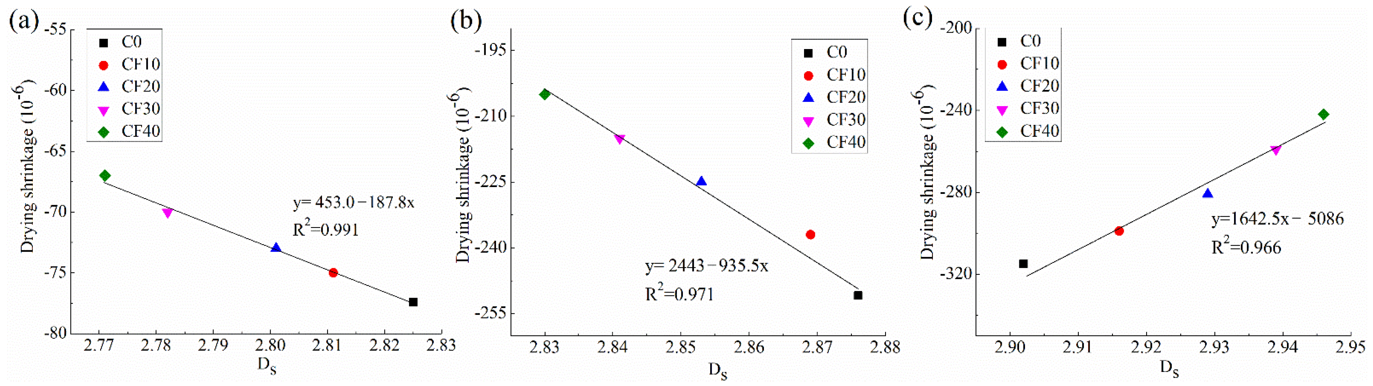
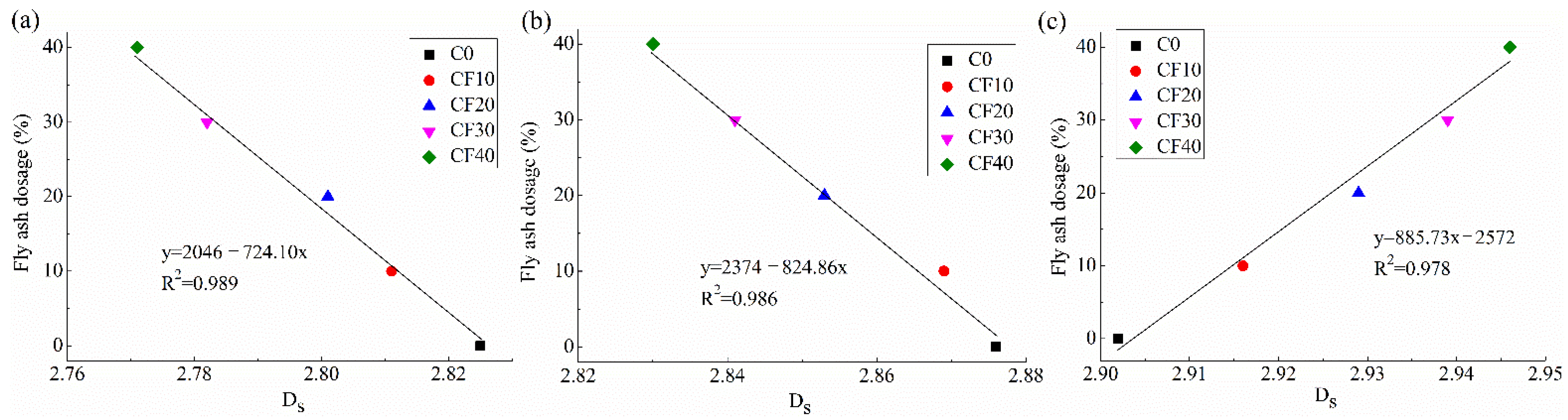
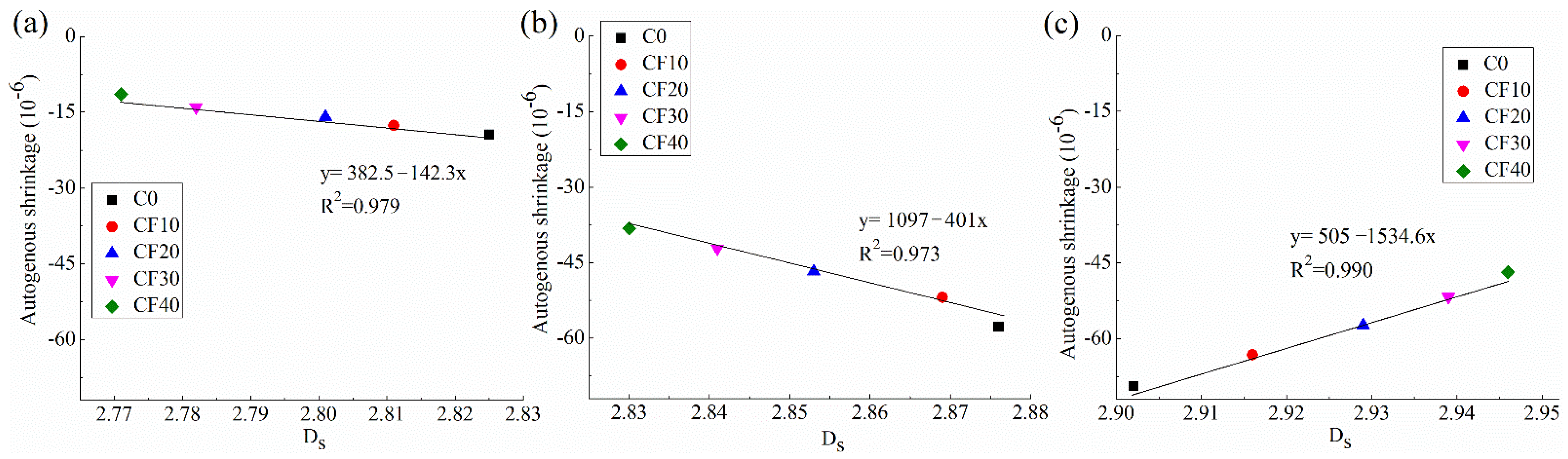
3.6.2. Correlation between Shrinkage and Ds
4. Conclusions
- (1)
- The incorporation of 10–40% fly ash could slightly reduce the drying shrinkage by about 2.2–13.5% before 14 days of hydration, and it could reduce the drying shrinkage at 180 days by about 5.1–23.2%. By contrast, the fly ash addition could largely reduce the autogenous shrinkage at early, middle and long-term ages.
- (2)
- Increasing fly ash dosage from 0 to 40% significantly improves the crack resistance of face slab concretes to plastic shrinkage. Nevertheless, the increase in fly ash dosage increases the drying-induced cracking risk under restrained conditions.
- (3)
- The pore structures of face slab concrete at 3 and 28 days become coarser with the increase in fly ash dosage up to 40%. At 180 days, the pore structures become more refined as the fly ash dosage increases to 30%; however, this refinement effect is not appreciable as the fly ash dosage increases from 30% to 40%.
- (4)
- The Ds of face slab concrete is strongly related with the concrete pore structures. The Ds of face slab concrete at a late age increased from 2.902 to 2.946 with increasing the fly ash dosage from 0 to 40%. The pore structure and Ds are closely correlated with the shrinkage of face slab concrete. The higher shrinkage of face slab concrete was accompanied by a higher fraction of small pores and Ds at 3 and 28 days, whereas the 180 day-shrinkage increased as the fraction of small pores and Ds declined.
- (5)
- A fly ash dosage around 30% is optimal for face slab concretes in terms of lowering shrinkage and refining the pore structures, without compromising much mechanical property. However, the face slab concretes with a large fly ash dosage should be well cured under restrained and evaporation conditions at an initial hydration age.
Author Contributions
Funding
Data Availability Statement
Acknowledgments
Conflicts of Interest
References
- Qu, Y.Q.; Zou, D.G.; Kong, X.J.; Liu, J.M.; Zhang, Y.; Yu, X. Seismic damage performance of the steel fiber reinforced face slab in the concrete-faced rockfill dam. Soil Dyn. Earthq. Eng. 2019, 119, 320–330. [Google Scholar] [CrossRef]
- Kong, X.J.; Zhang, Y.; Zou, D.G.; Yong, Q.; Xiang, Y.U. Seismic cracking analyses of two types of face slab for concrete-faced rockfill dams. Sci. China Technol. Sc. 2017, 60, 510–522. [Google Scholar] [CrossRef]
- Ma, H.Q.; Chi, F.D. Technical progress on researches for the safety of high concrete-faced rockfill dams. Engineering 2016, 2, 332–339. [Google Scholar] [CrossRef] [Green Version]
- Cen, W.J.; Wen, L.S.; Zhang, Z.Q.; Xiong, K. Numerical simulation of seismic damage and cracking of concrete slabs of high concrete face rockfill dams. Water Sci. Technol. 2016, 9, 205–211. [Google Scholar] [CrossRef] [Green Version]
- Wang, Z.J.; Liu, S.H.; Vallejo, L.; Wang, L.J. Numerical analysis of the causes of face slab cracks in Gongboxia rockfill dam. Eng. Geol. 2014, 181, 224–232. [Google Scholar] [CrossRef]
- Oskouei, A.V.; Nazari, R.; Khaneghahi, M.H. Laboratory and in situ investigation of the compressive strength of CFRD concrete. Constr. Build. Mater. 2020, 242, 118166. [Google Scholar] [CrossRef]
- Jia, J.S. A technical review of hydro-project development in China. Engineering 2016, 2, 302–312. [Google Scholar] [CrossRef] [Green Version]
- Yang, Z.Y.; Chao, L.; Wu, M.X. Leading-edge technologies in hydropower development in China. Glob. Energy Interconnect. 2019, 2, 244–253. [Google Scholar] [CrossRef]
- Woo, S.K.; Song, Y.C.; Won, J.P. Enhanced durability performance of face slab concrete in Concrete-Faced Rock-filled Dam using fly ash and PVA fibre. KSEC J. Civ. Eng. 2011, 15, 875–882. [Google Scholar] [CrossRef]
- Zhou, W.; Hua, J.; Chang, X.; Zhou, C. Settlement analysis of the Shuibuya concrete-face rockfill dam. Comput. Geotech. 2011, 38, 269–280. [Google Scholar] [CrossRef]
- Baak, S.H.; Cho, G.C.; Song, K.I. Stability analysis on the concrete slab of the highest concrete-faced rock-fill dam in South Korea. Geomech. Eng. 2017, 13, 881–892. [Google Scholar]
- Altoubat, S.; Talha Junaid, M.; Leblouba, M.; Badran, D. Effectiveness of fly ash on the restrained shrinkage cracking resistance of self-compacting concrete. Cem. Concr. Compos. 2017, 79, 9–20. [Google Scholar] [CrossRef]
- Wongkeo, W.; Thongsanitgarn, P.; Chaipanich, A. Compressive strength and drying shrinkage of fly ash-bottom ash-silica fume multi-blended cement mortars. Mater. Des. 2012, 36, 655–662. [Google Scholar] [CrossRef]
- Termkhajornkit, P.; Nawa, T.; Nakai, M.; Saito, T. Effect of fly ash on autogenous shrinkage. Cem. Concr. Res. 2005, 35, 473–482. [Google Scholar] [CrossRef]
- Kristiawan, S.A.; Aditya, M.T.M. Effect of high volume fly ash on shrinkage of self-compacting concrete. Procedia Eng. 2015, 125, 705–712. [Google Scholar] [CrossRef] [Green Version]
- Hu, X.; Shi, C.J.; Shi, Z.G.; Tong, B.H.; Wang, D.H. Early age shrinkage and heat of hydration of cement-fly ash-slag ternary blends. Constr. Build. Mater. 2017, 153, 857–865. [Google Scholar] [CrossRef]
- Bouchenafa, O.; Hamzaoui, R.; Bennabi, A.; Colin, J. PCA effect on structure of fly ashes and slag obtained by mechanosynthesis. Applications: Mechanical performance of substituted paste CEMI + 50% slag/or fly ashes. Constr. Build. Mater. 2019, 203, 120–133. [Google Scholar] [CrossRef]
- Wang, L.; He, Z.; Cai, X.H. Characterization of pozzolanic reaction and its effect on the C-S-H gel in fly ash-cement paste. J. Wuhan Univ. Technol. 2011, 26, 320–325. [Google Scholar] [CrossRef]
- Yang, B.B.; Liu, J.W.; Zhao, X.M.; Zheng, S. Evaporation and cracked soda soil improved by fly ash from recycled materials. Land Degrad. Dev. 2021, 32, 2823–2832. [Google Scholar] [CrossRef]
- Zhang, P.; Wang, K.X.; Wang, J.; Guo, J.J.; Ling, Y.F. Macroscopic and microscopic analyses on mechanical performance of metakaolin/fly ash based geopolymer mortar. J. Clean. Prod. 2021, 294, 126193. [Google Scholar] [CrossRef]
- Nath, P.; Sarker, P. Effect of fly ash on the durability properties of high strength concrete. Procedia Eng. 2011, 14, 1149–1156. [Google Scholar] [CrossRef] [Green Version]
- Hu, X.; Shi, Z.G.; Shi, C.J.; Wu, Z.M.; Tong, B.H.; Ou, Z.H.; de Schutter, G. Drying shrinkage and cracking resistance of concrete made with ternary cementitious components. Constr. Build. Mater. 2017, 149, 406–415. [Google Scholar] [CrossRef]
- Atis, C.D. Heat evolution of high-volume fly ash concrete. Cem. Concr. Res. 2002, 32, 751–756. [Google Scholar] [CrossRef]
- Wang, L.; Yang, H.Q.; Zhou, S.H.; Chen, E.; Tang, S.W. Mechanical properties, long-term hydration heat, shinkage behavior and crack resistance of dam concrete designed with low heat Portland (LHP) cement and fly ash. Constr. Build. Mater. 2018, 187, 1073–1091. [Google Scholar] [CrossRef]
- Yin, B.; Kang, T.; Kang, J.; Chen, Y.; Wu, L.; Du, M. Investigation of the hydration kinetics and microstructure formation mechanism of fresh fly ash cemented filling materials based on hydration heat and volume resistivity characteristics. Appl. Clay Sci. 2018, 166, 146–158. [Google Scholar] [CrossRef]
- DL/T 5016-2011; Design Code for Concrete Faced Rockfill Dams, China. China Electric Power Press: Beijing, China, 2011.
- Bin, L.; Wang, L.; Zhou, S.; Liu, S. Research on mechanical properties and crack resistance of concrete slab under compound addition of fly ash and PVA fiber. Yangtze River 2018, 49, 84–87. (In Chinese) [Google Scholar] [CrossRef]
- Yoon, Y.S.; Won, J.P.; Woo, S.K. Enhanced durability performance of fly ash concrete for concrete-faced rockfill dam application. Cem. Concr. Res. 2002, 32, 23–30. [Google Scholar] [CrossRef]
- Zarnaghi, V.N.; Ali, F.A.; Nourani, V.; Ma, H.Y. On the pore structures of lightweight self-compacting concrete containing silica fume. Constr. Build. Mater. 2018, 193, 557–564. [Google Scholar] [CrossRef]
- Zeng, Q.; Luo, M.Y.; Pang, X.Y.; Li, L.; Li, K.F. Surface fractal dimension: An indicator to characterize the microstructure of cement-based porous materials. Appl. Surf. Sci. 2013, 282, 302–307. [Google Scholar] [CrossRef]
- Jin, S.S.; Zhang, J.X.; Han, S. Fractal analysis of relation between strength and pore structure of hardened mortar. Constr. Build. Mater. 2017, 135, 1–7. [Google Scholar] [CrossRef]
- Yu, P.; Duan, Y.H.; Chen, E.; Tang, S.W.; Wang, X.R. Microstructure-based fractal models for heat and mass transport properties of cement paste. Int. J. Heat Mass Transf. 2018, 126, 432–447. [Google Scholar] [CrossRef]
- Lü, Q.; Qiu, Q.L.; Zheng, J.; Wang, J.Y.; Zeng, Q. Fractal dimension of concrete incorporating silica fume and its correlations to pore structure, strength and permeability. Constr. Build. Mater. 2019, 228, 116986. [Google Scholar] [CrossRef]
- Yang, B.B.; Li, D.D.; Yuan, S.C.; Jin, L.C. Role of biochar from corn straw in influencing crack propagation and evaporation in sodic soils. Catena 2021, 204, 105457. [Google Scholar] [CrossRef]
- Zhang, P.; Gao, Z.; Wang, J.; Wang, K. Numerical modeling of rebar-matrix bond behaviors of nano-SiO2 and PVA fiber reinforced geopolymer composites. Ceram. Int. 2021, 47, 11727–11737. [Google Scholar] [CrossRef]
- Zhang, P.; Wang, K.X.; Wang, J.; Guo, J.J.; Hu, S.W.; Ling, Y.F. Mechanical properties and prediction of fracture parameters of geopolymer/alkali-activated mortar modified with PVA fiber and nano-SiO2. Ceram. Int. 2020, 46, 20027–20037. [Google Scholar] [CrossRef]
- Jin, S.S.; Zhang, J.X.; Huang, B.S. Fractal analysis of effect of air void on freeze–thaw resistance of concrete. Constr. Build. Mater. 2013, 47, 126–130. [Google Scholar] [CrossRef]
- DL/T 5330-2015; Code for Mix Design of Hydraulic Concrete, China. China Electric Power Press: Beijing, China, 2015.
- DL/T 5150-2017; Test Code for Hydraulic Concrete, China. China Electric Power Press: Beijing, China, 2017.
- Banthia, N.; Gupta, R. Influence of polypropylene fiber geometry on plastic shrinkage cracking in concrete. Cem. Concr. Res. 2006, 36, 1263–1267. [Google Scholar] [CrossRef]
- Khan, I.; Castel, A.; Gilbert, R.I. Tensile creep and early-age concrete cracking due to restrained shrinkage. Constr. Build. Mater. 2017, 149, 705–715. [Google Scholar] [CrossRef]
- Al-Amoudi, O.S.B.; Maslehuddin, M.; Shameem, M.; Ibrahim, M. Shrinkage of plain and silica fume cement concrete under hot weather. Cem. Concr. Compos. 2007, 29, 690–699. [Google Scholar] [CrossRef]
- Rao, G.A. Long-term drying shrinkage of mortar-influence of silica fume and size of fine aggregate. Cem. Concr. Res. 2001, 31, 171–175. [Google Scholar] [CrossRef]
- CCES 01-2004; Design and Construction Guide for the Durability of Concrete Structures, China. China Civil Engineering Society Press: Beijing, China, 2004.
- Yousefieh, N.; Joshaghani, A.; Hajibandeh, E.; Shekarchi, M. Influence of fibers on drying shrinkage in restrained concrete. Constr. Build. Mater. 2017, 148, 833–845. [Google Scholar] [CrossRef]
- ASTM C1581/C1581M-16; Standard Test Method for Determining Age at Cracking and Induced Tensile Stress Characteristics of Mortar and Concrete under Restrained Shrinkage. ASTM International: West Conshohocken, PA, USA, 2016.
- Shen, D.J.; Kang, J.C.; Yi, X.J.; Zhou, L.K.; Shi, X. Effect of double hooked-end steel fiber on early-age cracking potential of high strength concrete in restrained ring specimens. Constr. Build. Mater. 2019, 223, 1095–1105. [Google Scholar] [CrossRef]
- Wang, L.; Yang, H.Q.; Dong, Y.; Chen, E.; Tang, S.W. Environmental evaluation, hydration, pore structure, volume deformation and abrasion resistance of low heat Portland (LHP) cement-based materials. J. Clean. Prod. 2018, 203, 540–558. [Google Scholar] [CrossRef]
- Yang, B.; Liu, Y. Application of fractals to evaluate fractures of rock due to mining. Fractal Fract. 2022, 6, 96. [Google Scholar] [CrossRef]
- Zhang, B.Q.; Li, S.F. Determination of the surface fractal dimension for porous media by mercury porosimetry. Ind. Eng. Chem. Res. 1995, 34, 1383–1386. [Google Scholar] [CrossRef]
- Zhang, B.Q.; Liu, W.; Liu, X. Scale-dependent nature of the surface fractal dimension for bi- and multi-disperse porous solids by mercury porosimetry. Appl. Surf. Sci. 2006, 253, 1349–1355. [Google Scholar] [CrossRef]
- Bouzoubaâ, N.; Zhang, M.H.; Malhotra, V.M. Mechanical properties and durability of concrete made with high-volume fly ash blended cements using a coarse fly ash. Cem. Concr. Res. 2001, 31, 1393–1402. [Google Scholar] [CrossRef]
- De Matos, P.R.; Foiato, M.; Prudencio, L.R., Jr. Studies of the physical properties of hardened Portland cement paste—Part 8. The freezing of water in hardened Portland cement paste. Constr. Build. Mater. 2019, 203, 282–293. [Google Scholar]
- Termkhajornkit, P.; Nawa, T.; Kurumisawa, K. Effect of water curing conditions on the hydration degree and compressive strengths of fly ash–cement paste. Cem. Concr. Compos. 2006, 28, 781–789. [Google Scholar] [CrossRef]
- Jiang, D.B.; Li, X.G.; Lv, Y.; Zhou, M.K.; Li, C.J. Utilization of limestone powder and fly ash in blended cement: Rheology, strength and hydration characteristics. Constr. Build. Mater. 2020, 232, 117228. [Google Scholar] [CrossRef]
- Poon, C.S.; Lam, L.; Wong, Y.L. A study on high strength concrete prepared with large volumes of low calcium fly ash. Cem. Concr. Res. 2000, 30, 447–455. [Google Scholar] [CrossRef]
- Sakai, E.; Miyahara, S.; Ohsawa, S.; Lee, S.H.; Daimon, M. Hydration of fly ash cement. Cem. Concr. Res. 2005, 35, 1135–1140. [Google Scholar] [CrossRef]
- Oner, A.; Akyuz, S.; Yildiz, R. An experimental study on strength development of concrete containing fly ash and optimum usage of fly ash in concrete. Cem. Concr. Res. 2005, 35, 1165–1171. [Google Scholar] [CrossRef]
- Yang, J.; Huang, J.X.; He, X.Y.; Su, Y.; Oh, S.K. Shrinkage properties and microstructure of high volume ultrafine phosphorous slag blended cement mortars with superabsorbent polymer. J. Build. Eng. 2020, 52, 101121. [Google Scholar] [CrossRef]
- Deboodt, T.; Fu, T.; Ideker, J.H. Evaluation of FLWA and SRAs on autogenous deformation and long-term drying shrinkage of high performance concrete. Constr. Build. Mater. 2016, 119, 53–60. [Google Scholar] [CrossRef]
- Haneef, T.K.; Kumari, K.; Mukhopadhyay, C.K.; Venkatachalapathy; Rao, B.P.; Jayakumar, T. Influence of fly ash and curing on cracking behavior of concrete by acoustic emission technique. Constr. Build. Mater. 2013, 44, 342–350. [Google Scholar] [CrossRef]
- Gökçe, H.S.; Hatungimana, D.; Ramyar, K. Effect of fly ash and silica fume on hardened properties of foam concrete. Constr. Build. Mater. 2019, 194, 1–11. [Google Scholar] [CrossRef]
- Ma, Y.; Ye, G. The shrinkage of alkali activated fly ash. Cem. Concr. Res. 2015, 68, 75–82. [Google Scholar] [CrossRef]
- Yang, R.; Yu, R.; Shui, Z.H.; Gao, X. Low carbon design of an ultra-high performance concrete (UHPC) incorporating phosphorous slag. J. Clean. Prod. 2019, 240, 118157. [Google Scholar] [CrossRef]
- Moghaddam, F.; Sirivivatnanon, V.; Vessalas, K. The effect of fly ash fineness on heat of hydration, microstructure, flow and compressive strength of blended cement pastes. Case Stud. Constr. Mater. 2019, 10, e00218. [Google Scholar] [CrossRef]
- Mindess, S.; Young, J.F.; Darwin, D. Concrete; Prentice-Hall: Murray Hill, NJ, USA, 2003. [Google Scholar]
- Zhang, Y.M.; Sun, W.; Yan, H.D. Hydration of high-volume fly ash cement pastes. Cem. Concr. Compos. 2000, 22, 445–452. [Google Scholar] [CrossRef]
- Wang, L.; Dong, Y.; Zhou, S.H.; Chen, E.; Tang, S.W. Energy saving benefit, mechanical performance, volume stabilities, hydration properties and products of low heat cement-based materials. Energy Build. 2018, 170, 157–169. [Google Scholar] [CrossRef]
- Liu, P.; Cui, S.; Li, Z.; Xu, X.; Guo, C. Influence of surrounding rock temperature on mechanical property and pore structure of concrete for shotcrete use in a hot-dry environment of high-temperature geothermal tunnel. Constr. Build. Mater. 2019, 207, 329–337. [Google Scholar] [CrossRef]
- Xie, H.; Ni, G.; Li, S. The influence of surfactant on pore fractal characteristics of composite acidized coal. Fuel 2019, 253, 741–753. [Google Scholar] [CrossRef]
- Zeng, Q.; Li, K.F.; Teddy, F.C.; Patrick, D.L. Surface fractal analysis of pore structure of high-volume fly-ash cement pastes. Appl. Surf. Sci. 2010, 257, 762–768. [Google Scholar] [CrossRef]
- Li, Y.; Bao, J.; Guo, Y. The relationship between autogenous shrinkage and pore structure of cement paste with mineral admixtures. Constr. Build. Mater. 2010, 24, 1855–1860. [Google Scholar] [CrossRef]
- Zhang, W.; Ha, Y.; Na, S.H. Drying shrinkage and microstructure characteristics of mortar incorporating ground granulated blast furnace slag and shrinkage reducing admixture. Constr. Build. Mater. 2015, 93, 267–277. [Google Scholar] [CrossRef]
- Yuan, B.; Li, Z.; Zhao, Z.; Ni, H.; Su, Z. Experimental study of displacement field of layered soils surrounding laterally loaded pile based on Transparent Soil. J. Soils Sediments 2021, 21, 3072–3083. [Google Scholar] [CrossRef]
- Yuan, B.; Li, Z.; Chen, Y.; Ni, H.; Zhao, Z.; Chen, W. Mechanical and microstructural properties of recycling granite residual soil reinforced with glass fiber and liquid-modified polyvinyl alcohol polymer. Chemosphere 2021, 268, 131652. [Google Scholar] [CrossRef]
- Yuan, B.; Sun, M.; Wang, Y.; Zhai, L.; Luo, Q.; Zhang, X. Full 3D displacement measuring system for 3D displacement field of soil around a laterally loaded pile in transparent soil. Int. J. Geomech. 2019, 19, 04019028. [Google Scholar] [CrossRef]


| Oxides | Oxide Composition (wt. %) | |
|---|---|---|
| CEM I PC | Fly Ash | |
| CaO | 62.72 | 2.94 |
| SiO2 | 20.32 | 54.54 |
| Fe2O3 | 4.46 | 10.18 |
| Al2O3 | 4.42 | 24.78 |
| MgO | 3.92 | 2.94 |
| SO3 | 2.37 | 0.37 |
| R2O * | 0.41 | 1.04 |
| Loss on ignition (%) | 1.04 | 2.18 |
| Physical Properties | ||
| Specific gravity | 3.22 | 2.32 |
| Specific surface area by Blaine method (m2/kg) | 332 | 386 |
| Fineness (% retain in 45 µm) | 8.4 | 6.8 |
| Strength activity index | - | 78 |
| Designations | W/B Ratio | Fly Ash Dosage (wt.%) | Mix Proportions (kg/m3) | Slump (mm) | |||||
|---|---|---|---|---|---|---|---|---|---|
| Water | Cement | Fly Ash | Sand | Coarse Aggregate | Super Plasticizer | ||||
| C0 | 0.4 | 0 | 122 | 305 | 0 | 630 | 1339 | 1.8 | 65 |
| CF10 | 0.4 | 10 | 122 | 293 | 12 | 631 | 1340 | 2.4 | 55 |
| CF20 | 0.4 | 20 | 122 | 281 | 24 | 631 | 1341 | 2.7 | 51 |
| CF30 | 0.4 | 30 | 122 | 293 | 12 | 631 | 1340 | 2.1 | 62 |
| CF40 | 0.4 | 40 | 122 | 281 | 24 | 631 | 1340 | 2.4 | 57 |
| Notation | Cracking Time (min) | αc (mm2) | Crack Resistance Level | ||
|---|---|---|---|---|---|
| C0 | 330 | 43.6 | 12 | 523.2 | V |
| CF10 | 410 | 31.6 | 7 | 221.2 | IV |
| CF20 | 480 | 15.6 | 6 | 93.6 | III |
| CF30 | 505 | 8.6 | 2 | 17.2 | I |
| CF40 | 540 | 8.4 | 3 | 25.2 | I |
| Notation | Hydration Time (Day) | The Most Probable Pore Size (nm) | Porosity (%) | Pore Size Distribution | ||
|---|---|---|---|---|---|---|
| <10 nm (%) | 10–50 nm (%) | 50 nm–10 μm (%) | ||||
| C0 | 3 | 176 | 28.5 | 7.9 | 30.6 | 61.2 |
| 28 | 69 | 21.6 | 14.3 | 46.7 | 38.9 | |
| 180 | 42 | 19.6 | 18.6 | 49.6 | 31.6 | |
| CF10 | 3 | 186 | 30.3 | 7.2 | 27.8 | 64.9 |
| 28 | 75 | 23.3 | 13.2 | 45.1 | 41.3 | |
| 180 | 38 | 18.2 | 20.3 | 51.2 | 28.3 | |
| CF20 | 3 | 197 | 32.6 | 6.7 | 25.6 | 67.5 |
| 28 | 82 | 24.9 | 13 | 43.6 | 43.2 | |
| 180 | 33 | 16.5 | 22.5 | 52.5 | 24.8 | |
| CF30 | 3 | 212 | 33.7 | 5.6 | 23.1 | 70.6 |
| 28 | 96 | 26.1 | 12.1 | 41.9 | 45.6 | |
| 180 | 27 | 14.3 | 24.3 | 53.9 | 21.6 | |
| CF40 | 3 | 221 | 35.9 | 4.7 | 21.4 | 73.7 |
| 28 | 105 | 27.6 | 10.6 | 40.8 | 48.3 | |
| 180 | 25 | 14.1 | 24.2 | 53.6 | 22.1 | |
| Notation | Hydration Time (Day) | Ds | R2 |
|---|---|---|---|
| C0 | 3 | 2.825 | 0.956 |
| 28 | 2.876 | 0.978 | |
| 180 | 2.902 | 0.986 | |
| CF10 | 3 | 2.811 | 0.947 |
| 28 | 2.869 | 0.967 | |
| 180 | 2.916 | 0.956 | |
| CF20 | 3 | 2.801 | 0.969 |
| 28 | 2.853 | 0.981 | |
| 180 | 2.929 | 0.978 | |
| CF30 | 3 | 2.782 | 0.947 |
| 28 | 2.841 | 0.989 | |
| 180 | 2.939 | 0.988 | |
| CF40 | 3 | 2.771 | 0.978 |
| 28 | 2.830 | 0.975 | |
| 180 | 2.946 | 0.969 |
| Notation | Hydration Time (Days) | V2.5–50nm (%) |
|---|---|---|
| C0 | 3 | 38.5 |
| 28 | 61.0 | |
| 180 | 68.2 | |
| CF10 | 3 | 35.0 |
| 28 | 58.3 | |
| 180 | 71.5 | |
| CF20 | 3 | 32.3 |
| 28 | 56.6 | |
| 180 | 75.0 | |
| CF30 | 3 | 28.7 |
| 28 | 54.0 | |
| 180 | 78.2 | |
| CF40 | 3 | 26.1 |
| 28 | 51.4 | |
| 180 | 77.8 |
Publisher’s Note: MDPI stays neutral with regard to jurisdictional claims in published maps and institutional affiliations. |
© 2022 by the authors. Licensee MDPI, Basel, Switzerland. This article is an open access article distributed under the terms and conditions of the Creative Commons Attribution (CC BY) license (https://creativecommons.org/licenses/by/4.0/).
Share and Cite
Wang, L.; Yu, Z.; Liu, B.; Zhao, F.; Tang, S.; Jin, M. Effects of Fly Ash Dosage on Shrinkage, Crack Resistance and Fractal Characteristics of Face Slab Concrete. Fractal Fract. 2022, 6, 335. https://doi.org/10.3390/fractalfract6060335
Wang L, Yu Z, Liu B, Zhao F, Tang S, Jin M. Effects of Fly Ash Dosage on Shrinkage, Crack Resistance and Fractal Characteristics of Face Slab Concrete. Fractal and Fractional. 2022; 6(6):335. https://doi.org/10.3390/fractalfract6060335
Chicago/Turabian StyleWang, Lei, Zhiqiang Yu, Bo Liu, Feng Zhao, Shengwen Tang, and Minmin Jin. 2022. "Effects of Fly Ash Dosage on Shrinkage, Crack Resistance and Fractal Characteristics of Face Slab Concrete" Fractal and Fractional 6, no. 6: 335. https://doi.org/10.3390/fractalfract6060335
APA StyleWang, L., Yu, Z., Liu, B., Zhao, F., Tang, S., & Jin, M. (2022). Effects of Fly Ash Dosage on Shrinkage, Crack Resistance and Fractal Characteristics of Face Slab Concrete. Fractal and Fractional, 6(6), 335. https://doi.org/10.3390/fractalfract6060335