Article

A Variable-Order Fuzzy Logic Controller Design Method for an Unmanned Underwater Vehicle Based on NSGA-II

1
School of Marine Science and Technology, Northwestern Polytechnical University, Xi’an 710072, China
2
Research & Development Institute, Northwestern Polytechnical University, Shenzhen 518057, China
*
Author to whom correspondence should be addressed.
Fractal Fract. 2022, 6(10), 577; https://doi.org/10.3390/fractalfract6100577
Submission received: 31 July 2022 / Revised: 3 September 2022 / Accepted: 12 September 2022 / Published: 10 October 2022
(This article belongs to the Section Numerical and Computational Methods)

Abstract

:
UUV depth control requires the controlled system to have good transient response and robustness under the premise of ensuring real-time performance. The flexibility of fractional-order control provides an idea to solve this problem. This paper proposes a controller design method for UUV depth control (VD-SIFLC) based on fractional calculus, fuzzy control, dynamic parameters and a fast non-dominated sorting genetic algorithm (NSGA-II). First, the overall structure of the controller, the UUV model and the model of external disturbances are presented. Then, the design methods of control input, order selector, membership function and scale factor selector are given, respectively. Then, the necessary conditions, such as optimization objectives and optimization parameters in the optimization algorithm, are analyzed. Finally, the effectiveness of the proposed control scheme is verified by comparative experiments with the SIFLC. Simulation results show that the controlled system with the VD-FIFLC could achieve better robustness and dynamic and steady-state performance. Moreover, according to the actual task requirements, the appropriate parameters can be selected by the user from the pareto solution set, which is suitable to be used in the actual applications.

1. Introduction

Unmanned underwater vehicles (UUVs) have a broad range of practical applications. In the military aspect, this concept is generally applied for underwater warning, reconnaissance, tracking and covert attack. In the civilian application, it can be used for tasks such as hydrographic surveys, oceanographic research and water quality monitoring. As a maritime force multiplier, a UUV not only has extensive and important military applications, but also contributes an indispensable and important force to the peaceful development of the oceans by mankind. In recent years, the applications of UUVs have been widely explored, and now it has become the forefront of military marine technology in developed countries.
The UUV depth control technology is one of the most important parts of UUV control. For example, in the process of underwater docking of UUVs, both UUVs need to maintain a stable attitude at a given depth [1,2]. This puts forward higher requirements for the dynamic and steady-state performance of UUV depth control. The UUV motion control has the following characteristics. First, UUVs generally work in complex marine environments with complex and changeable external disturbances, so they should have strong robustness. Then, the UUV model is quite complex, which makes the controller design more difficult. Finally, UUVs are not always equipped with a high-performance processor, which requires the controller to have better real-time performance.
In the related studies of UUV motion control, the fuzzy control and variable order control methods have been widely used. The fuzzy control does not depend on the precise mathematical model of the controlled object and has strong robustness and fault tolerance. The variable-order control fills the vacancy of the integer order and can use the characteristics of different fractional orders to provide more possibilities for control. These characteristics make these two methods satisfy the requirements of UUV motion control.
The fuzzy control is widely used in UUV motion control. Inspired by the definition of distance, Ishaque et al. combined the error and its derivative as the control input and adopted a simplified rule table [3]. Aras et al. designed a fuzzy logic controller for UUV angle control. Aiming at the problem that membership function is mostly designed by empirical method and there is no unified standard, an optimization algorithm of membership function is proposed in [4]. Pham et al. introduced additional parameters in the process of the membership function optimization algorithm to bring the optimized controller more in line with the requirements of the UUV control system [5]. Tuan proposed a fuzzy controller for UUV depth control and developed related test software based on the Kalman filter and a fuzzy controller [6].
The variable-order control has also been used in UUV control in recent years. Han et al. proposed a dual-loop variable-order controller (DLFISMC) and applied the trajectory tracking control of UUV-mounted robotic arms [7]. Liu et al. proposed the intuition-fuzzy game into the UUV maneuver decision-making model and used the fractional-order PSO to optimize the strategy [8]. The authors also designed a fractional-order PID controller for UUV motion control [9]. Konar et al. designed a variable-order PID controller (FO-PID) and used the reaching law of fractional order [10]. Jia et al. combined the RBF neural network with the adaptive controller of fractional-order sliding mode control to solve the attitude stability problem in the process of UUV underwater docking [11]. Liu et al. proposed a fractional order PI controller for the motion control of UUV [12,13]. Xue et al. developed the FOTF toolbox and developed related functions and models [14]. Wan et al. adopted a cloud model-based genetic algorithm to tune the parameters of the fractional-order PID controller and used it for UUV motion control [15]. Zhang et al. studied the non-equivalent fractional-order delay system and general kind non-commensurate elementary fractional-order system and then gave a series of stability theorems [16,17].
In this paper, a variable-order fuzzy logic controller design method for an unmanned underwater vehicle based on NSGA-II is proposed. The main contributions are illustrated as follows:
  • The design method of the proposed controller is given with the ‘fractional distance’ as the input and the simplified fuzzy logic controller as the output.
  • The fractional order selection method is presented. According to the given depth, the real-time depth of the vehicle and the PWM wave, the corresponding controller order can be obtained.
  • The scale factor selector is given. According to the given depth and the real-time depth of the vehicle, the corresponding scale factor can be obtained.
  • The controller parameters are optimized by the non-dominated multi-objective genetic algorithm (NSGA-Ⅱ), and the Pareto optimal solution set is achieved.
  • The effectiveness of the proposed scheme is verified by comparing the dynamic and steady-state control performance of the VD-SIFLC and the SIFLC.

2. Control System Structure

The workflow of the control system includes the following processes as shown in Figure 1. The parameters involved in the control system are shown in Table 1. First, according to the needs of the task, the user selects the parameters that meet the needs from the Pareto solution set and gives the reference signal of the depth changing with time. Then, the controller obtains the control output according to the reference signal and controls the UUV model [18,19]. At the same time, the external disturbances are also applied to the UUV model [20,21]. Finally, the attitude information of the UUV is obtained through the sensor.

2.1. UUV Depth Controller

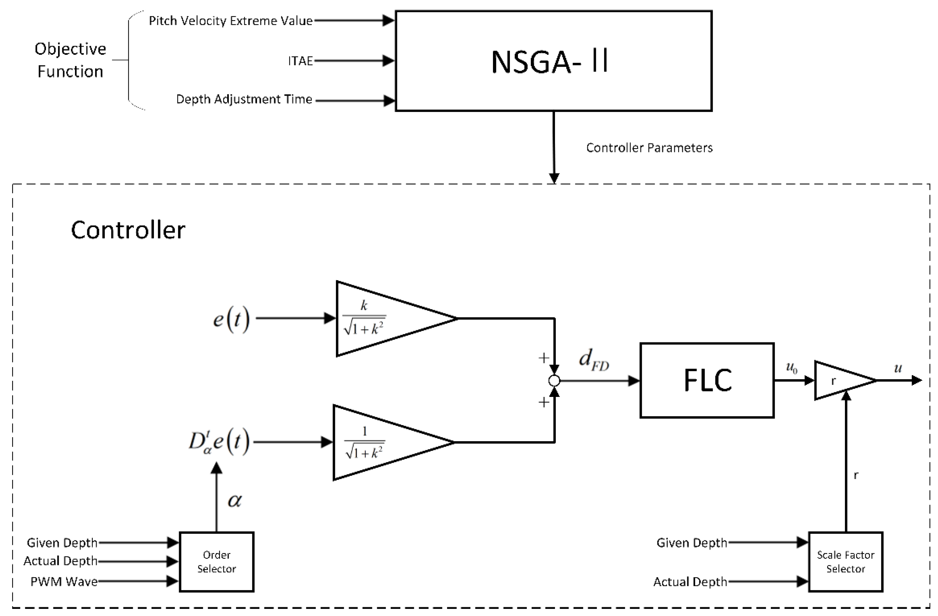
The controller mainly includes two parts, namely the proposed controller and the controller parameter optimization part. The controller consists of fractional order fuzzy logic controller, order selector and scale factor selector. Part of the controller parameters are obtained by the NSGA-II algorithm, and the optimization objectives include the extreme value of the pitch angular velocity, the ITAE index and adjustment time of the depth. The block diagram of the entire control system is shown in Figure 2.

2.1.1. Fractional-Order Fuzzy Logic Controller

There are three key points in the controller design, namely, the definition of fractional distance, the construction of one-dimensional rule table and the selection of membership function. The design ideas of the controller will be described below from these three aspects. The block diagram of the entire control system is shown in Figure 1.
Choi et al. combined the depth error ( e ) and its derivatives ( e ˙ , e ¨ , e ) into a single control input and used a one-dimensional rule table. This method has good control performance. However, the composition of the control input is too complex and requires more computing resources; it is not suitable for direct use in UUV control [22].
The control input was further simplified by Ishaque et al. in the work of Choi et al. The control input contains only e and e ˙ . This method is called the signed distance method. This method defines the control input through a distance-like definition method. We call this the signed distance ( d ), where d is the distance from absolutely each diagonal to the main diagonal L Z .
In the previous work, in order to improve the adaptability of the system and provide more choices and possibilities for controller design, e ˙ was replaced with D t α a f ( t ) and called the fractional distance ( d F D ). This article will continue to use this form as input. It is defined as follows:
d F D = D t α a e ( t ) + k e ( t ) 1 + k 2
The Riemann-Liouville fractional calculus definition is adopted in d F D , which is defined as:
D t α a f ( t ) = 1 Γ ( m α ) ( d d t ) m a t f ( τ ) ( t τ ) 1 ( m α ) d τ
where m 1 < α < m and m is a natural number. The definition of Riemann-Liouville fractional calculus is the positive non-integer α -order derivative of f ( t ) . This definition adopts the method of first calculating the m α -order integral (equivalent to ( m α ) order derivative) and then calculating the m -order derivative. Compared with other definitions, the definition of Riemann-Liouville fractional calculus can simplify the calculation of fractional derivatives, which is beneficial to shorten the actual simulation time.
The FLCs typically have e and e ˙ as part of the control input. The corresponding rule table is shown in Table 2. In the rule table, the same output membership is used on both the main and sub-diagonals. Furthermore, the size of each point on a particular diagonal is proportional to its distance from the main diagonal L Z . This structure is called a Toeplitz structure. For FLCs that use e and e as control inputs, it has the Toeplitz property.
In order to simplify the control structure and shorten the actual simulation time, the controller adopts the simplified rule table proposed by K. Ishaque et al. The simplified rule table is shown in Table 3, where L N L , L N M , L N S , L Z , L P S , L P M and L P L refer to the diagonals in Table 2. Through simulation experiments, it is verified that using d F D as input can still make the control system converge.
The selection of input membership function and output membership function follows the principle of “simple but effective”. That is to make the control surface as smooth as possible and have better dynamic performance. Based on the above principles and relevant experience, the following options are given:
  • The number of fuzzy subsets of the input quantity is selected as 7, among which, the 5 fuzzy subsets in the middle adopt triangular membership functions, and the two sides are selected as sigmoid membership functions. The advantage of this setting is that it can maintain good control performance with moderate computational complexity. The input membership function is shown in Figure 3;
  • The number of fuzzy subsets of the output is 7, and the singleton-type membership function is used. The output membership function is shown in Figure 4;
  • The defuzzification method adopts wtaver (weighted average method). Compared with other methods, this method has better comprehensive performance.

2.1.2. Order Selector

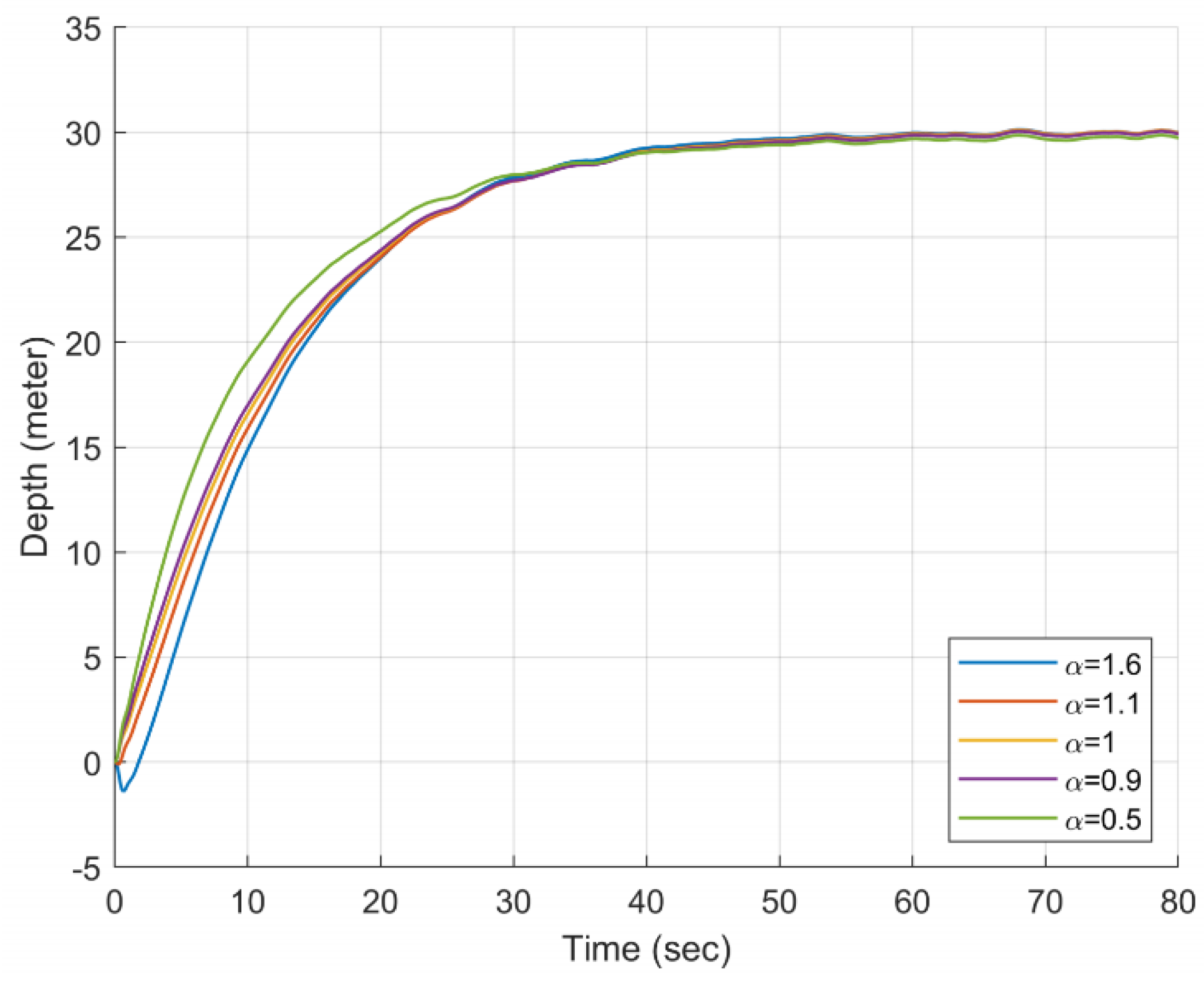
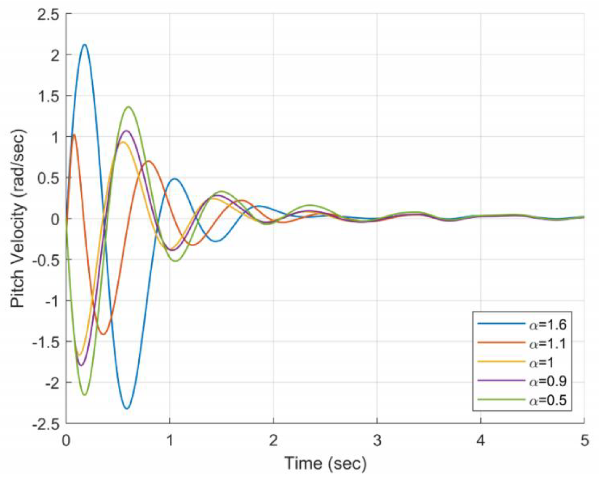
To illustrate the reasons for adopting order selectors in the controller, the following comparative experiments are designed. The controller in the comparative experiment adopts a fixed order, which is selected between ( 0 , 2 ) . Except for the order difference, other parameters are the same among different controllers. The experimental results are shown in Figure 5 and Figure 6. According to the experimental results, the following conclusions can be drawn:
  • For the depth curve, with the increase of α , the adjustment time of the depth gradually decreases, but the change is not large. Smaller orders will perform better on ITAE. When α > 1 , it will cause the propeller to reverse in the early stage of adjustment, which needs to be avoided;
  • For the pitch velocity curve, when α = 1.1 , its extreme value is the smallest, but there are two points to note. First, it causes the propeller to reverse. Second, its extreme value does not appear at the first peak;
  • In the pitch velocity curve, the starting directions of α > 1 and α 1 are different, and the periods of different orders are also different, which provides conditions for the variable order method.
According to the above conclusions, the following order selection algorithm is designed. The variation law of the order mainly depends on the given depth, the real-time depth of the vehicle and the variation of the PWM wave. The key point is to determine t c . t c is the moment when a given depth changes or the UUV is subjected to a large external perturbation resulting in an abrupt change in depth.
The specific way of determining t c is as follows. First, the switching conditions need to be determined. The difference between the given depth and the actual depth at time t is compared with the difference at time t τ and divided by the difference between the given depth at time t and the previous given depth, denoted as r, which is defined as:
r = | | e ( t ) | | e ( t τ ) | z n o w z b e f o r e |
where z n o w is the given depth at this time, and z b e f o r e is the previous given depth. e ( t ) is the depth error at time t , and e ( t τ ) is the depth error at time t τ .
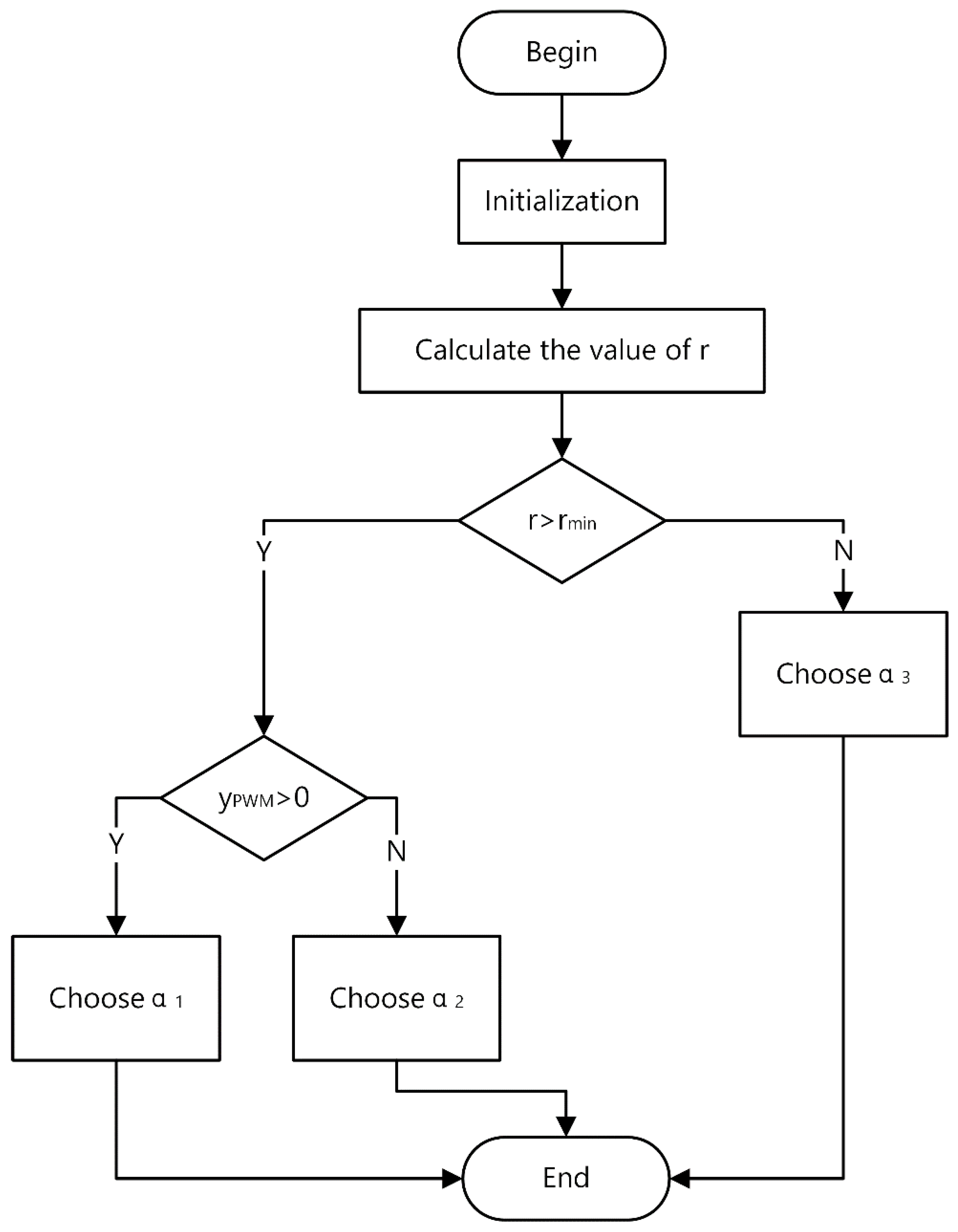
Then, a conditional judgment is made. If r is greater than the minimum allowable ratio r min , it indicates that the time at this time is between t c and t c + τ , and the control method of variable order is adopted. Otherwise, a fixed fractional order is used.
After the time is determined, the change of the order is controlled by the PWM wave to achieve the purpose of reducing the extreme value of the pitch angular velocity:
α = { α 1 α 2 α 3 t c t t c + τ       a n d       y P W M > 0 t c t t c + τ       a n d       y P W M = 0 other   cases
where y P W M is the function value of the PWM wave, 0 < α 1 1 , 1 < α 2 < 2 , 0 < α 3 < 2 . τ is a time delay. Its value is the length of the first cycle of the pitch velocity change curve in the transient process. The whole process is shown in Figure 7. For this method, two points need to be noted:
  • There are two reasons for choosing PWM wave as the judgment condition. On the one hand, the PWM wave does not require additional calculation and will not affect the real-time performance of the control. On the other hand, the PWM wave changes periodically, in harmony with the pitch velocity;
  • α 1 and α 2 are used alternately, and α 1 is before α 2 . This has two advantages. Not only can the influence of reversal be avoided, but also the extreme value of the pitch velocity can be reduced by the characteristic of the opposite starting direction;
  • The PWM wave resets when the given depth changes, which ensures that the PWM wave matches the pitch velocity curve;
  • In theory, the continuous change of order will have better control performance, but it requires a lot of computing resources and is not suitable for UUV.

2.1.3. Scale Factor Selector

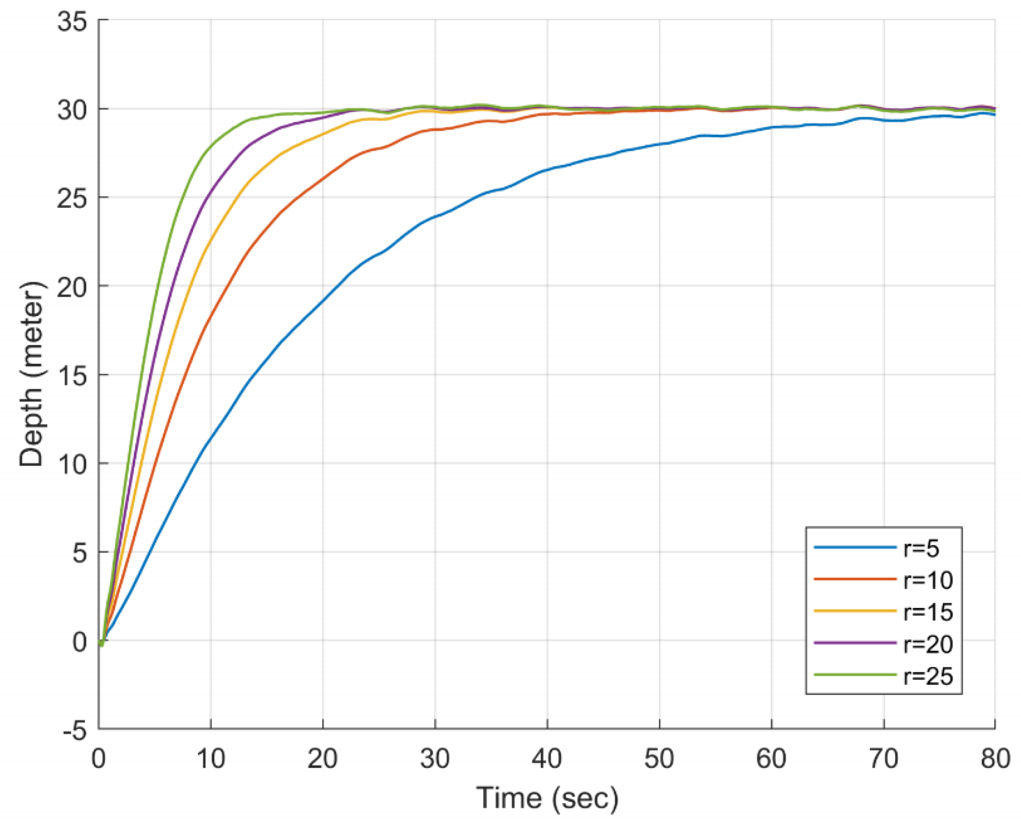
To design the scale factor selector used in the controller, the following comparative experiments are designed. The order of the controller in the comparative experiment is 1.1, and the scale factor is selected between (5, 25). Except for the different scale factors, other parameters are the same among different controllers. The experimental results are shown in Figure 8 and Figure 9. According to the experimental results, the following conclusions can be drawn:
  • Larger scale factor has smaller depth adjustment time and smaller steady-state error;
  • A smaller scale factor can reduce the extreme value of the pitch angular velocity.
In order to combine the advantages of both, the following order selection algorithm is designed.
In the dynamic process, the smaller factor is used in the shorter time when the depth error abruptly occurs, and the larger factor is used in the subsequent adjustment process. The change in the scale factor should preferably be gentle so that it does not have a large impact on the pitch velocity.
In the steady-state process, a larger factor is adopted in the case of bounded external perturbations to further reduce the steady-state error. However, when the UUV encounters a short-term and large-scale disturbance similar to the internal wave flow in the South China Sea, a smaller factor is used to maintain the balance of the UUV [21]. It is best to change the scale factor quickly so that unexpected situations can be dealt with in a timely manner.
Based on this idea, the scale factor function is improved by the softsign function, and the scale factor function is defined as:
r c = { 1 2 ( b a 1 ) k 1 x + m 1 1 + | k 1 x + m 1 | + 1 2 ( b + a 1 )     x p < x 1 2 ( b a 2 ) k 2 x + m 2 1 + | k 2 x + m 2 | + 1 2 ( b + a 2 )     x e < x x p b                                                                                         0 < x x e
where b is the upper bound of the scale factor, and a 1 and a 2 are the lower bounds of the scale factor, as well as the vertical stretch and translation transformations of the original function. k 1 , k 2 , m 1 and m 2 are mainly for the original function of the horizontal expansion and translation transformation. It is also the adjustment of the speed of change and the position of the center of symmetry. x p and x e are used to determine the range of steady-state error and maximum acceptable disturbance, and the values are determined by the actual situation. In this controller, x p = 2 % , x e = 0.3 % . x is defined as:
x = | z n o w z a c t u a l z n o w z b e f o r e |
where z a c t u a l is the actual depth. In this way, the depth change can be judged by x .

2.2. Controller Parameter Optimization Method Based on NSGA-II

The NSGA-II algorithm is a commonly used multi-objective optimization algorithm. The controller adopts this algorithm as the optimization algorithm of the controller parameters, mainly based on the following two reasons:
  • In the actual depth control of UUV, the requirements for control performance are different in different situations. For example, when the UUV performs an emergency salvage or rescue mission, it is hoped that the adjustment time is as short as possible, and its balance can be appropriately relaxed. In the case of UUVs equipped with precision instruments, it is hoped that the bumps will be as small as possible in the case of external disturbances, and the requirements for adjustment time can be appropriately relaxed. At this time, the single-objective optimization algorithm cannot meet the actual needs.
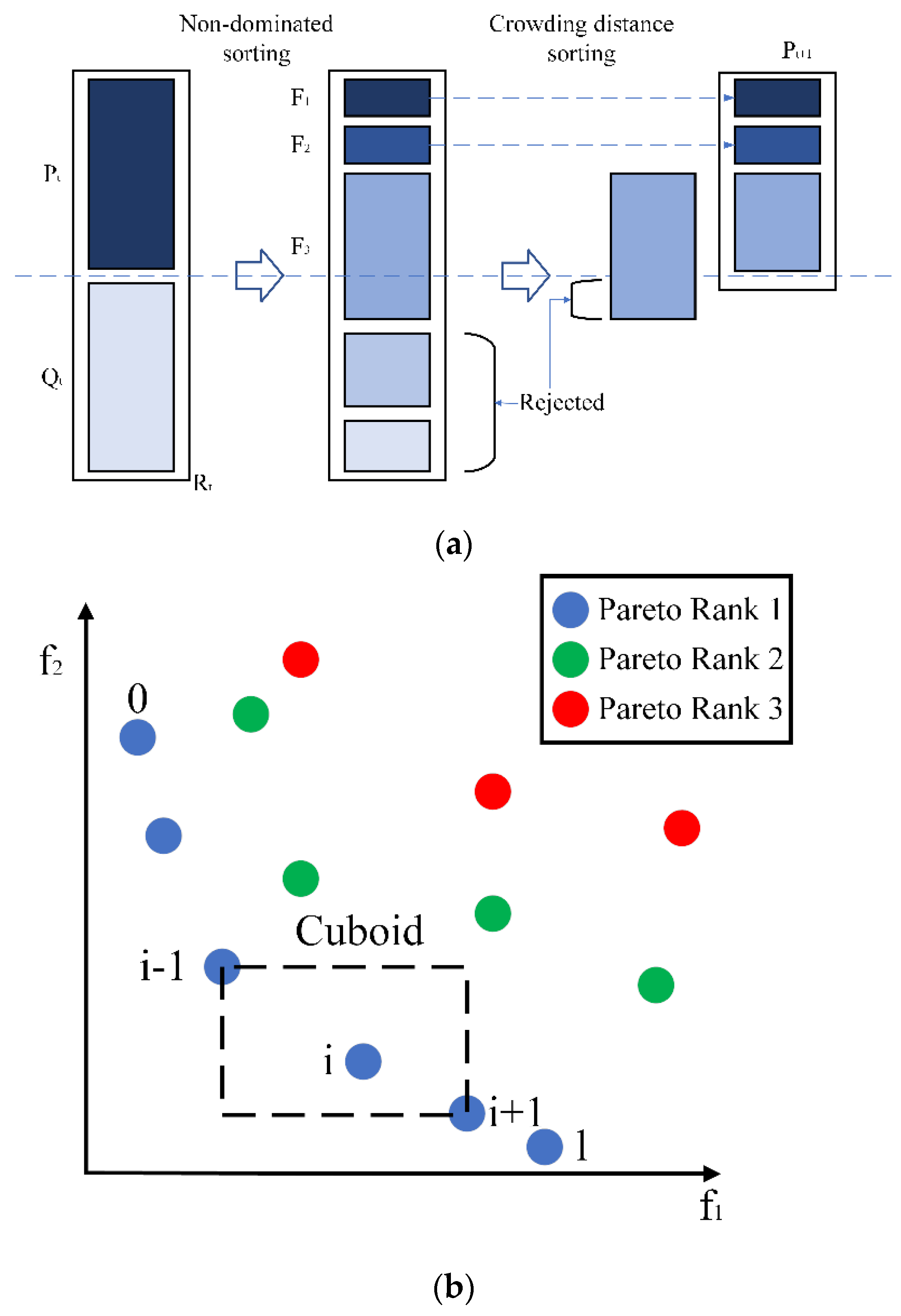
  • In the field debugging of UUV, it is often necessary to combine parameter optimization with physical experiments to obtain the best control performance. This requires the optimization algorithm to have a faster execution speed. However, NSGA-II adopts a fast non-dominated sorting algorithm, and the computational complexity is greatly reduced compared to NSGA.

2.2.1. Optimization Objective

The optimization objectives are the adjustment time ( t s ) of the depth, the ITAE index of the depth and the extreme value of the pitch velocity ( q e x t r e m u m ). t s and q e x t r e m u m reflect the dynamic performance of the controller, and ITAE can better suppress long-term errors.

2.2.2. Parameters to Be Optimized

For the controller parameters, it is obviously unreasonable that all parameters are determined by the optimization algorithm, which will greatly increase the computational complexity, and some parameters can be determined entirely by experience. The parameters optimized by the optimization algorithm include k, a1, a2, b1, b2, a3 and the period and pulse width of the PWM wave. Other parameters and the value range of the optimized parameters are selected according to experience and conditions. The whole process will be demonstrated through concrete examples in comparative experiments. The flow of NSGA-II for VD-SIFLC is shown in Figure 10 [23].

2.3. UUV Model and External Disturbance Model

2.3.1. UUV Model for Depth Control

For the depth control of UUV, in order to make it conform to the actual situation, the following assumptions need to be made.
  • It is assumed that the origin of the coordinates coincides with the center of gravity of the UUV. The heading angular velocity ( r ) and the translational and rotational velocity ( v ) relative to the motion coordinate system are all zero;
  • When the UUV is navigating in the vertical plane, it can be assumed that the UUV is advancing at a constant speed, and the roll and yaw are negligible;
  • At steady state, θ 0 is constant and q 0 = ϕ 0 = 0 .
According to the above assumptions, the following kinetic equation can be obtained. The entire model is expressed in the form of a matrix. The model is as follows:
[ Z w m u 0 Z q 0 0 M w m x G u 0 M q ˙ 0 0 0 1 0 0 1 0 u 0 0 ] [ w q θ z ] + [ m Z w ˙ m x G Z q ˙ 0 0 m x G M w ˙ I y M q ˙ 0 0 0 0 1 0 0 0 0 1 ] [ w ˙ q ˙ θ ˙ z ˙ ] = [ Z δ M δ 0 0 ] δ S
The UUV model adopted in this paper sails at a constant speed of u 0 = 4.11 m / s . Using the state space model, the dynamic equation can be further expressed as:
[ 0.6529 2.4522 0.0855 0 3.2219 3.1309 44.6794 0 0 1 0 0 1 0 4.11 0 ] [ w q θ z ] + [ 0.4147 3.6757 0 0 ] u + [ 0 0 0 1 ] d ( t ) = [ w ˙ q ˙ θ ˙ z ˙ ]
It should be pointed out that external disturbances only directly affect the depth, and the disturbance acts on the whole UUV system, not the control input.

2.3.2. External Disturbance Modeling

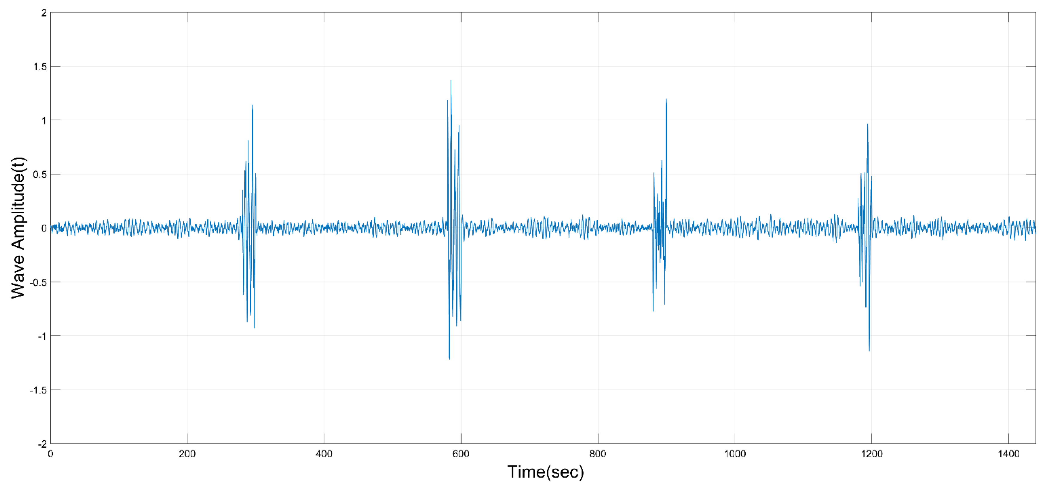
Under water, the external disturbance mainly includes two parts. Part of it is conventional ocean wave disturbance, which is characterized by boundedness, small amplitude and long duration. The other part is a sudden strong disturbance, which is characterized by large amplitude and short duration. The internal wave current in the South China Sea is a typical example. The South China Sea is a sea area with frequent occurrence of internal waves, which are characterized by fast flow and strong suddenness. When the UUV encounters the internal wave flow, it will cause a drastic change in the motion of the UUV.
Both of these disturbances can be described by the ocean wave model. The model uses a robust parameter estimation algorithm and introduces a damping term in the oscillator. Its transfer function can be written as:
h ( s ) = K w s s 2 + 2 ξ w 0 + w 0 2
K w = 2 ξ w 0 σ w
The value of K w needs to be determined according to the actual situation, ζ is the relative damping ratio, w 0 is the peak frequency of the wave spectrum, and σ w is the wave strength. The value range of relative damping ratio is 0.01 < ζ < 0.1 . The value range of the general wave is 0.3 rad / s < w 0 < 1.3 rad / s . For conventional wave disturbance, the value is ζ = 0.1 , σ w = 0.5 and w 0 = 1.2 [23]. For sudden strong disturbances, ζ = 0.1 , σ w = 5 and w 0 = 1.2 [24]. The variation of waves with time is shown in Figure 11.

3. Results

This section mainly gives the method of parameter initialization and comparative test. Comparative experiments verify the effectiveness of the proposed scheme by comparing the dynamic and steady-state control performance of VD-SIFLC and SIFLC.

3.1. Parameter Initialization

Parameter initialization mainly adopts the combination of empirical parameter adjustment method and NSGA-II. On the one hand, if all parameters are optimized with NSGA-II, it will cause the optimization algorithm to run too long. On the other hand, some parameters can be determined empirically and can be fixed.

3.1.1. Empirical Parameter Adjustment

The parameters determined by experience are characterized by universality and little difference in influence on different solutions. In the controller, τ = 1 , α 1 = 1 , α 2 = 1.3 , r min = 0.1 , k 1 = 10 , m 1 = 5 , k 2 = 100 , m 2 = 0.3 .

3.1.2. Generation of Pareto Optimal Solution Set

Before generating the pareto solution set, constraints need to be given. For VD-SIFLC, the constraints are shown in Table 4.
The optimization function adopts the gamultiobj function in MATLAB, and the optimized pareto optimal solution set is shown in Table 5 [25].

3.2. Comparison of Experimental Results

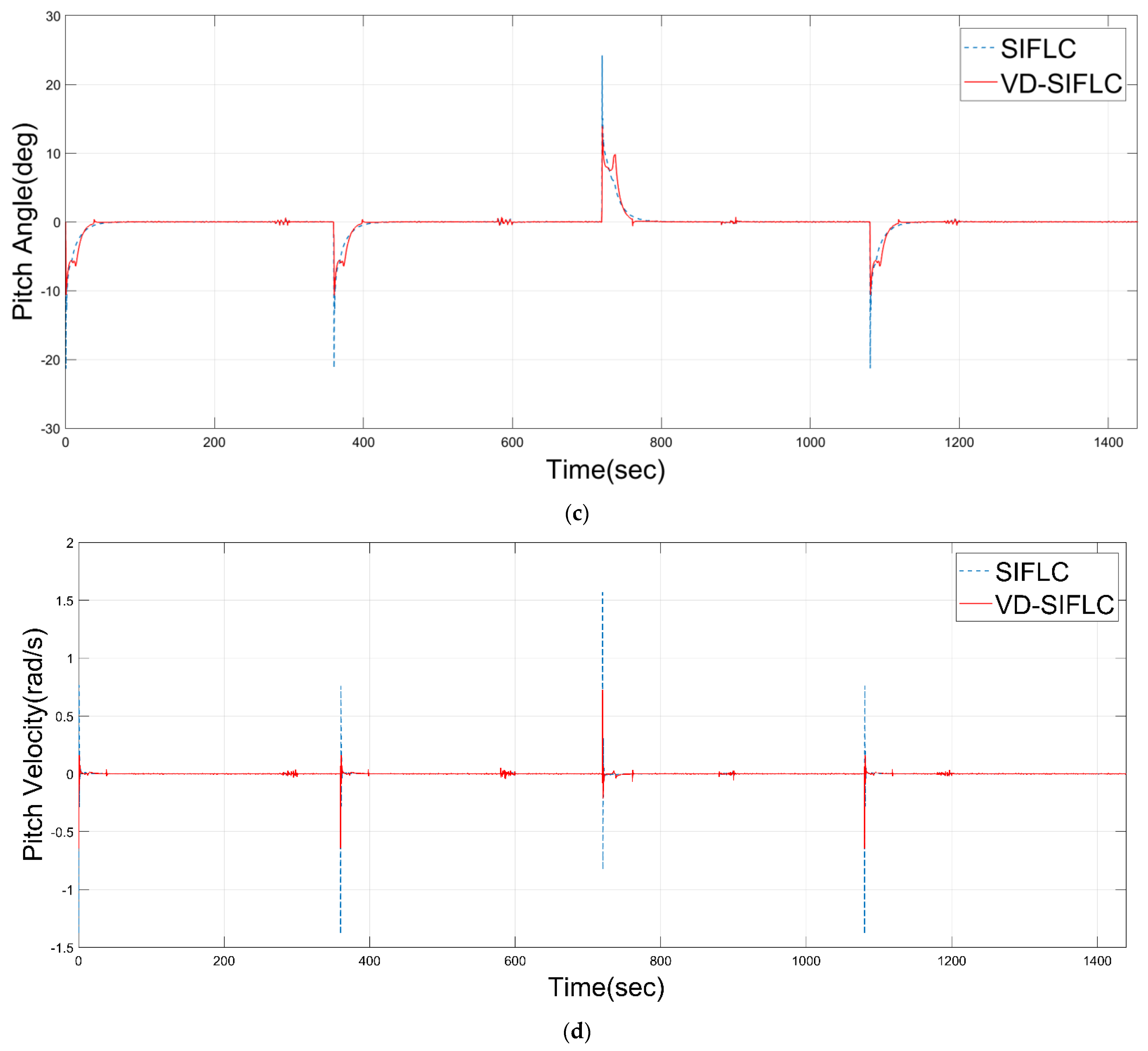
The parameters in the comparison experiment take the first solution in the pareto solution set. Two control groups, SIFLC-A and SIFLC-B, were set up. The former makes the ITAE approximately equal by adjusting the value of k , while the latter selects k = b . Several indicators are selected to measure the control performance of the controller in an all-round way. The control performance comparison results are shown in Figure 12, Table 6 and Table 7. There are two things to note about control performance:
  • The error integral criterion is a performance index expressed by the integral expression of a function of the deviation between the expected output of the system and the actual output or the main feedback signal. Integrated Time and Absolute Error (ITAE) is a method of integrating the time after multiplying the absolute value of the error by time. Its expression is:
y I T A E = 0 t | e ( t ) | d t
  • The control system designed according to this criterion has small transient response oscillation and good selectivity to parameters. Thus, it can be used to measure depth changes.
  • Integral square error (ISE) is to integrate the time after squaring the absolute value of the error. Its expression is:
y I S E = h d _ b e g i n h d _ e n d [ e ( t ) ] 2 d t
  • The integration interval is only during the huge disturbance period. The control system designed according to this criterion often has a faster response speed. Therefore, it is used to measure the change of pitch velocity, so that the system will have better robustness.
2.
The scale factor of VD-SIFLC will be actively reduced when encountering strong disturbance to improve the anti-jamming ability.

4. Discussion

According to the experimental results of VD-SIFLC and SIFLC, the former has better dynamic and steady-state performance than the latter. Especially regarding the extreme value of pitch angular velocity and pitch angle, the former is only about 60% and 70% of the latter. The comparison results in Table 7 demonstrate that the use of the scale factor selector also improves the disturbance immunity of the system. The simulation is an ultra-real-time simulation, and the ratio of the system simulation time to the actual system time is about 6:1.

5. Conclusions

In this paper, a variable-order fuzzy logic controller based on NSGA-II for dynamic parameters of unmanned underwater vehicles is proposed. The design of the order selector and scale factor selector of the proposed controller can improve the controlled system dynamic, steady-state performance and robustness. The controller structure is relatively simple, and the computational complexity is relatively small which is applied on a UUV. Multiple non-inferior solutions were obtained by using the multi-objective genetic algorithm. The users can select appropriate parameters according to the specific requirements of the task, which is more in line with the actual needs. In our future research, the UUV actuator fault and state quantification will be taken into account, and the controller performance will be verified in actual experiments.

Author Contributions

Conceptualization, L.L. and B.Z.; methodology, B.Z.; software, B.Z.; validation, B.Z.; investigation, M.L. and Y.C.; writing—original draft preparation, B.Z.; writing—review and editing, L.L.; visualization, Y.D., P.D. and J.L.; supervision, L.Z. All authors have read and agreed to the published version of the manuscript.

Funding

This research was funded by the National Natural Science Foundation of China under Grant 52001259, 11902252; the Young Talent fund of University Association for Science and Technology in Shaanxi, China under Grant 20200502; Science and Technology on Avionics Integration Laboratory and Aeronautical Science Foundation of China under Grant 201955053003; Maritime Defense Technology Innovation Center Innovation Fund under Grant JJ-2021-702-09; National Research and Development Project under Grant2021YFC2803000; the Shenzhen Science and Technology Program under Grant JCYJ20210324122010027; the Guangdong Basic and Applied Basic Research Foundation under Grant 2019A1515111073; the Science and Development Program of Local Lead by Central Government, Shenzhen Science and Technology Innovation Committee under Grant 2021Szvup111.

Institutional Review Board Statement

Not applicable.

Informed Consent Statement

Not applicable.

Data Availability Statement

Not applicable.

Conflicts of Interest

The authors declares no conflict of interest.

References

  1. Xie, T.; Li, Y.; Jiang, Y.; Pang, S.; Wu, H. Turning circle based trajectory planning method of an underactuated AUV for the mobile docking mission. Ocean. Eng. 2021, 236, 109546. [Google Scholar] [CrossRef]
  2. Wang, T.; Zhao, Q.; Yang, C. Visual navigation and docking for a planar type AUV docking and charging system. Ocean. Eng. 2021, 224, 108744. [Google Scholar] [CrossRef]
  3. Ishaque, K.; Abdullah, S.; Ayob, S.; Salam, Z. A simplified approach to design fuzzy logic controller for an underwater vehicle. Ocean. Eng. 2011, 38, 271–284. [Google Scholar] [CrossRef]
  4. Aras, M.S.M.; Azmi, M.W.N.; Kamaruddin, M.N.; Harun, M.H.; Kasno, M.A. A study of tuning process of fuzzy logic controller output membership function for AUV pitch control. In Proceedings of the 2017 IEEE 7th International Conference on Underwater System Technology: Theory and Applications (USYS), Kuala Lumpur, Malaysia, 18–20 December 2017; pp. 1–5. [Google Scholar]
  5. Tuan, P.V.; Shpektorov, A.G. Comparative analysis of fuzzy regulators for controlling the movement of an autonomous underwater vehicle. In Proceedings of the 2018 IEEE Conference of Russian Young Researchers in Electrical and Electronic Engineering (EIConRus), St. Petersburg, Russia, 29 January–1 February 2018; pp. 954–957. [Google Scholar]
  6. Tuan, P.V. Fuzzy Control of the Stabilization Process of Remote-controlled Underwater Robot. In Proceedings of the 2020 XXIII International Conference on Soft Computing and Measurements (SCM), St. Petersburg, Russia, 27–29 May 2020; pp. 133–136. [Google Scholar]
  7. Han, L.; Tang, G.; Xu, R.; Zhou, Z.; Liu, Z.; Qian, J. Double loop fractional integral sliding mode trajectory tracking control for an underwater manipulator. In Proceedings of the 2018 IEEE 8th International Conference on Underwater System Technology: Theory and Applications (USYS), Wuhan, China, 1–3 December 2018; pp. 1–6. [Google Scholar]
  8. Liu, L.; Wang, J.; Zhang, L.; Zhang, S. Multi-AUV dynamic maneuver countermeasure algorithm based on interval information game and fractional-order DE. Fractal Fract. 2022, 6, 235. [Google Scholar] [CrossRef]
  9. Liu, L.; Zhang, L.; Pan, G.; Zhang, S. Robust yaw control of autonomous underwater vehicle based on fractional-order PID controller. Ocean. Eng. 2022, 257, 111457. [Google Scholar] [CrossRef]
  10. Konar, S.; Patil, M.D.; Vyawahare, V.A. Design of a fractional order sliding mode controller for depth control of AUV. In Proceedings of the 2018 Second International Conference on Intelligent Computing and Control Systems (ICICCS), Madurai, India, 14–15 June 2018; pp. 1342–1345. [Google Scholar]
  11. Jia, L.Y.; Zhu, Z.Y. Improved fractional-order integral sliding mode control for AUV based on RBF neural network. In Proceedings of the 2019 Chinese Automation Congress (CAC), Hangzhou, China, 1–3 December 2019; pp. 4809–4814. [Google Scholar]
  12. Liu, L.; Zhang, L.; Zhang, S. Robust PI lambda controller design for AUV motion control with guaranteed frequency and time domain behaviour. IET Control. Theory Appl. 2020, 15, 784–792. [Google Scholar] [CrossRef]
  13. Xue, D.; Li, T.; Liu, L. A MATLAB toolbox for multi-variable linear fractional-order control systems. In Proceedings of the 2017 29th Chinese Control And Decision Conference (CCDC), Chongqing, China, 28–30 May 2017; pp. 1894–1899. [Google Scholar]
  14. Xue, D.; Chen, Y. Modeling, Analysis and Design of Control Systems in MATLAB and Simulink; World Scientific Press: Singapore, 2014. [Google Scholar]
  15. Wan, J.; He, B.; Wang, D.; Yan, T.; Shen, Y. Fractional-order PID motion control for AUV using cloud-model-based quantum genetic algorithm. IEEE Access 2019, 7, 124828–124843. [Google Scholar] [CrossRef]
  16. Zhang, S.; Liu, L.; Xue, D.; Chen, Y. Stability and resonance analysis of a general non-commensurate elementary fractional-order system. Fract. Calc. Appl. Anal. 2020, 23, 183–210. [Google Scholar] [CrossRef]
  17. Zhang, S.; Liu, L.; Xue, D. Nyquist-based stability analysis of non-commensurate fractional-order delay systems. Appl. Math. Comput. 2020, 377, 125111. [Google Scholar] [CrossRef]
  18. Healey, J.; David, L. Multivariable sliding mode control for autonomous driving and steering of unmanned underwater vehicles. IEEE J. Ocean. Eng. 1993, 18, 327–339. [Google Scholar] [CrossRef]
  19. Fossen, T.I.; Sagatun, S.I. Adaptive control of nonlinear systems: A case study of Underwater robotic systems. J. Robot. Syst. 1991, 8, 393–412. [Google Scholar] [CrossRef]
  20. Saelid, S.; Jenssen, N.; Balchen, J. Design and analysis of a dynamic positioning system based on Kalman filtering and optimal control. IEEE Trans. Autom. Control. 1983, 28, 331–339. [Google Scholar] [CrossRef]
  21. Dong, D.; Yang, X.; Li, X.; Li, Z. SAR Observation of Eddy-Induced Mode-2 Internal Solitary Waves in the South China Sea. IEEE Trans. Geosci. Remote Sens. 2016, 54, 6674–6686. [Google Scholar] [CrossRef]
  22. Choi, B.; Kwak, S.; Kim, B.K. Design and stability analysis of single-input fuzzy logic controller. IEEE Trans. Syst. Man Cybern. Part B 2000, 30, 303–309. [Google Scholar] [CrossRef] [PubMed] [Green Version]
  23. Dong, W.; Huang, Y.; Lehane, B.; Ma, G. Multi-objective design optimization for graphite-based nanomaterials reinforced cementitious composites: A data-driven method with machine learning and NSGA-II. Constr. Build. Mater. 2022, 331, 127198. [Google Scholar] [CrossRef]
  24. Zhang, X.; Zhang, T.; Li, X. Satellite-data-driven propagation speed model for internal solitary waves in the shallow and deep oceans. In Proceedings of the IEEE International Geoscience and Remote Sensing Symposium IGARSS, Brussels, Belgium, 11–16 July 2021; pp. 7402–7405. [Google Scholar]
  25. Lin, J.; Niu, Z.; Zhang, X.; Ma, H.; Zhao, Y.; Han, Q. Clamp nonlinear modeling and hysteresis model parameter dentification. IEEE Access 2021, 9, 147757–147767. [Google Scholar] [CrossRef]
Figure 1. UUV depth control system block diagram.
Fractalfract 06 00577 g001
Figure 2. Structure block diagram of variable-order fuzzy logic controller with dynamic parameters.
Fractalfract 06 00577 g002
Figure 3. Input membership function.
Fractalfract 06 00577 g003
Figure 4. Output membership function.
Fractalfract 06 00577 g004
Figure 5. Variation of depth at different orders (the positive direction of the depth is the water surface down).
Fractalfract 06 00577 g005
Figure 6. Variation of pitch velocity at different orders.
Fractalfract 06 00577 g006
Figure 7. Order selection algorithm flow chart.
Fractalfract 06 00577 g007
Figure 8. Variation of depth at different scale factors.
Fractalfract 06 00577 g008
Figure 9. Variation of pitch velocity at different scale factors.
Fractalfract 06 00577 g009
Figure 10. (a) Fast non-dominated sort; (b) elitist selection.
Fractalfract 06 00577 g010
Figure 11. The variation of waves with time.
Fractalfract 06 00577 g011
Figure 12. Variation of various parameters of VD-SIFLC and SILFC with time: (a) depth; (b) heave velocity; (c) pitch angle; (d) pitch velocity.
Fractalfract 06 00577 g012aFractalfract 06 00577 g012b
Table 1. The meaning of each parameter in the control system.
Parameter NameDefinition
m Mass of unmanned underwater vehicle
M Hydrodynamic added mass
w Heave velocity of unmanned underwater vehicle
q Pitch velocity of unmanned underwater vehicle
θ Pitch angle of unmanned underwater vehicle
z Depth of unmanned underwater vehicle
I y Moment of inertia about the x-axis
k Scale factor in VD-SIFLC
τ Time delay (judgment condition for order selection)
Table 2. General rule table with e and e ˙ as control inputs.
e PLPMPSZNSNMNL
e ˙
NLZNSNMNLNLNLNL
NMPSZNSNMNLNLNL
NSPMPSZNSNMNLNL
ZPLPMPSZNSNMNL
PSPLPLPMPSZNSNM
PMPLPLPLPMPSZNS
PLPLPLPLPLPMPSZ
Table 3. Simplified rule table using e and D t α a f ( t ) as control inputs.
d F D L N L L N M L N S L Z L P S L P M L P L
u 0 NLNMNSZPSPMPL
Table 4. Constraints for NSGA-II.
Order Selector ParametersRangesScale Factor Selector ParameterRanges
α 3 ( 0 , 2 ) b ( 8 , 15 )
Period of PWM ( T P W M ) ( 0.1 , 0.3 ) a 1 ( 3 , 6 )
Duty cycle of PWM ( D P W M ) ( 30 , 40 ) a 2 ( 0.5 , 2 )
k ( 0.5 , 5 ) --
Table 5. Generation of pareto optimal solution set.
Number k b a 1 a 2 α 3 T P W M D P W M t s ITAE q e x t r e m u m
11.512410.13244.07321.14671.09730.200033.321441.0227 e 14.5256 0.7244
20.50008.00003.00001.45270.92310.100030.000099.6377 e 15.3146 0.6575
32.394813.98843.95500.79711.21320.284036.375929.6883 e 14.3178 1.2966
41.03778.00003.00000.50000.92310.300030.500063.2331 e 14.9000 0.6863
54.208914.58243.06951.93061.41230.298235.293029.5043 e 14.3711 1.3252
64.854114.58245.64591.69890.69370.239037.967525.5903 e 14.1020 2.0584
73.422413.60745.38711.63300.84210.251937.391527.7956 e 14.1697 1.7542
Table 6. Control performance comparison.
Control Performance IndicatorsVD-SIFLCSIFLC-A
Settling time (2%)
for depth ( Z )
(s)
38.006552.4642
32.924443.6799
69.004375.3802
35.477148.3702
Extreme value
for pitch velocity ( q )
(rad/s)
−0.6452−1.3921
−0.6439−1.3910
0.72441.5656
−0.6452−1.3909
Extreme value
for pitch angle ( θ )
(deg)
−10.6345−21.3625
−10.6246−21.2916
13.859224.2020
−10.6077−21.3022
ITAE
for depth ( Z )
e 14.5276 e 14.5584
Table 7. Robustness comparison of VD-SIFLC and SIFLC.
ISE for Pitch Velocity ( q )
during Internal Wave Action
VD-SIFLCSIFLC-B
0–3600.13480.1457
360–7200.17980.1921
720–10800.09690.1252
1080–14400.11650.1227
Publisher’s Note: MDPI stays neutral with regard to jurisdictional claims in published maps and institutional affiliations.