Article

A Multiscale Accuracy Degradation Prediction Method of Planetary Roller Screw Mechanism Based on Fractal Theory Considering Thread Surface Roughness

1
Chinese Helicopter Research & Development Institute, Jingdezhen 333001, China
2
School of Mechatronics Engineering, Nanchang University, Nanchang 330031, China
*
Author to whom correspondence should be addressed.
Fractal Fract. 2021, 5(4), 237; https://doi.org/10.3390/fractalfract5040237
Submission received: 8 October 2021 / Revised: 11 November 2021 / Accepted: 16 November 2021 / Published: 22 November 2021

Abstract

:
The wear problems are vital to the planetary roller screw mechanism (PRSM) as they have a great influence on transmission accuracy, working efficiency, and service life. However, the wear characteristics of the PRSM have been rarely investigated in the past. In this paper, a multiscale adhesive wear model is established by incorporating the effective wear coefficient and considering the thread surface roughness. The variation of surface roughness is characterized by the two-dimension Majumdar–Bhushan (MB) function. The multi-asperity contact regimes are used to estimate microcontact mechanics of the rough interface. Moreover, the influences of surface roughness, material properties, and working conditions on the wear depth and precision loss of the PRSM are studied in detail. The results reveal that as the surface roughness increases, the total actual contact area, wear depth, and precision loss rate rise. In addition, the adhesive wear increases with the growth of the axial load, and decreases with the increase in the material hardness and material elastic modulus ratio to a certain extent. The investigation opens up a theoretical methodology to predict the wear volume and precision loss with regard to thread surface roughness, which lays the foundation for the design, manufacturing, and application of the PRSM.

1. Introduction

As an essential transmission component of linear motion of electromechanical systems, the planetary roller screw mechanism (PRSM) is widely applied in electric aircrafts [1], automobile, robots, and defense equipment. In these engineering applications, high precision, heavy load, lightweight, and long service life are strongly required. In the PRSM, the wear is inevitable due to relative sliding and large contact stress, which greatly affects the transmission accuracy and lifetime in the running process. Therefore, it is indispensable to calculate wear volume and predict precision loss. The wear is influenced by many factors, including surface roughness, material hardness, material elastic modulus, and operating condition [2], while the effect of these factors on the contact and wear mechanism of the PRSM is almost ignored.
Considerable research efforts have been devoted to contact analysis [3,4], kinematics [4,5], statics [6,7,8], and dynamics [9,10]. Sandu et al. [11,12] proposed an efficient method for analyzing thread profile and predicted threaded contact area. Fu et al. [13] established a comprehensive contact model, and revealed that contact positions and contact clearances at the screw–roller and roller–nut interfaces were influenced by manufacturing errors and misaligned errors. Jones et al. [14] presented in-plane slip velocity caused by relative slip at the screw–roller interface and by pitch deviation at the roller–nut interface. Du et al. [15] proposed a modified load distribution model by considering both axial load and radial load, and showed that the contact forces and fatigue life were influenced by the variation of external loads and machining errors. Ma et al. [16] reported the friction nature of the mating thread surface and revealed the normal pressure and friction force distributions. Xie et al. [17] indicated the mixed-lubrication model, and showed that the film thickness, film pressure, and friction coefficient were affected by surface roughness, rotational speed, and axial load. Fu et al. [18] analyzed the dynamic behaviors were affected by roller number, pitch, and flank angle. The above researches have paved the way for wear analysis of the PRSM. In the past, only Aurégan et al. [19,20] studied some wear characteristics of the PRSM by tribometer, and revealed that the creep ratio played an important role in adhesive wear. However, the previous experimental mechanism was slightly different from the wear mechanism of the PRSM and the corresponding wear theory was not established. In the past two decades, there has been increasingly more attention to the investigation of wear mechanism based on the fractal theory [21] and Archard’s wear law [22], because multiscale contacts and wear characteristics could be presented. This way was applied in gear [23], rolling bearing [24,25], ball screw [2], and sliding screw [26]. Wang et al. [27,28] showed the fractal characterization of rough surfaces and revealed the interfacial temperature distribution. Yan et al. [29] proposed a modified two-variable Weierstrass–Mandelbort (WM) function, and characterized the rough surface. The total actual normal contact force and contact area were presented by incorporating in fractal parameters and material properties. Sahoo et al. [30] estimated the adhesive wear by considering the influence of scale-dependent surface topography, and revealed that the wear volume relied on the normal load and adhesion arising out of surfaces. Yin et al. [31] studied the adhesive wear based on three-dimensional fractal surfaces. The results indicated that surface roughness, material properties, and work of adhesion had a great influence on the asperity plastic deformation, wear rate, and wear coefficient. Tan et al. [26] proposed a wear model of the plane sliding pair to estimate the wear resistance, and revealed the influences of interfacial topography, material properties, and operating conditions on the wear behaviors. To sum up, the adhesive wear was significantly related to the surface roughness, material properties, and working conditions. Moreover, the contact and wear of the PRSM only occurred on the contact ellipse part at a certain time, and the traditional Archard wear model needed to be modified to predict wear volume accurately. However, the wear characteristic of the PRSM was not researched by considering these factors.
This paper targets at developing an efficient method to predict the wear volume and precision loss by incorporating surface roughness, material properties, and operating conditions. Based on multiscale microcontact mechanics, combined with Archard adhesive wear theory, a multiscale adhesive wear model is established to explore the wear mechanism under the coupling effect of macro meshing and micro topography, and reveal the laws of the wear and precision loss of the PRSM. The main contents of this study are as follows: First, in Section 2, the two-dimension rough profile is characterized by MB function, and the multi-asperity contact regimes, which include the elastic contact, first elastoplastic contact, second elastoplastic contact and plastic contact, are used to calculate microcontact mechanics. Moreover, the multiscale adhesive wear model based on Archard’s theory is derived by incorporating the effective wear coefficient and microcontact mechanics of the rough surface. Then, in Section 3, the effects of the surface roughness, material hardness, material elastic modulus ratio, axial load and rotational speed on the actual contact area, wear depth and precision loss rate are discussed in detail. Finally, in Section 4, the important contributions and conclusions are listed.

2. Multiscale Adhesive Wear Model

The structure of the PRSM is shown in Figure 1. In the PRSM, the adhesive wear mainly focuses on two rough mating thread surfaces at the screw–roller side, because the main contact mode at the screw–roller side is sliding contact and at the roller–nut side is rolling contact [16]. Hence, in this paper, the investigation of wear characteristic concentrates on the screw–roller side. In order to effectively predict the adhesive wear of the PRSM, the multiscale wear evaluation mechanism is introduced, as shown in Figure 2. It can be found from Figure 2a, the macro contact mode of the PRSM is point contact at the screw–roller side. In the previous wear model of the PRSM, it is assumed that the thread surfaces of the screw and roller are enough smoothing. However, the thread surface is rough enough when viewed microscopically. In order to predict the wear volume of the PRSM more accurately, the fractal characterization of rough thread surface of the screw and roller is considered in detail. It can be evidently seen from Figure 2b that two mating rough surfaces are multi-asperity contacts at the screw–roller side for each contact ellipse, and the multi-asperity microcontacts between two rough surfaces can be equivalent to a rough-on-rigid solution based on Wang’s analysis [32]. Moreover, Figure 2d illustrates the multi-asperity contacts under the normal force have different contact regimes, such as elastic deformation, elastoplastic deformation and plastic deformation, among which the plastic deformation is the most important factor causing wear. The representative wear stages presented in Figure 2f are divided into running-in, mild wear and severe wear [33], among which the second is mainly investigated in the paper. To sum up, the multiscale wear model of the PRSM is defined as follows:
V ( t ) = n i = 1 n t K w A r i S ( t )
where, n and nt are the number of the roller and the thread teeth of the roller, respectively. Kw is Archard’s wear coefficient. Ari denotes the total actual contact area at ith contact ellipse, and it is related to normal contact force, material yield strength and surface roughness. S(t) is the relative sliding distance changes with time.

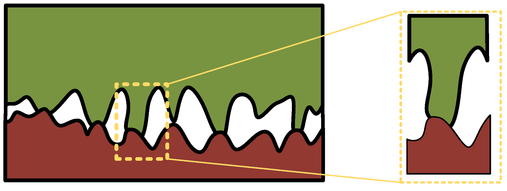
2.1. Rough Surface Characterization

In order to investigate the influence of surface roughness on adhesive wear, the fractal theory is incorporated in the multiscale wear model and used to present the rough surface. The equivalent fractal (rough) surface is characterized by continuity [34], non-differentiability [31] and self-affinity [35] so that it can be close to the actual machining surface. Moreover, the actual surface of the three-dimension topography can be measured by a white light interferometer (Zygo New View 9000), as shown in Figure 3. The corresponding simulated surface can be characterized by the Yan-Komvopoulos (YK) function, the parameters of which can be identified by the measurement result. The YK function is written as [31]:
z ( x , y ) = L ( G L ) ( D 3 2 ) ( ln γ M ) 1 / 2 m = 1 M q = 0 q max γ ( D 3 3 ) q × { cos ϕ m , q cos [ 2 π γ q ( x 2 + y 2 ) 1 / 2 L cos ( tan 1 ( y x ) π m M ) + ϕ m , q ] }
where, L is the sample length. G is the fractal roughness. D3 (2 < D3 < 3) is the three-dimension fractal dimension. M is the number of superimposed ridges. γ is generally equal to 1.5. q is the spatial frequency index. qmax is the upper limit of spatial frequency index and q max = int [ log ( L / L s ) / log γ ] . ϕm,q (0 ≤ ϕm,q ≤ 2π) is a random phase.
In order to simplify the calculation, the Majumdar–Bhushan (MB) function is usually used to characterize the two-dimensional profile of the rough surface and introduced as follows [36]:
z ( x ) = G D 1 ( 2 r ) 2 D cos ( π x 2 r ) , ( r < x < r )
where, D is the two-dimensional fractal dimension. r denotes the contact radius of an asperity contact. The fractal roughness G and surface roughness Ra can be approximated as an exponential relationship, which is defined by:
G = 10 ( 5.26 / R a 0.042 )
In addition, the fractal dimension D (1 < D < 2) can also be obtained by surface roughness Ra, and the relation is expressed by [37]:
D = 1.528 R a 0.042
Substituting Equations (4) and (5) into Equation (3), the relation between fractal function and surface roughness can be expressed by:
z ( x ) = 10 5.26 ( R a 0.042 1.528 ) / R a 0.084 ( 2 r ) 2 1.528 / R a 0.042 cos ( π x 2 r )
During the design and manufacturing, the surface roughness Ra can be considered as a constant, which mainly depends on the accuracy requirement and machining cost. Therefore, the rough two-dimension profile can be effectively characterized by Equation (6).

2.2. Multiscale Contact Mechanic Models

The contact mode at two rough mating surfaces is multi-asperity contact, as shown in Figure 2b. The asperity heights of the thread surface and the contact load at each contact ellipse are significantly different, resulting in a big difference in the microcontact regimes of the asperities. Therefore, it is essential to analyze the various contact mechanism by the single-asperity method, as shown in Figure 4.

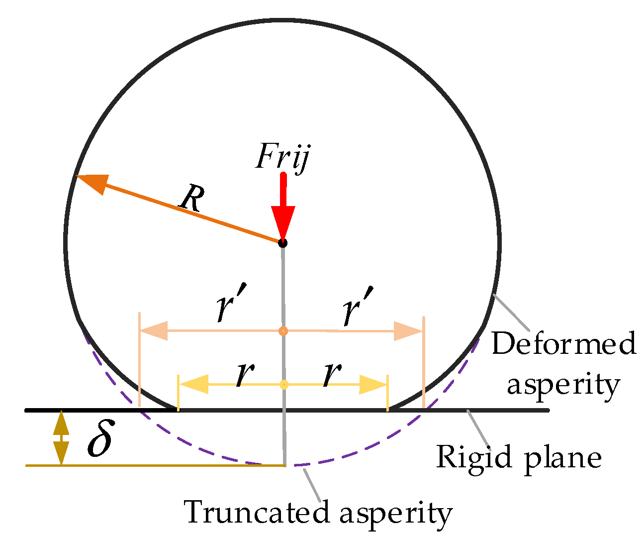
2.2.1. Single Asperity Contact

Figure 5 shows the schematic diagram of microcontact deformation of single asperity. The deformation δ can be considered as the peak-to-valley amplitude of z(x) in accordance with Equation (3) and written as:
δ = G D 1 ( 2 r ) 2 D
and the asperity’s curvature radius of R can be written as:
R = 1 | d 2 z d x 2 | x = 0 = a D / 2 π 2 G D 1
When the asperity under normal load reaches initial yielding, the critical contact deformation can be obtained as:
δ e c = ( 1.4 π K ϕ ) 2 R
where, K is the hardness coefficient and K = 0.454 + 0.41ν. ϕ is equal to σ s / E 0 and E0 is the equivalent Young’s modulus and 1 / E 0 = ( 1 v 1 2 ) / E 1 + ( 1 v 2 2 ) / E 2 . E1 and E2 are Young’s modulus of the screw and the roller, respectively.
Then, the critical elastic contact area corresponding to the critical elastic contact deformation can be expressed as:
a e c = π R δ e c = ( 1.4 π 3 / 2 K ϕ R ) 2
According to You’s conclusion [38], the critical elastoplastic contact area aepc and plastic contact area apc can be defined by:
{ a e p c = 6 1 / ( 1 D ) a e c = 6 1 / ( 1 D ) ( 1.4 π 3 / 2 K ϕ R ) 2 a p c = 110 1 / ( 1 D ) a e c = 110 1 / ( 1 D ) ( 1.4 π 3 / 2 K ϕ R ) 2
Based on the above three critical contact areas, the contact regimes can be divided into four kinds: (1) the fully elastic contact regime ( a e c < a < a L ), and aL denotes the maximum contact area; (2) the first elastoplastic contact regime ( 6 1 / ( 1 D ) a e c < a < a e c ); (3) the second elastoplastic contact regime ( 110 1 / ( 1 D ) a e c < a < 6 1 / ( 1 D ) a e c ); (4) the fully plastic contact regime ( 0 < a < 110 1 / ( 1 D ) a e c ). The contact forces of the asperity under the corresponding contact regime can be written as:
{ F e = 4 π 1 / 2 E 0 G D 1 a ( 3 D ) / 2 / 3 F e p 1 = 0.7521 K H a e c 0.2544 a 1.2544 F e p 2 = 0.9992 K H a e c 0.1021 a 1.1021 F p = H a
where, F e , F e p 1 , F e p 2 , F p are the elastic contact force, first elastoplastic contact force, second elastoplastic contact force and plastic contact force of the asperity, respectively.

2.2.2. Multi-Asperity Contacts

As mentioned in the previous section, there are four different contact regimes and they are mainly dependent on the scale of contact asperity. The size distribution function of the asperity can be expressed as follows [27]:
n ( a ) = { D 2 ψ ( 2 D ) / 2 ( a L ) D / 2 ( a ) ( D + 2 ) / 2 , ( 0 < a < a L ) 0 , ( a L < a < + )
where, ψ is the domain extension factor and can be obtained by:
ψ ( 2 D ) / 2 ( 1 + ψ D / 2 ) ( D 2 ) / D ( 2 D ) / D = 1
Moreover, in the PRSM, the multi-asperity contact regimes of mating surfaces between the roller and the screw could be different at contact positions. Because the normal contact forces of the roller thread teeth at contact positions decrease with the increase in thread number, and the difference between the maximum and the minimum contact force is more than 100 N [8,15]. Especially the contact forces are concentrated on the first few teeth. Therefore, in order to obtain actual contact areas and contact forces accurately, it is essential to implement segmented calculations. When the fractal dimension D is not equal to 1.5, the actual contact areas and contact forces over each contact ellipse can be divided into four cases and described in detail as follows:
(1)
When 0 < a L < a p c , the contact regimes are in full plastic deformation and the actual contact area and contact force can be written as:
A r = 0 a L a p n ( a ) d a
F r = 0 a L F p n ( a ) d a
(2)
When a p c < a L < a e p c , the contact regimes include the plastic and second elastoplastic deformations, and the actual contact area and contact force can be expressed by:
A r = 0 a p c a p n ( a ) d a + a p c a L a e p c n ( a ) d a
F r = 0 a p c F p n ( a ) d a + a p c a L F e p 2 n ( a ) d a
(3)
When a e p c < a L < a e c , the contact regimes include the plastic, second elastoplastic and first elastoplastic deformations, and the actual contact area and contact force can be defined as follows:
A r = 0 a p c a p n ( a ) d a + a p c a e p c a e p 2 n ( a ) d a + a e p c a L a e p 1 n ( a ) d a
F r = 0 a p c F p n ( a ) d a + a p c a e p c F e p 2 n ( a ) d a + a e p c a L F e p 1 n ( a ) d a
(4)
When a e c < a L , the contact regimes include the plastic, second elastoplastic, first elastoplastic and elastic deformations, and the actual contact area and contact force can be written as:
A r = 0 a p c a p n ( a ) d a + a p c a e p c a e p 2 n ( a ) d a + a e p c a e c a e p 1 n ( a ) d a + a e c a L a e n ( a ) d a
F r = 0 a p c F p n ( a ) d a + a p c a e p c F e p 2 n ( a ) d a + a e p c a e c F e p 1 n ( a ) d a + a e c a L F e n ( a ) d a
where, A r is the truncated area and A r = 2 A r .
In order to simplify the calculation, dimensionless variables are introduced by:
{ F r * = F r E 0 A a , F a * = F a E 0 A a , G * = G A a a e c * = a e c E 0 A a , ϕ * = σ s E 0 , A r i * = A r A a
Substituting Equations (12)–(15) into Equation (22), the relation between dimensionless actual contact force and dimensionless contact area can be expressed by:
F r * = f 1 ( D ) A r * D / 2 a e c * ( 2 D ) / 2 + f 2 ( D ) ( A r * a e c * ) D / 2 + f 3 ( D ) A r * D / 2 ( f 4 ( D ) A r * ( 3 2 D ) / 2 a e c * ( 3 2 D ) / 2 )
where, f 1 ( D ) = 5.6 × 110 ( 2 D ) / ( 2 2 D ) ( D 2 D ) ( 2 D ) / 2 ϕ ψ ( D 2 ) 2 / 4 , f 2 ( D ) = 0.457 D ( 2 D ) / 2 2 D ( 2 D ) D / 2 π K 3 ϕ 3 ψ ( D 2 ) 2 / 4 G * 2 ( D 1 ) f 5 ( D ) , f 3 ( D ) = 2 ( 3 D ) / 2 D ( 2 D ) / 2 ( 2 D ) D / 2 3 2 π ( 3 2 D ) ( D 2 D ) ( 2 D ) / 2 ψ ( D 2 ) 2 / 4 , f 4 ( D ) = ( D 2 D ) ( 2 D 3 ) / 2 ψ ( D 2 ) ( 3 2 D ) / 4 , f 5 ( D ) = 1.03 ( 1 6 ( 1.425 0.925 D ) / ( 1 D ) ) 1.425 0.925 D + 1.4 ( 6 ( 1.263 0.763 D ) / ( 1 D ) 110 ( 1.263 0.763 D ) / ( 1 D ) ) 1.263 0.763 D .
When D = 1.5,
F r * = [ 0.7027 φ + 0.9247 G * 1 / 2 a e c * 1 / 4 ln ( A r * 3 ψ 1 / 4 a e c * ) + a e c * 1 / 2 f 6 ( D ) ] ψ 1 / 16 a e c * 1 / 4 A r * 3 / 4
where, f 6 ( D ) = 2.6741 K 3 ϕ 3 G * f 5 ( D ) .
Then, the dimensionless total axial load can be defined by:
F a * = n i = 1 n t F r i *
Substituting Equation (24) into Equation (26), the relation between the total axial load and actual contact area can be expressed by:
F a * = n i = 1 n t { f 1 ( D ) ( A r i * ) D / 2 a e c * ( 2 D ) / 2 + f 2 ( D ) ( a e c * A r i * ) D / 2 + f 3 ( D ) ( A r i * ) D / 2 [ f 4 ( D ) ( A r i * ) ( 3 2 D ) / 2 a e c * ( 3 2 D ) / 2 ] }
It can be found from Equation (27) that the total axial load is a function of the actual contact area. Moreover, when the actual contact force is known at each contact position, the actual contact area can be solved according to Equation (24).

2.3. Macro Contact Forces

The actual contact force at the screw–roller and roller–nut side can be obtained by macro recursive equation of the load distribution and written as [6]:
F r i S R F r i + 1 S R K S R C F a 1 j = 1 i F r j S R K S S F r i + 1 S R F r i S R K S T + j = 1 i ( F r j S R F r j N R ) K R S + F r i + 1 S R F r i S R K R T = 0
F r i N R F r i + 1 N R K N R C + F a 1 j = 1 i F r j N R K N S + F r i + 1 N R F r i N R K N T j = 1 i ( F r j S R F r j N R ) K R S + F r i N R F r i + 1 N R K R T = 0
where, KSRC and KNRC is the normal contact stiffness of the screw and the roller, respectively. KSS and KRS are the shaft section stiffness of the screw and the roller, respectively. KST and KRT are the thread stiffness of the screw and the roller, respectively. Fa1 is the axial load of a roller.
According to Equations (28) and (29), the normal contact force Fri at ith thread tooth can be obtained so that the total actual contact area Ari at ith thread tooth can be solved by Equations (24) and (28).

2.4. Relative Sliding Velocity and Distance

The adhesive wear of the PRSM is mainly caused by the relative sliding, which is derived from the difference in the helix angles between the roller and the screw. Figure 6 shows the schematic diagram of the velocity analysis at the screw–roller interface. In Figure 6, Πs and Πr are the mating thread surface of the screw and roller, respectively. The mating surfaces Πs and Πr coincide at the contact point G’. G is the projection of the contact point G’ in the XsOsYs plane. r s r and r r s are the meshing radii of the screw and the roller, respectively. θ s r and θ r s are the meshing angles of the screw and the roller, respectively. The meshing radii and angles can be obtained by [13]. ω s and ω p are the angular velocity of the screw and the revolution angular velocity of the roller, respectively. In the running process, the screw rotates around its own axis at the speed of ωs, the roller revolves around the screw at the speed of ωp, and at the same time rotates around its own axis at the speed of ωr. The magnitude of the sliding velocity of ith thread tooth at the screw–roller interface can be defined by:
| v i s l i p | = r s r 2 ( ω s ω p ) 2 + ( n s r r s ω p ) 2 2 r s r r r s s s ω p ( ω s ω p ) cos ( θ s r + θ r s ) + ( ω s L s 2 π ) 2
Hence, the sliding distance can be expressed as follows:
S i ( t ) = | v i s l i p | t

2.5. Extended Multiscale Wear Volume and Precision Loss Model

The wear and contact mechanism of the PRSM at the screw–roller interface is shown in Figure 7. It can be found that the contact between the screw and the roller is intermittent in the running processing. It is essential to predict the wear volume considering the partial contact mechanism. Hence, according to the contact and wear characteristics in the actual running processing, the wear volume of the roller can be written as:
V i ( t ) = K w E K w A r i S i ( t )
where, K w E is the effective wear coefficient and can be defined by:
K w E = 2 ω p b i 2 ω p P r / sin λ r = b i sin λ r P r
where, bi is the ellipse semi-minor axes. Pr and λr are the lead and helix angle of the roller, respectively.
According to Equations (31)–(33), the wear depth of the ith thread tooth of the roller can be written by:
h i ( t ) = K w E K w A r i | v i s l i p | t A n i
where, the elliptical area A n i of the ith contact ellipse can be calculated by:
A n i = π a i e b i e
According to [15], the semi-major and semi-minor axes of ith contact ellipse at the screw–roller interface are expressed by:
{ a i e = m a 3 F r i E 0 2 ρ 3 b i e = m b 3 F r i E 0 2 ρ 3
where, ρ is the curvature sum.
Hence, the precision loss of the PRSM can be obtained by Equation (34) and expressed by:
κ = i = 1 n t K w E K w A r i | v i s l i p | t A n i
Additionally, the precision loss rate can be written as follows:
η = i = 1 n t K w E K w A r i | v i s l i p | A n i

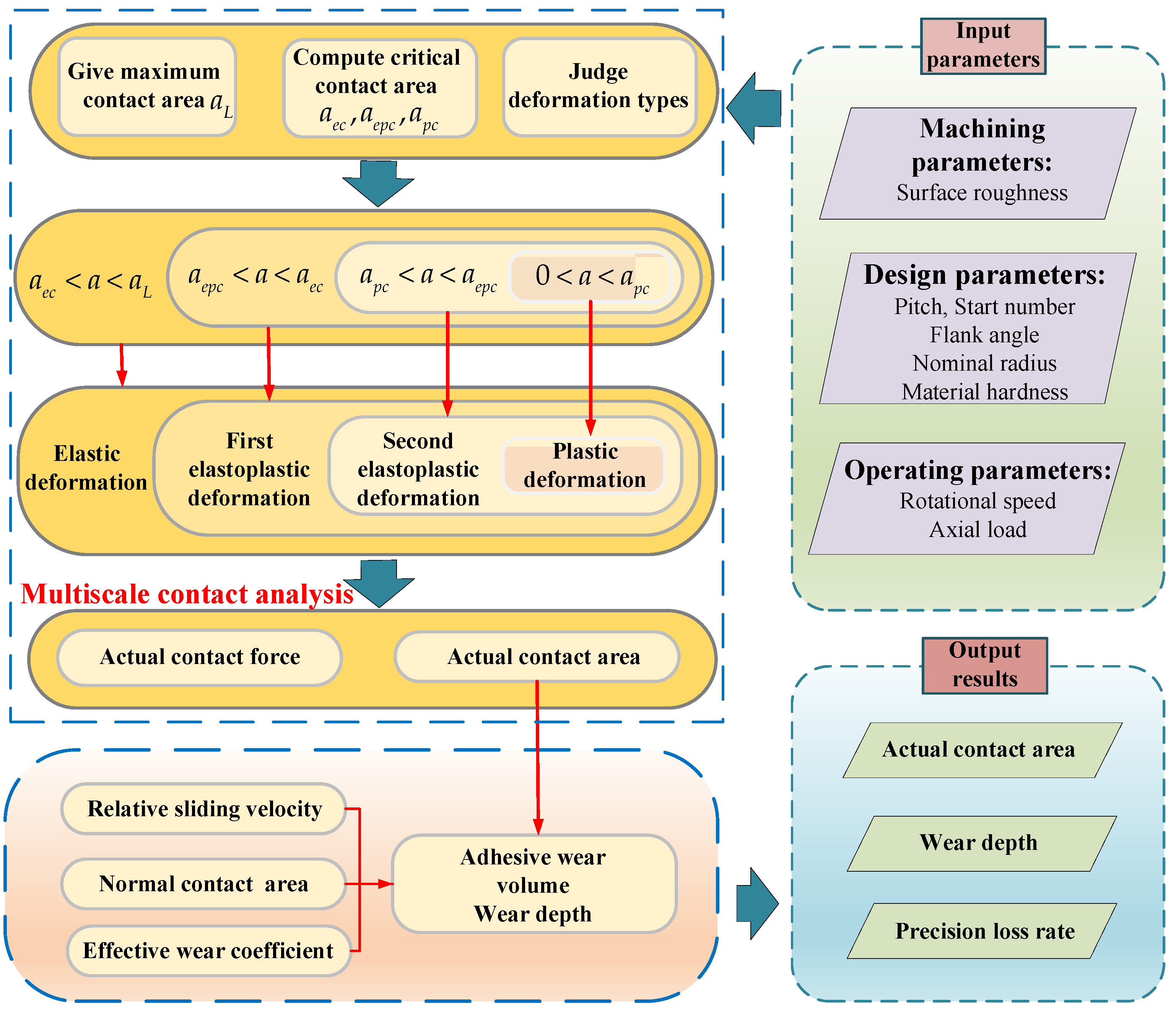
2.6. Numerical Implementation

The overall calculation processing of the actual contact area, wear depth, and precision loss rate is shown in Figure 8, and systematically described as follows:
(1)
Input machining parameters, design parameters and operating conditions;
(2)
Given the maximum contact area of single asperity a L ;
(3)
Calculate the elastic critical contact area aec, elastoplastic critical contact area aepc and plastic contact area apc according to Equations (10) and (11);
(4)
Judge the contact regime. If a L a p c , the microcontact is the fully plastic deformation. If a p c < a L a e p c , the microcontacts include the fully plastic and second elastoplastic deformations. If a e p c < a L a e c , the microcontacts consist of the fully plastic, second elastoplastic and first elastoplastic deformations. If a L > a e c , the microcontacts include the fully plastic, second elastoplastic, first elastoplastic and elastic deformations;
(5)
Compute the total actual contact area and contact force by Equations (21)–(24). If | ( F a F a 0 ) / F a | < ε , then reassign the maximum contact area of single asperity a L = a L + k s Δ a L and jump to step (2) to recalculate the total actual contact force until ε < 0 ;
(6)
Calculate the relative sliding velocity, effective wear coefficient and elliptical contact area according to Equations (30), (33) and (35);
(7)
Compute the wear depth, precision loss and precision loss rate by Equations (34), (37) and (38);
(8)
Output the total actual contact area, wear depth and precision loss rate.

3. Result and Discussion
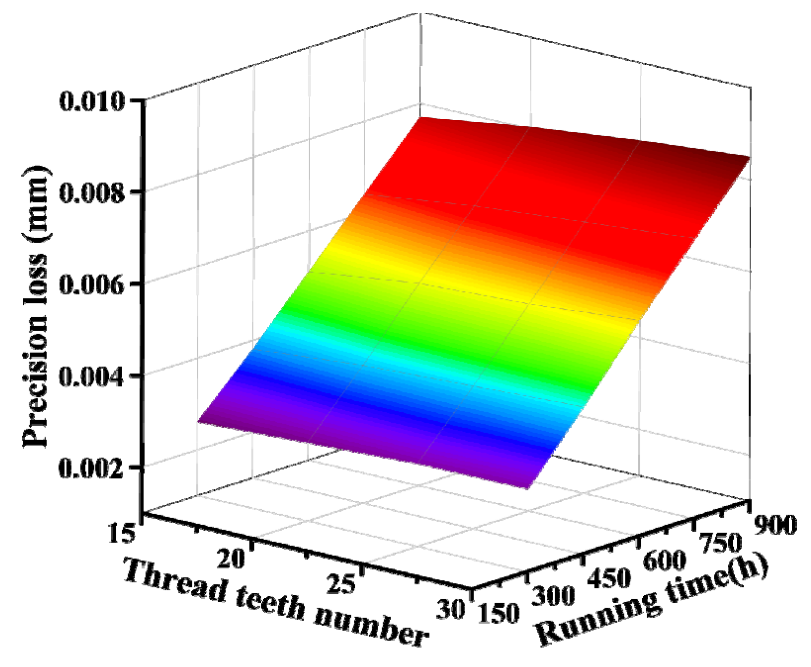
In this section, an investigation on the adhesive wear of the PRSM is carried out by numerical calculations. These results cover total actual contact area, wear depth and precision loss rate by considering the influences of surface roughness, material hardness, material elastic modulus, and axial load. The detailed design parameters of the PRSM are shown in Table 1. The adhesive wear coefficient is approximately 1.69 × 10⁻¹¹ [39].

3.1. Precision Loss

Figure 9 illustrates the variation of the precision loss under the different number of the thread teeth of the roller and running time, when the axial load is 30 kN and the rotational speed is 300 rpm, and the surface roughness is Ra0.3. It can be notably found that the precision loss increases with the growth of the running time. Moreover, the increment of that slowly rises with the increase in the number of the thread teeth of the roller. However, the contact forces of the corresponding thread teeth decrease as the thread teeth number increase [39]. To this end, the increase in wear depth caused by the increase in the number of thread teeth is greater than the decrease in that caused by the decrease in the contact force. It can be concluded that although the increase in the number of the roller thread teeth can reduce the contact forces to a certain extent, it also leads to increased wear of the PRSM and accuracy degradation.

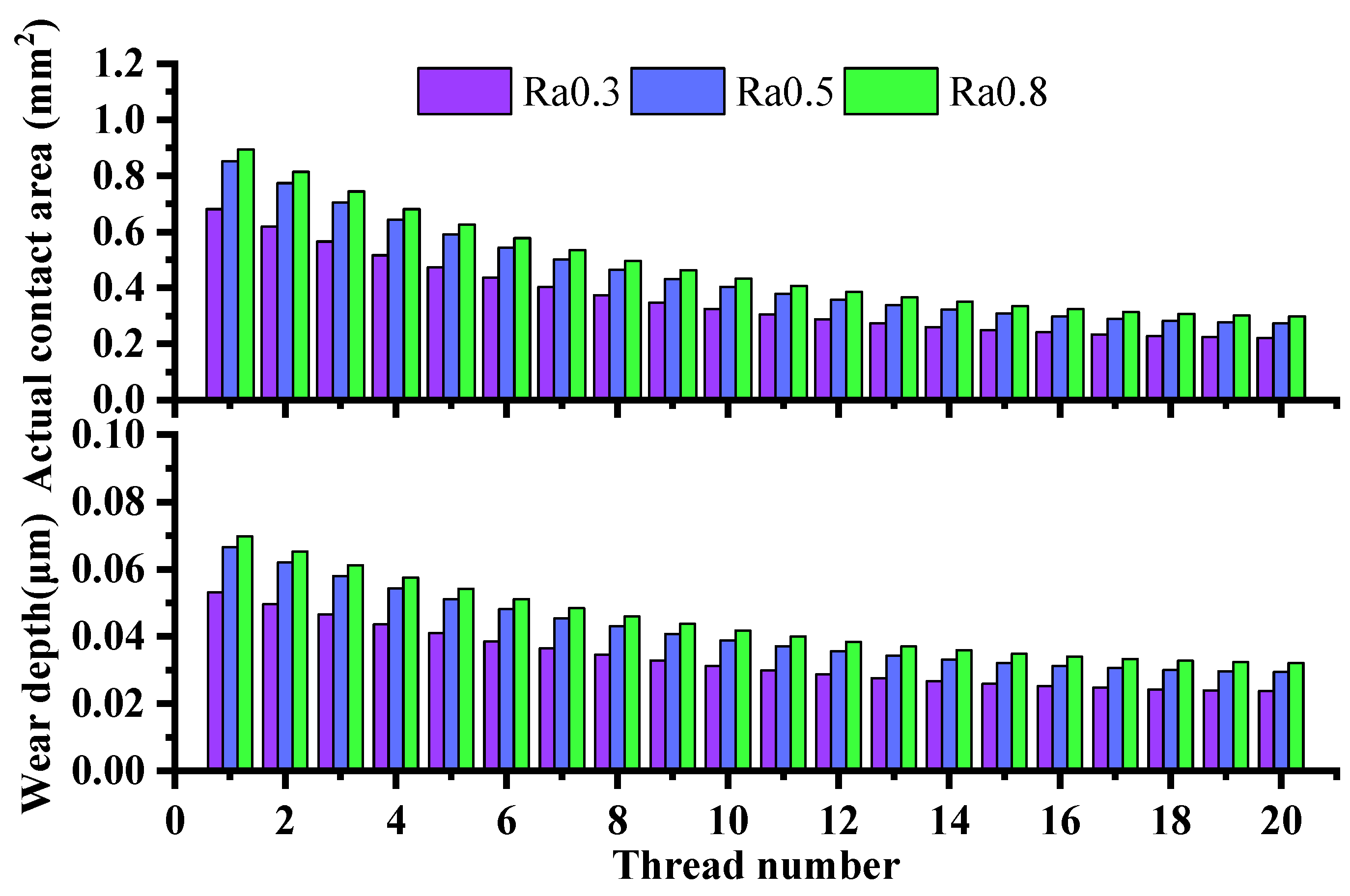
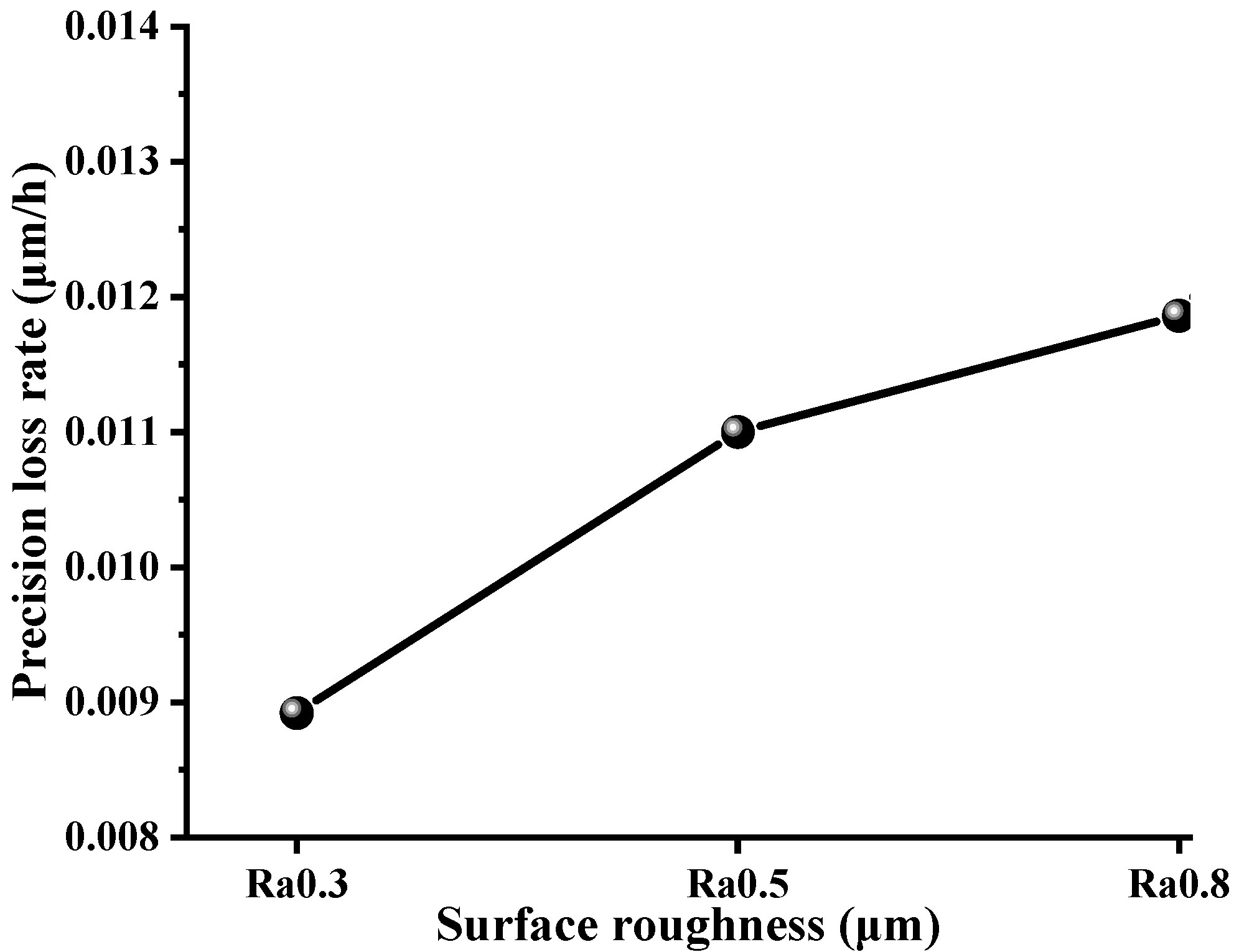
3.2. Effect of Surface Roughness

In order to research the effect of surface roughness on the adhesive wear of the PRSM, the actual contact area, wear depth, and precision loss rate can be estimated according to Section 2. The three-dimension surface topography and two-dimension profile are presented under the different surface roughness (the values are Ra0.3, Ra0.5 and Ra0.8), as shown in Figure 10. These surfaces or profiles are generated by Matlab 2017b with the parameters of Table 2. It can be obviously seen from Figure 10 that the fluctuations between the peak and the valley significantly rise with the increase in surface roughness.
Figure 11 shows the total contact actual area and wear depth at each ellipse with the variations of the surface roughness and thread number, when the axial is 30 kN and the rotational speed is 300 rpm, and the running time is 750 h. As shown in Figure 11, it can be observed that the larger the surface roughness, the bigger the total actual contact area and wear depth at each contact ellipse. The main reason is that the height difference between the highest and the lowest asperities significantly increases with the growth of surface roughness, which causes the increment of the microcontact pressure and plastic deformation of the asperity. That is, under the same contact ellipse and load, the proportion of plastic deformation increases as the roughness increases. As a result, the actual contact area also rises so that the wear depth can increase. That can also be illustrated by Equation (34).
Figure 12 shows the precision loss rate against the surface roughness. It can be seen that the precision loss rate increases with the growth of surface roughness. That is consistent with Figure 11. Therefore, the surface roughness of the thread surface should be as low as possible under the premise of meeting accuracy and cost.

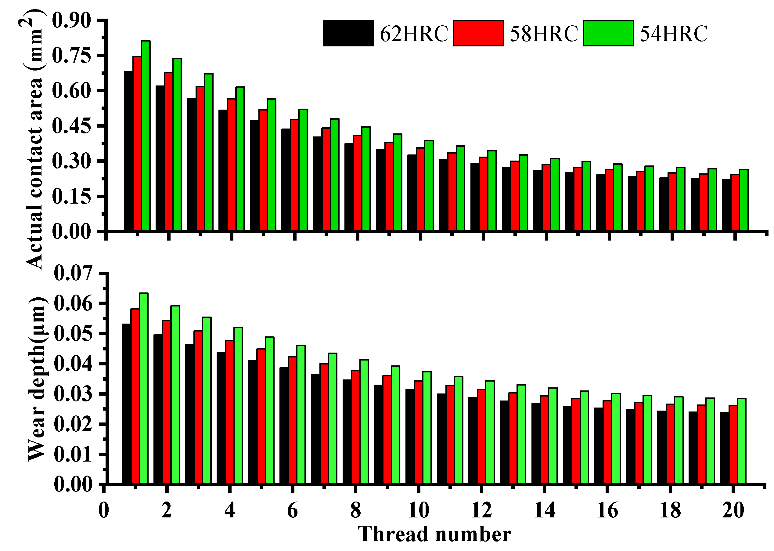
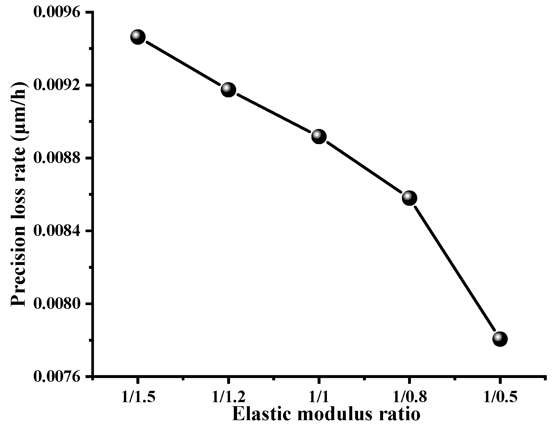
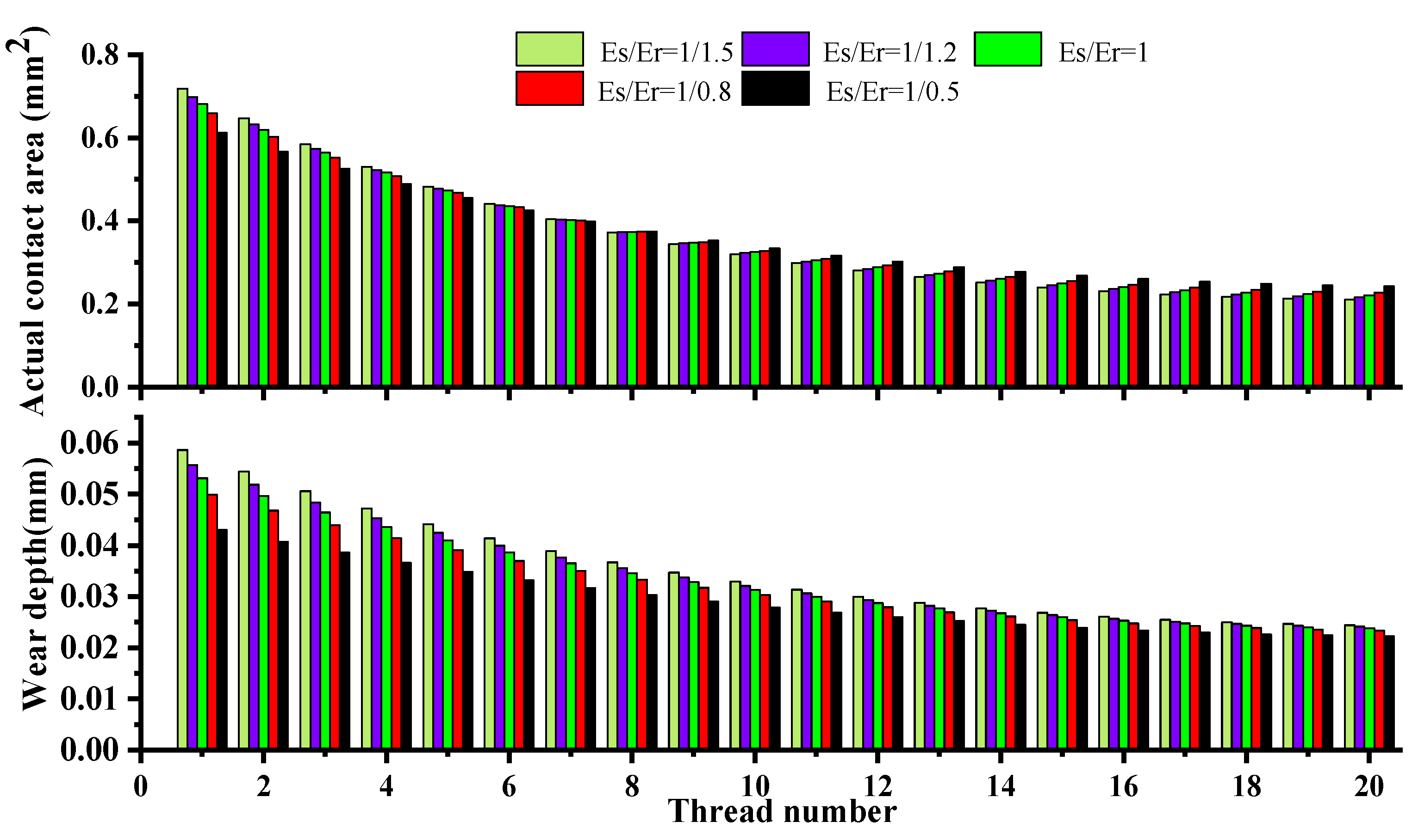
3.3. Effects of Material Hardness and Elastic Modulus Ratio

In the PRSM, the hardness of thread raceway of the screw, roller, and nut is usually 58–62 HRC [40]. Figure 13 shows the variations of total actual contact area and wear depth at each contact ellipse versus the material hardness and thread number, when the axial load is 30 kN, and the surface roughness is Ra0.3, and the rotational speed is 300 rpm. As shown in Figure 13, the total actual area at each ellipse increases with the decrease in material hardness. The main reason is that the higher the hardness of the material, the stronger the surface resistance to plastic deformation. That causes the decrement of total actual contact area at each contact ellipse. The reduction in total actual contact area results in the decrease in the precision loss rate, which is shown in Figure 14. Therefore, it can be concluded that the thread raceway of the screw and roller with high hardness shows better wear resistance and contributes to the precision sustainability to a certain extent.
Figure 15 illustrates the actual contact area and wear depth against the material elastic modulus ratio. It can be markedly found from Figure 15 that the uniformity of the actual contact area distribution increases with the growth of the material elastic modulus ratio Es/Er. The main reason is that the reduction in the elastic modulus of the roller results in an increase in the roller teeth deformation, so that the load distribution can become more uniform. That is similar to bolted joint in [41]. As a result, the distribution of the actual contact area becomes even. Moreover, the wear depth decreases as the increase in the ratio. As can be seen from Figure 16, the results indicate that the precision loss rate reduces by 17.5% from 0.0094 μm/h to 0.0078 μm/h when the elastic modulus ratio varies from 1/1.5 to 1/0.5. Therefore, the elastic modulus of the roller appropriately reduces, especially ensure Es/Er > 1, so that the wear resistance of the PRSM can be effectively improved.

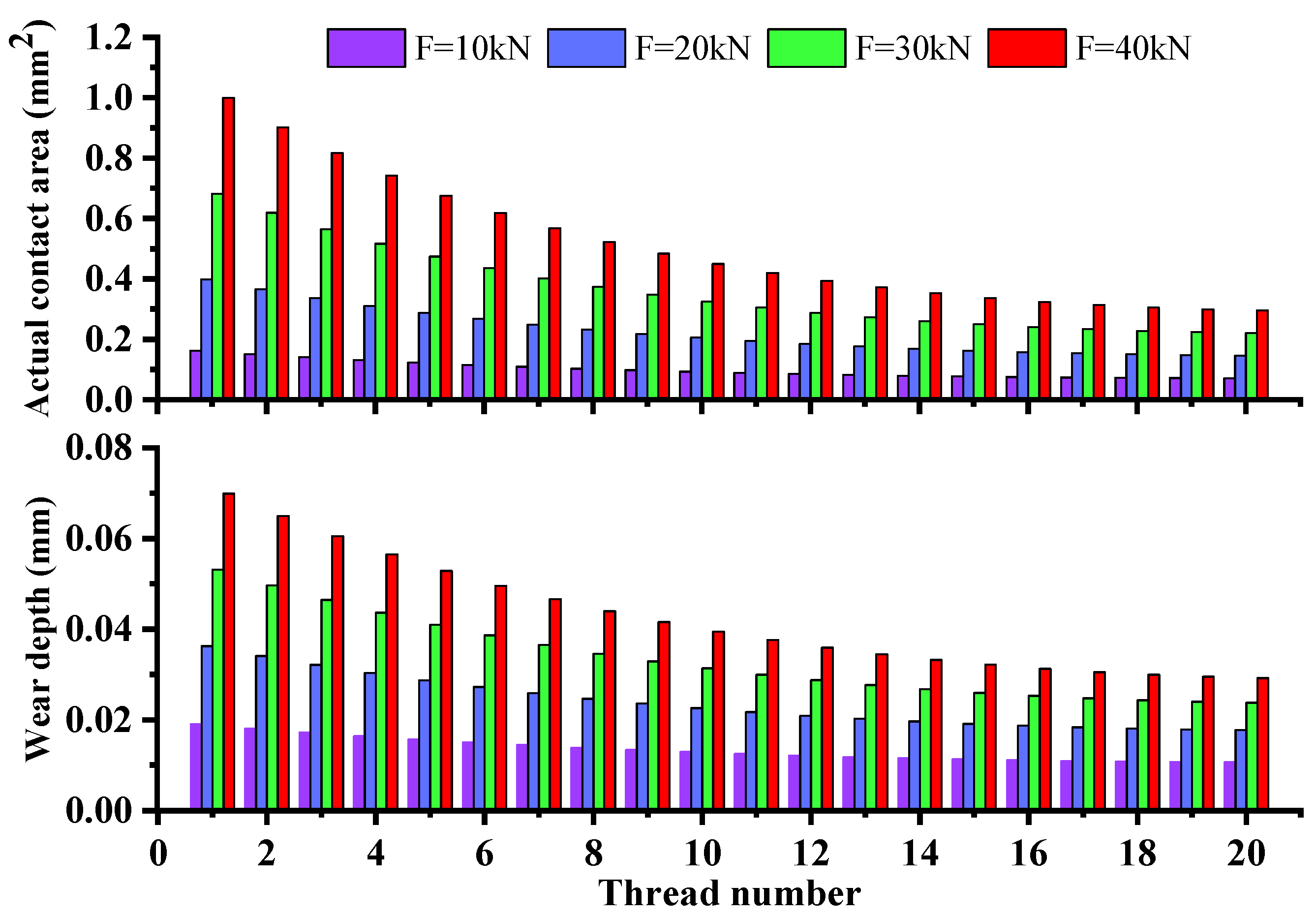
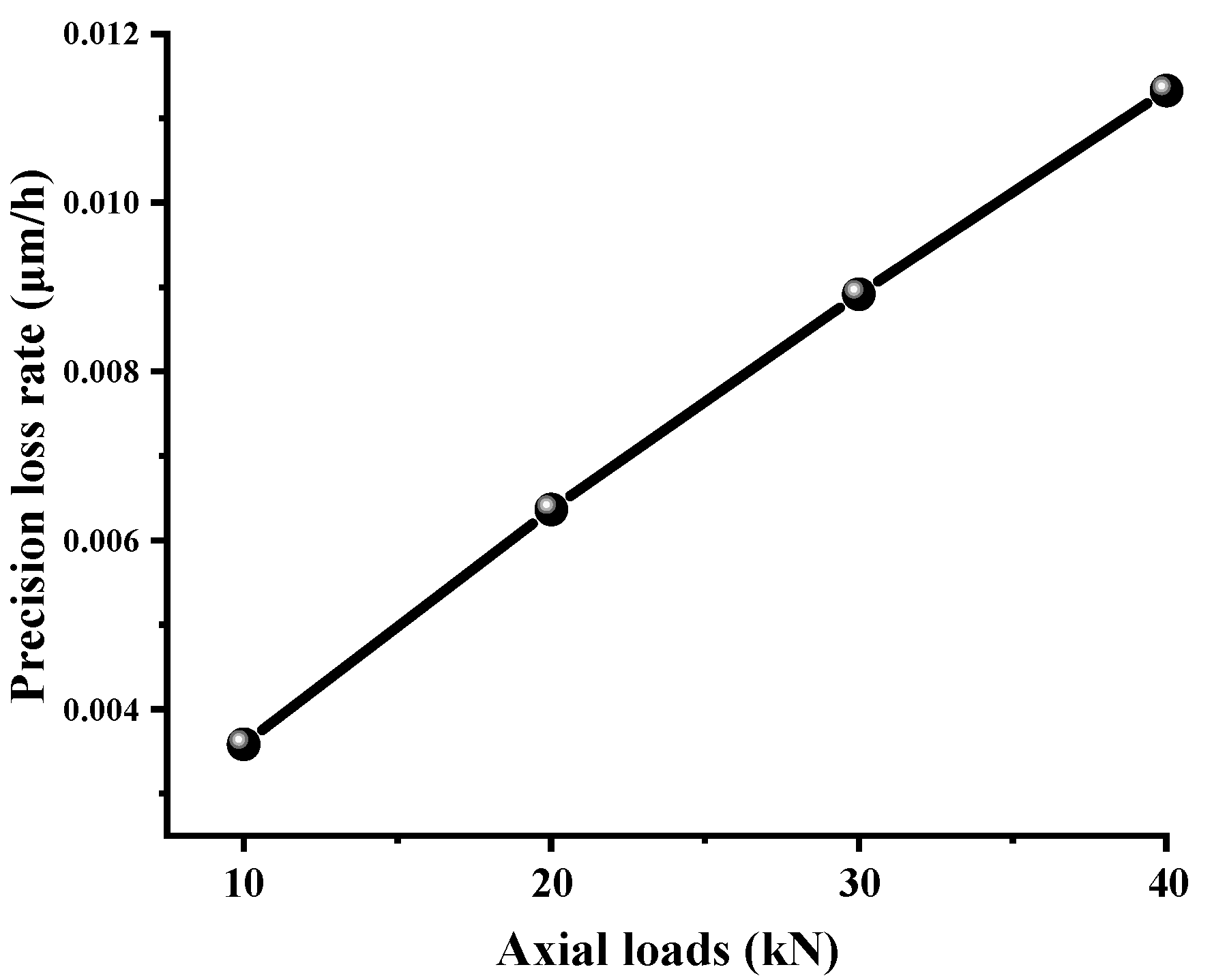
3.4. Effect of Axial Load

Figure 17 illustrates the variations of the total actual contact area and wear depth under the different axial load and thread number, when the rotational speed is 300 rpm and the surface roughness is Ra0.3. It can be found from Figure 17 that the actual contact area at the corresponding thread tooth notably increases with the growth of the axial load. That is mainly due to the fact that, under the same surface roughness, the microcontact forces of the asperities obviously enlarge as an increase in the axial load, which leads to the increment of microcontact deformations. Especially the plastic deformation notably increases at the corresponding height of the asperities. That causes the increment of the plastic contact area so that the wear depth rises accordingly. Moreover, the precision loss rate significantly rises as the increase in axial load shown in Figure 18.

4. Conclusions

In this paper, the adhesive wear mechanism considering the surface roughness of the thread raceway is investigated utilizing Archard’s wear theory and fractal theory. Herein, a multiscale adhesive model is presented by incorporating the surface roughness and material hardness, and modified by combining the effective wear coefficient. The effects of the surface roughness, material hardness, material elastic modulus ratio, and axial load on the actual contact area, wear depth, and precision loss are furtherly studied. The main contributions and conclusions are summarized as follows:
(1)
The surface roughness has a great influence on the wear depth and precision loss. The larger the surface roughness, the higher the height of the asperities at the contact surface, which causes the increment of local plastic microcontacts. That results in the growth of the total actual contact area. As a result, the wear depth and precision loss rate significantly increase;
(2)
The influence of the material hardness on the variation of the precision loss rate is obvious. The higher the hardness of the material, the stronger the surface resistance to plastic deformation. That causes the decrement of total actual contact area at each contact ellipse so that the precision loss rate can be notably decreased;
(3)
The increase in the material elastic modulus ratio ( E s / E r ) will improve the uniformity of the actual contact area distribution and load distribution. The precision loss rate is reduced accordingly. The suggested material elastic modulus ratio is more than 1 with comprehensive consideration of the contact deformation mechanism and axial load;
(4)
The accuracy degradation of the PRSM considering the rough surface is also influenced by the working conditions. When the axial load rises, the actual contact area and contact force become larger, so the wear depth and precision loss become aggravated accordingly.

Author Contributions

J.M.: conceptualization, investigation, software, writing—original draft. X.D.: conceptualization, methodology, project administration, supervision, writing—review and editing. Y.L.: investigation, software, validation. P.C.: formal analysis, supervision. F.X. and L.W.: validation. All authors have read and agreed to the published version of the manuscript.

Funding

This research was funded by the National Key Research & Development Program of China (Grant No. 2017YFB1300700).

Institutional Review Board Statement

Not applicable.

Informed Consent Statement

Not applicable.

Data Availability Statement

The data that support the findings of this study are available from the authors upon reasonable request.

Conflicts of Interest

The authors declare no conflict of interest.

Nomenclature

a , a Real contact area and truncated contact area, respectively, (m2)
a e , b e Ellipse semi-major and semi-minor axes, respectively, (m)
a L Maximum contact area, (m2)
m a Major semi-axis coefficient of the contact ellipse
n Number of the roller
n t Number of the thread teeth of the roller
q Spatial frequency index
r , r Actual contact radius and truncated radius of the asperity, respectively, (m)
v 1 , v 2 Poisson ratio of the screw and roller, respectively
A a Nominal contact area, (m2)
A r Total actual contact area at single contact ellipse, (m2)
D , D 3 Fractal dimension of the two-dimensional profile and three-dimensional topography, respectively
E 1 , E 2 Young’s modulus of the screw and the roller, respectively, (Pa)
F a , F a 1 Total axial load and single roller axial load, respectively, (N)
F r i Normal contact force at ith contact ellipse, (N)
G Fractal roughness, (m)
K w , K w E Archard’s wear coefficient and effective wear coefficient, respectively
L Sample length, (m)
M Number of superimposed ridges
S Relative sliding distance (m)
Greek letters
λ r Helix angle of the roller, (rad)
δ Contact deformation of single asperity, (m)
ψ Domain extension factor
ρCurvature sum
Subscript
e c Critical elastic contact
e p c Critical elastoplastic contact
p c Critical plastic contact
e Elastic contact
e p 1 First elastoplastic contact
e p 2 Second elastoplastic contact
p Plastic contact
Superscript
* Dimensionless variable
Truncated variable

References

  1. Maré, J.-C.; Fu, J. Review on signal-by-wire and power-by-wire actuation for more electric aircraft. Chin. J. Aeronaut. 2017, 30, 857–870. [Google Scholar] [CrossRef]
  2. Liu, J.; Ma, C.; Wang, S. Precision loss modeling method of ball screw pair. Mech. Syst. Signal Process. 2020, 135, 106397. [Google Scholar] [CrossRef]
  3. Jones, M.H.; Velinsky, S.A. Contact Kinematics in the Roller Screw Mechanism. J. Mech. Design. 2013, 135, 051003. [Google Scholar] [CrossRef]
  4. Liu, Y.; Wang, J.; Cheng, H.; Sun, Y. Kinematics Analysis of the Roller Screw Based on the Accuracy of Meshing Point Calculation. Math. Probl. Eng. 2015, 2015, 303972. [Google Scholar] [CrossRef] [Green Version]
  5. Hojjat, Y.; Mahdi Agheli, M. A comprehensive study on capabilities and limitations of roller–screw with emphasis on slip tendency. Mech. Mach. Theory 2009, 44, 1887–1899. [Google Scholar] [CrossRef]
  6. Zhang, W.; Liu, G.; Tong, R.; Ma, S. Load distribution of planetary roller screw mechanism and its improvement approach. Proc. Inst. Mech. Eng. Part C J. Mech. Eng. Sci. 2016, 230, 3304–3318. [Google Scholar] [CrossRef]
  7. Ma, S.; Wu, L.; Liu, G.; Fu, X. Local contact characteristics of threaded surfaces in a planetary roller screw mechanism. Mech. Based Des. Struct. Mach. 2020, 48, 1–26. [Google Scholar] [CrossRef]
  8. Zhang, W.; Liu, G.; Ma, S.; Tong, R. Load distribution over threads of planetary roller screw mechanism with pitch deviation. Proc. Inst. Mech. Eng. Part C J. Mech. Eng. Sci. 2019, 233, 4653–4666. [Google Scholar] [CrossRef]
  9. Jones, M.H.; Velinsky, S.A.; Lasky, T.A. Dynamics of the Planetary Roller Screw Mechanism. J. Mech. Robot. 2015, 8, 014503. [Google Scholar] [CrossRef]
  10. Fu, X.; Liu, G.; Tong, R.; Ma, S.; Lim, T.C. A nonlinear six degrees of freedom dynamic model of planetary roller screw mechanism. Mech. Mach. Theory 2018, 119, 22–36. [Google Scholar] [CrossRef]
  11. Sandu, S.; Biboulet, N.; Nelias, D.; Abevi, F. An efficient method for analyzing the roller screw thread geometry. Mech. Mach. Theory 2018, 126, 243–264. [Google Scholar] [CrossRef]
  12. Sandu, S.; Biboulet, N.; Nelias, D.; Abevi, F. Analytical prediction of the geometry of contact ellipses and kinematics in a roller screw versus experimental results. Mech. Mach. Theory 2019, 131, 115–136. [Google Scholar] [CrossRef]
  13. Fu, X.; Liu, G.; Ma, S.; Tong, R.; Lim, T.C. A Comprehensive Contact Analysis of Planetary Roller Screw Mechanism. J. Mech. Des. 2017, 139, 012302. [Google Scholar] [CrossRef]
  14. Jones, M.H.; Velinsky, S.A. Kinematics of roller migration in the planetary roller screw mechanism. J. Mech. Des. Trans. ASME 2012, 134, 061006. [Google Scholar] [CrossRef]
  15. Du, X.; Chen, B.; Zheng, Z. Investigation on mechanical behavior of planetary roller screw mechanism with the effects of external loads and machining errors. Tribol. Int. 2021, 154, 106689. [Google Scholar] [CrossRef]
  16. Ma, S.; Wu, L.; Fu, X.; Li, Y.; Liu, G. Modelling of static contact with friction of threaded surfaces in a planetary roller screw mechanism. Mech. Mach. Theory 2019, 139, 212–236. [Google Scholar] [CrossRef]
  17. Xie, Z.; Xue, Q.; Wu, J.; Gu, L.; Wang, L.; Song, B. Mixed-lubrication analysis of planetary roller screw. Tribol. Int. 2019, 140, 105883. [Google Scholar] [CrossRef]
  18. Fu, X.; Liu, G.; Ma, S.; Tong, R.; Li, X. An efficient method for the dynamic analysis of planetary roller screw mechanism. Mech. Mach. Theory 2020, 150, 103851. [Google Scholar] [CrossRef]
  19. Aurégan, G.; Fridrici, V.; Kapsa, P.; Rodrigues, F. Experimental simulation of rolling–sliding contact for application to planetary roller screw mechanism. Wear 2015, 332–333, 1176–1184. [Google Scholar] [CrossRef]
  20. Auregan, G.; Fridrici, V.; Kapsa, P.; Rodrigues, F. Wear Behavior of Martensitic Stainless Steel in Rolling-Sliding Contact for Planetary Roller Screw Mechanism: Study of the WC/C Solution. Tribol. Online 2016, 11, 209–217. [Google Scholar] [CrossRef] [Green Version]
  21. Molinari, J.-F.; Aghababaei, R.; Brink, T.; Frérot, L.; Milanese, E. Adhesive wear mechanisms uncovered by atomistic simulations. Friction 2018, 6, 245–259. [Google Scholar] [CrossRef] [Green Version]
  22. Seo, J.-W.; Jun, H.-K.; Kwon, S.-J.; Lee, D.-H. Rolling contact fatigue and wear of two different rail steels under rolling–sliding contact. Int. J. Fatigue 2016, 83, 184–194. [Google Scholar] [CrossRef]
  23. Li, G.; Wang, Z.H.; Zhu, W.D. Prediction of Surface Wear of Involute Gears Based on a Modified Fractal Method. J. Tribol. 2018, 141, 031603. [Google Scholar] [CrossRef]
  24. Xu, C.; Wu, T.; Huo, Y.; Yang, H. In-situ characterization of three dimensional worn surface under sliding-rolling contact. Wear 2019, 426–427, 1781–1787. [Google Scholar] [CrossRef]
  25. Zhang, X.; Xu, Y.; Jackson, R.L. A mixed lubrication analysis of a thrust bearing with fractal rough surfaces. Proc. Inst. Mech. Eng. Part J J. Eng. Tribol. 2020, 234, 608–621. [Google Scholar] [CrossRef]
  26. Tan, Y.; Zhang, L.; Hu, Y. A Wear Model of Plane Sliding Pairs Based on Fatigue Contact Analysis of Asperities. Tribol. T. 2015, 58, 148–157. [Google Scholar] [CrossRef]
  27. Wang, S.; Komvopoulos, K. A Fractal Theory of the Interfacial Temperature Distribution in the Slow Sliding Regime: Part I—Elastic Contact and Heat Transfer Analysis. J. Tribol. 1994, 116, 812–822. [Google Scholar] [CrossRef]
  28. Wang, S.; Komvopoulos, K. A Fractal Theory of the Interfacial Temperature Distribution in the Slow Sliding Regime: Part II—Multiple Domains, Elastoplastic Contacts and Applications. J. Tribol. 1994, 116, 824–832. [Google Scholar] [CrossRef]
  29. Yan, W.; Komvopoulos, K. Contact analysis of elastic-plastic fractal surfaces. J. Appl. Phys. 1998, 84, 3617–3624. [Google Scholar] [CrossRef]
  30. Sahoo, P.; Roy Chowdhury, S.K. A fractal analysis of adhesive wear at the contact between rough solids. Wear 2002, 253, 924–934. [Google Scholar] [CrossRef]
  31. Yin, X.; Komvopoulos, K. An adhesive wear model of fractal surfaces in normal contact. Int. J. Solids Struct. 2010, 47, 912–921. [Google Scholar] [CrossRef] [Green Version]
  32. Wang, R.; Zhu, L.; Zhu, C. Research on fractal model of normal contact stiffness for mechanical joint considering asperity interaction. Int. J. Mech. Sci. 2017, 134, 357–369. [Google Scholar] [CrossRef]
  33. Wang, Z.; Zhou, Q. Applying a population growth model to simulate wear of rough surfaces during running-in. Wear 2012, 294–295, 356–363. [Google Scholar] [CrossRef]
  34. Gong, Z.Q.; Komvopoulos, K. Thermomechanical Analysis of Semi-Infinite Solid in Sliding Contact With a Fractal Surface. J. Tribol. 2005, 127, 331–342. [Google Scholar] [CrossRef]
  35. Milanese, E.; Brink, T.; Aghababaei, R.; Molinari, J.-F. Emergence of self-affine surfaces during adhesive wear. Nat. Commun. 2019, 10, 1116. [Google Scholar] [CrossRef] [Green Version]
  36. Majumdar, A.; Bhushan, B. Role of Fractal Geometry in Roughness Characterization and Contact Mechanics of Surfaces. J. Tribol. 1990, 112, 205–216. [Google Scholar] [CrossRef]
  37. Huang, K.; Xiong, Y.; Wang, T.; Chen, Q. Research on the dynamic response of high-contact-ratio spur gears influenced by surface roughness under EHL condition. Appl. Surf. Sci. 2017, 392, 8–18. [Google Scholar] [CrossRef]
  38. You, J.M.; Chen, T.N. A static friction model for the contact of fractal surfaces. Proc. Inst. Mech. Eng. Part J J. Eng. Tribol. 2010, 224, 513–518. [Google Scholar] [CrossRef]
  39. Ma, S.; Liu, G.; Fu, X.; Zhang, W.; Qiao, G. Load distribution of rollers considering errors in planetary roller screw mechanism. J. Harbin Inst. Technol. 2015, 47, 98–102. [Google Scholar]
  40. EWELLIX Roller Screws. Available online: https://www.ewellix.com/en/mr/products/ball-and-roller-screws/roller-screws (accessed on 10 November 2021).
  41. Chen, H.; Zeng, P.; Fang, G.; Lei, Y. Load Distribution of Bolted Joint. Chin. J. Mech. Eng. 2010, 46, 171–178. [Google Scholar] [CrossRef]
Figure 1. Planetary roller screw mechanism.
Fractalfract 05 00237 g001
Figure 2. The technical diagram of multiscale wear evaluation of the PRSM.
Fractalfract 05 00237 g002
Figure 3. Interfacial topography measurement.
Fractalfract 05 00237 g003
Figure 4. Schematic diagram of single asperity contact.
Fractalfract 05 00237 g004
Figure 5. Microcontact deformation of single asperity.
Fractalfract 05 00237 g005
Figure 6. Velocity analysis at the screw–roller interface.
Fractalfract 05 00237 g006
Figure 7. Wear and contact mechanism at the screw–roller interface.
Fractalfract 05 00237 g007
Figure 8. Flowchart of the calculation of the wear volume and precision loss.
Fractalfract 05 00237 g008
Figure 9. The variation of the precision loss versus the number of thread teeth of the roller and running time.
Fractalfract 05 00237 g009
Figure 10. Three-dimension fractal surfaces and two-dimension rough profiles under the different surface roughness: (a1,a2) are Ra0.3; (b1,b2) are Ra0.5; (c1,c2) are Ra0.8.
Fractalfract 05 00237 g010
Figure 11. The variations of the total contact area and wear depth versus the surface roughness and thread number.
Fractalfract 05 00237 g011
Figure 12. Precision loss rate in different surface roughness.
Fractalfract 05 00237 g012
Figure 13. The variations of the total contact area and wear depth versus the material hardness and thread number.
Fractalfract 05 00237 g013
Figure 14. Precision loss rate under different material hardness.
Fractalfract 05 00237 g014
Figure 15. The variations of the total actual contact area and wear depth versus the material elastic modulus ratio and thread number.
Fractalfract 05 00237 g015
Figure 16. Precision loss rate under different material elastic modulus ratio.
Fractalfract 05 00237 g016
Figure 17. Actual contact area in different axial loads.
Fractalfract 05 00237 g017
Figure 18. Precision loss rate in different axial loads.
Fractalfract 05 00237 g018
Table 1. The design parameters of the PRSM.
ParametersScrewRollerNut
Radius (mm)10.53.517.5
Flank angle (rad)π/4π/4π/4
Pitch (mm)222
Start515
Roller number/10/
Teeth number1202020
MaterialGCr15
Hardness (HRC)62
Poisson ratio0.29
Table 2. The fractal surface parameters.
Surface RoughnessRa0.3Ra0.5Ra0.8
Fractal dimension D1.6071.5731.542
Fractal roughness G/m2.93 × 10−93.84 × 10−95.43 × 10−9
Sample length L/μm500500500
Publisher’s Note: MDPI stays neutral with regard to jurisdictional claims in published maps and institutional affiliations.

