Article

CMOS OTA-Based Filters for Designing Fractional-Order Chaotic Oscillators

by
Martín Alejandro Valencia-Ponce
1,†,
Perla Rubí Castañeda-Aviña
1,†,
Esteban Tlelo-Cuautle
1,†,
Victor Hugo Carbajal-Gómez
2,†,
Victor Rodolfo González-Díaz
2,†,
Yuma Sandoval-Ibarra
3,† and
Jose-Cruz Nuñez-Perez
4,*,†
1
Department of Electronics, Instituto Nacional de Astrofísica, Optica y Electrónica (INAOE), Luis Enrique Erro No. 1, Tonantzintla, Puebla 72840, Mexico
2
Faculty of Electronics Sciences, Autonomous University of Puebla (BUAP), Av. San Claudio y 18 Sur, Edif. FCE2, Puebla 72570, Mexico
3
Departamento de Posgrado, Universidad Politécnica de Lázaro Cárdenas (UPLC), Lázaro Cárdenas 60950, Mexico
4
Instituto Politécnico Nacional, IPN-CITEDI, Tijuana 22435, Mexico
*
Author to whom correspondence should be addressed.
These authors contributed equally to this work.
Fractal Fract. 2021, 5(3), 122; https://doi.org/10.3390/fractalfract5030122
Submission received: 24 August 2021 / Revised: 9 September 2021 / Accepted: 10 September 2021 / Published: 14 September 2021
(This article belongs to the Special Issue Fractional-Order Circuit Theory and Applications)

Abstract

:
Fractional-order chaotic oscillators (FOCOs) have shown more complexity than integer-order chaotic ones. However, the majority of electronic implementations were performed using embedded systems; compared to analog implementations, they require huge hardware resources to approximate the solution of the fractional-order derivatives. In this manner, we propose the design of FOCOs using fractional-order integrators based on operational transconductance amplifiers (OTAs). The case study shows the implementation of FOCOs by cascading first-order OTA-based filters designed with complementary metal-oxide-semiconductor (CMOS) technology. The OTAs have programmable transconductance, and the robustness of the fractional-order integrator is verified by performing process, voltage and temperature variations as well as Monte Carlo analyses for a CMOS technology of 180 nm from the United Microelectronics Corporation. Finally, it is highlighted that post-layout simulations are in good agreement with the simulations of the mathematical model of the FOCO.

1. Introduction

It is well known that chaotic systems can occur in various natural and man-made systems, and are known to have great sensitivity to initial conditions. On the one hand, as already mentioned in [1], according to the Poincaré–Bendixson theorem, autonomous and integer-order chaotic oscillators must have a minimum order of three for chaos to appear. The three ordinary differential equations (ODEs) can be associated to state variables that can be designed with complementary metal-oxide-semiconductor (CMOS) integrated circuit (IC) technology, as was done in [2], from three decades ago. On the other hand, fractional-order chaotic oscillators (FOCOs) do not follow the integer-order characteristic in which the number of state variables define the order. For example, if a FOCO is modeled by three ODEs and each derivate has a fractional-order equal to 0.9, then the fractional-order of the system is 2.7.
In the time domain, the majority of FOCOs can be simulated by applying approximations, such as Grüwnwald–Letnikov [3], Adams–Bashforth–Moulton and Adomian decompositions [4,5]. Those algorithms were implemented using embedded systems, such as field-programmable gate arrays (FPGAs), but compared to analog solutions, they require huge hardware resources. For example, field-programmable analog arrays (FPAAs) and amplifiers were used to design FOCOs in [3,6], and fractional-order circuits were also implemented by a constant phase element, as shown in [7]. The authors in [8] showed cryptographic applications of a FOCO with high-effective analog computation, using amplifiers and two anti-parallel semiconductor diodes to provide a hyperbolic sine nonlinearity.
Some examples of the analog and digital implementations of commensurate (all derivatives have the same fractional order) or incommensurate (all or some derivatives have different fractional order) FOCOs are given in [3]. In the analog domain, and from a state-space point of view, the fractional-order derivative is solved by implementing a fractional-order integrator that can be designed using discrete amplifiers or FPAAs. The fractional-order integrator can be synthesized by fractances, fractal capacitors or other fractional-order topologies, as summarized in [3,9]. However, recently, the authors in [10] showed approximations of the fractional-order differentiator and integrator operators, using standard active filter transfer functions. Some CMOS realizations were validated via simulations, using CMOS technology of 350nm. More recently, a new category of fractional-order filters, realized without employing a fractional-order Laplacian operator, was introduced in [11], where the procedure resulted in a rational integer-order transfer function, and its implementation was possible, using conventional integer-order realization techniques. This is the focus of this work, following the design of FOCOs by cascading active filters, as shown in [12].
The operational amplifier (opamp) is the universal device used to implement chaotic systems [13], and hyper-chaotic [14], and multi-scroll attractors [15]. The voltage level of opamp-based implementations of FOCOs can be scaled down to allow FPAA implementations [12] but still, the silicon area is huge. In this manner, and as already demonstrated in [2], the CMOS operational transconductance amplifier (OTA) is helpful to reduce the silicon area when designing chaotic systems. Other CMOS amplifiers that are useful to design chaotic oscillators are summarized in [16], and others include the following: voltage differencing transconductance amplifier (VDTA) [17], current backward transconductance amplifier (CBTA) [18], operational trans-resistance amplifier (OTRA) [19], second-generation current conveyor (CCII), differential-input double-output transconductance amplifier (DOTA+), and differential voltage current conveyor (DVCC) [20]. Among them, the OTA shows advantages to develop cryptographic applications [21].
An incommensurate fractional-order Rössler system was implemented, using CMOS OTAs in [22]. The CMOS OTA was also used to design the fractional-order Newton–Leipnik chaotic system [23], and fractional-order neuron models [24,25]. In this manner, we show the CMOS OTA-based design of a fractional-order integrator that is approximated by a Laplace transfer function, as shown in [1]. The transfer function is synthesized herein by designing CMOS OTA-based first-order active filters, and the robustness of the CMOS FOCOs is verified by performing process, voltage and temperature (PVT) variations as well as Monte Carlo (MC) analyses [26]. The design of FOCOs using CMOS technology will improve applications in lightweight security [27], low-power and wireless secure communications [3], and Internet of Things [28].
The rest of this paper is organized as follows: Two FOCOs are the case study and are described in Section 2. Their block diagram descriptions in the Laplace domain and our proposed OTA implementations of the fractional-order integrator and FOCOs are shown in Section 3. Section 4 shows the design of OTAs, multiplier, saturated nonlinear function, and fractional-order integrator, using CMOS technology of 180 nm from the United Microelectronics Corporation (UMC). The layout design and post-layout simulations are given in Section 5, along with PVT and MC analyses to guarantee the robustness of the OTA-based CMOS FOCOs. Finally, the conclusions are given in Section 6.

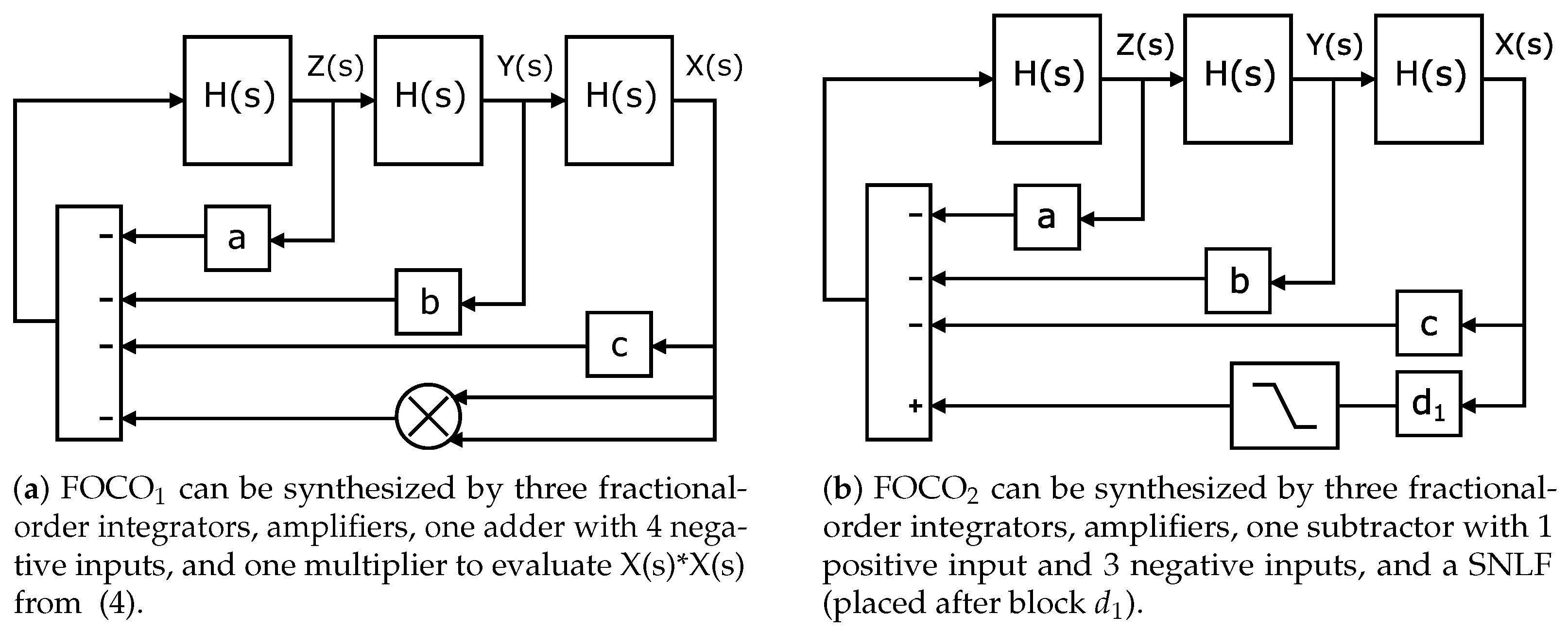
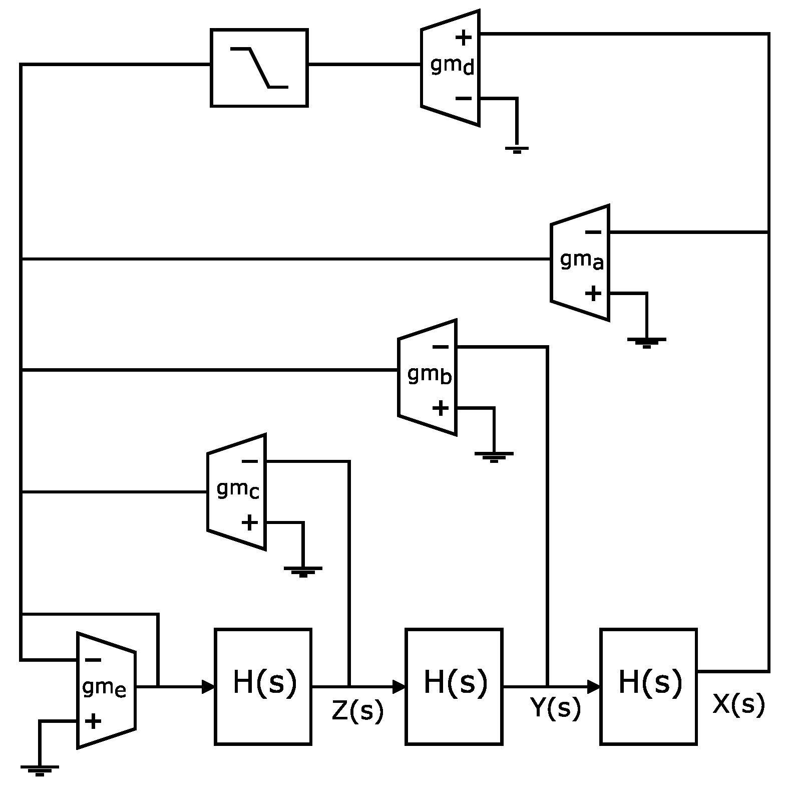
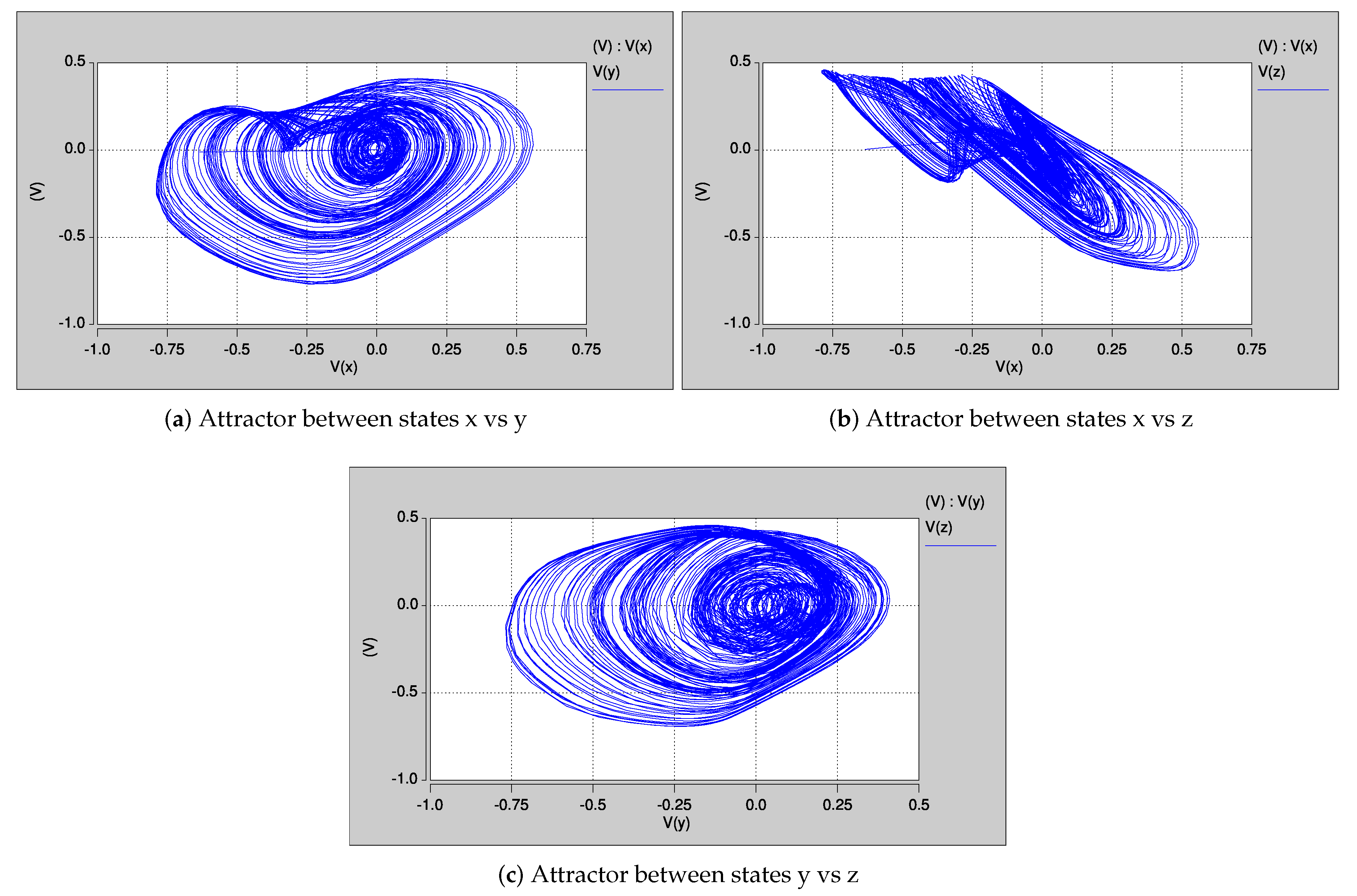
2. Fractional-Order Chaotic Oscillators

Nowadays, fractional calculus is widely applied in many engineering areas; one of them was highlighted in the topic of fractional-order circuits and systems [3,9], where the main goal is the approximation of the fractional-order differentiator and integrator operators [10,11,12]. As emphasized in [29], the main advantage of fractional calculus is to extend the differential operators such that they exhibit non-integers orders. For instance, according to the Riemann–Liouville approach, the notion of a fractional integral of order α ( α > 0 ) is a natural consequence of the Cauchy formula defined in (1) for repeated integrals [30], where the gamma function is given in (2). Introducing the Laplace transform by the notation L { f ( t ) } = 0 e s t f ( t ) d t to (2), one can obtain (3), which is a generalization of the case with n-fold repeated integrals ( α = n ) .
0 I t α f ( t ) 1 Γ ( α ) 0 t ( t τ ) α 1 f ( τ ) d τ
Γ ( α ) 0 e t t α 1 d t
L { 0 I t α f ( t ) } = 1 s α L { f ( t ) }
Taking advantage of the Laplace transform, this section describes two representative FOCOs that are labeled as FOCO 1 and FOCO 2 . FOCO 1 is taken from [31]; its scaled model in the Laplace domain, to allow the CMOS design, is given in (4), and it consists of three state variables: X ( s ) , Y ( s ) , and Z ( s ) , and one quadratic term x 2 . From these equations, it can be appreciated that its implementation requires amplifiers, adders, subtractors, and one multiplier to design the quadratic term. The derivatives have a fractional order equal to 0.9, and it generates chaotic behavior by setting a = 2.05 , b = 1.12 , and c = 0.42 , and using initial conditions equal to x 0 = 0.1 , y 0 = z 0 = 0 . Figure 1 shows the portraits of FOCO 1 , which are obtained by plotting the state variables among them to appreciate the chaotic attractor.
s 0.9 X ( s ) = Y ( s ) s 0.9 Y ( s ) = Z ( s ) s 0.9 Z ( s ) = a X ( s ) b Y ( s ) c Z ( s ) 3 X ( s ) X ( s )
The second case study FOCO 2 has three derivatives of fractional-order 0.9 [32], and its model is given in (5). It consists of three state variables— X ( s ) , Y ( s ) , and Z ( s ) —and a nonlinear function denoted by f ( x ) that can be approximated by saturated nonlinear function (SNLF) series. From (5), one can observe that the design requires amplifiers, adders, and subtractors, and the SNLF is manipulated to generate multi-scroll attractors. For example, a two-scroll attractor can be implemented by modeling the SNLF by (6), where m is the slope of the linear segment in the ranges b p x b p , with b p as a break-point, and the saturation level is given by k. It is simulated by setting a = b = c = d 1 = 0.7, m = k / b p = 0.5 / 0.1 for f ( x ) , and initial conditions x 0 = y 0 = z 0 = 0.1 . Figure 2 shows the portraits of FOCO 2 , which are obtained by plotting the state variables among them to appreciate the chaotic attractor.
s 0.9 X ( s ) = Y ( s ) s 0.9 Y ( s ) = Z ( s ) s 0.9 Z ( s ) = a X ( s ) b Y ( s ) c Z ( s ) + d 1 f ( x )
f ( x ) = k if x < b p m x if b p x b p k if x > b p
The amplitudes of the state variables of both FOCOs are lower than ±1, so they are suitable to be implemented with CMOS technology of 180 nm from UMC, which is biased by ±0.9 V.

3. Approximation of the Fractional-Order Integrator by OTA Filters

According to [1,3], the fractional-order integrator can be approximated by H ( s ) = 1 / s 0.9 , and therefore, Figure 3 shows the block diagrams of FOCO 1 and FOCO 2 . In this paper, the fractional-order is set to 0.9, whose approximated transfer function is given in (7) [1]. The design of OTA-based active filter topologies can be performed by using first-order functions, as already shown in [33]. Henceforth, the transfer function of a fractional-order integrator H ( s ) can be arranged to multiply first-order functions as given in (8). As one sees, H 1 ( s ) and H 2 ( s ) have one zero and one pole, and can be designed with first-order shelving equalizers, while H 3 ( s ) can be designed by one low-pass filter.
H ( s ) = 1 s 0.9 2.2675 ( s + 1.292 ) ( s + 215.4 ) ( s + 0.01292 ) ( s + 2.154 ) ( s + 359.4 )
c H 1 ( s ) = s + 215.4 s + 359.4 H 2 ( s ) = s + 1.292 s + 2.154 H 3 ( s ) = 2.2675 s + 0.01292
The first-order active filters are designed with the OTA-based topologies shown in Figure 4. As highlighted in [33], the shelving equalizer can independently adjust the pole and zero, and the transfer function from Figure 4a is given in (9), while that for the low-pass filter shown in Figure 4b is given in (10).
V o u t V i n = s + g m 1 / C s + g m 2 / C
V o u t V i n = g m 1 / C s + g m 2 / C
From (9) and H 1 ( s ) , one can choose the value of g m 1 to evaluate C and the resistance generated by g m 2 . Therefore, if g m 1 = 500 μ A/V the capacitor value is obtained as C = g m 1 215.4 = 2.32 μ F. In this manner, g m 2 = ( 2.32 μ F ) ( 359.4 ) = 833 μ A/V. The same process is performed to evaluate all the transconductances of the OTAs and Cs associated to H 2 ( s ) and H 3 ( s ) . For H 2 ( s ) , g m 1 = 500 μ A/V, C = 386 μ F, and g m 2 = 833 μ A/V. For H 3 ( s ) , g m 1 = 500 μ A/V, C = 221 μ F, and g m 2 = 2.93 μ A/V.
Our proposed OTA implementation of the fractional-order integrator is shown in Figure 5, where it is worth mentioning that the three first-order OTA filters are connected in cascade, considering that the filter with the largest zero and largest pole is placed at the input port, i.e., H 1 ( s ) .
The OTAs can be macro-modeled into the simulation program with IC emphasis (SPICE). That way, from Figure 3a our proposed OTA implementation of FOCO 1 is shown in Figure 6, where H ( s ) is designed as shown in Figure 5. The HSPICE simulation of FOCO 1 is done by setting the transconductance values as follows: g m a to g m h are obtained to accomplish the values of the coefficients a = 2.05 , b = 1.12 and c = 0.42 given in (4). For instance, if g m 1 = 500 μ A/V, then g m a must be 2.05 times g m 1 . The same process is performed to obtain all the transconductance values so that g m a = 1025 μ A/V, g m b = 560 μ A/V, g m c = 210 μ A/V and g m g = 3000 μ A/V. g m h = 500 μ A/V, and is used to transform the sum of the output currents of each OTA into voltage.
The multiplier is implemented with the macro-model AD734. The simulation results of our proposed OTA-based FOCO 1 are shown in Figure 7.
From Figure 3b, our proposed OTA implementation of FOCO 2 is shown in Figure 8, where H ( s ) is designed as shown in Figure 5. The HSPICE simulation of FOCO 2 is done by setting g m a = 350 μ A/V, g m b = 350 μ A/V, g m c = 350 μ A/V, g m d = 350 μ A/V and g m e = 1000 μ A/V. The SNLF block is macro-modeled by a piecewise-linear (PWL) function with breakpoints b p = 0.1 and k = 0.5 . The simulation results of the OTA-based FOCO 2 are shown in Figure 9.

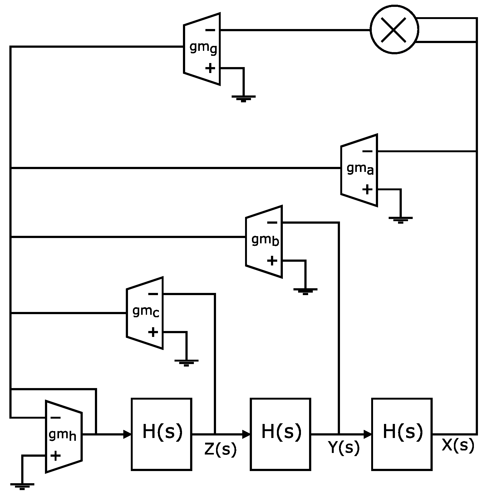
4. CMOS Design of the OTAs, Multiplier, Nonlinear Function and Fractional-Order Integrator

The CMOS design of FOCOs becomes a challenge, due to the high level of accuracy required to accomplish the characteristics of the OTAs, the fractional-order integrator and nonlinear functions to create the attractor. For instance, the OTAs require high differential gain, high gain-bandwidth product, and the best linearity as possible [34]. In addition, an OTA must be robust to PVT and Monte Carlo variations [35]. This section details the design of the blocks required to implement the proposed OTA-based FOCO 1 shown in Figure 6 and FOCO 2 shown in Figure 8, by using CMOS technology of 180 nm from UMC.

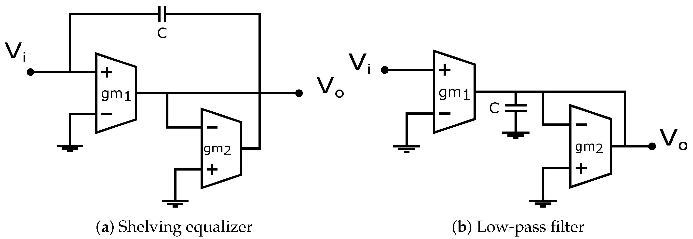
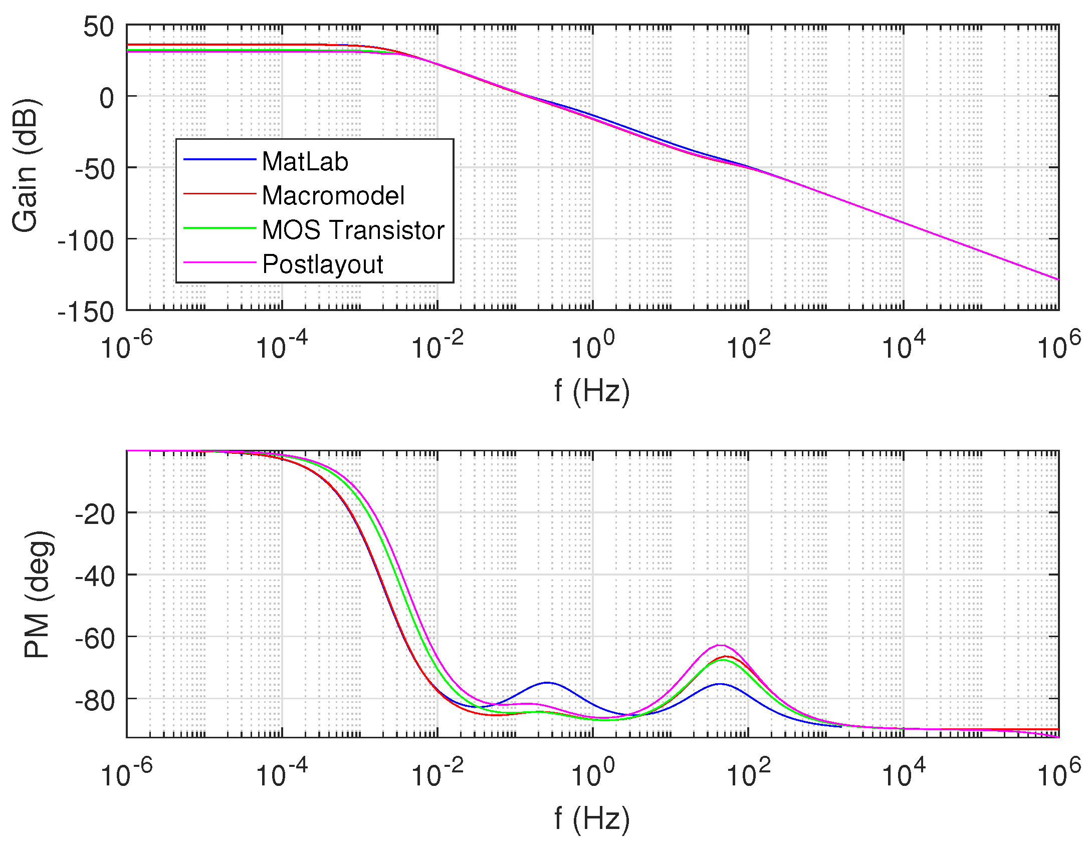
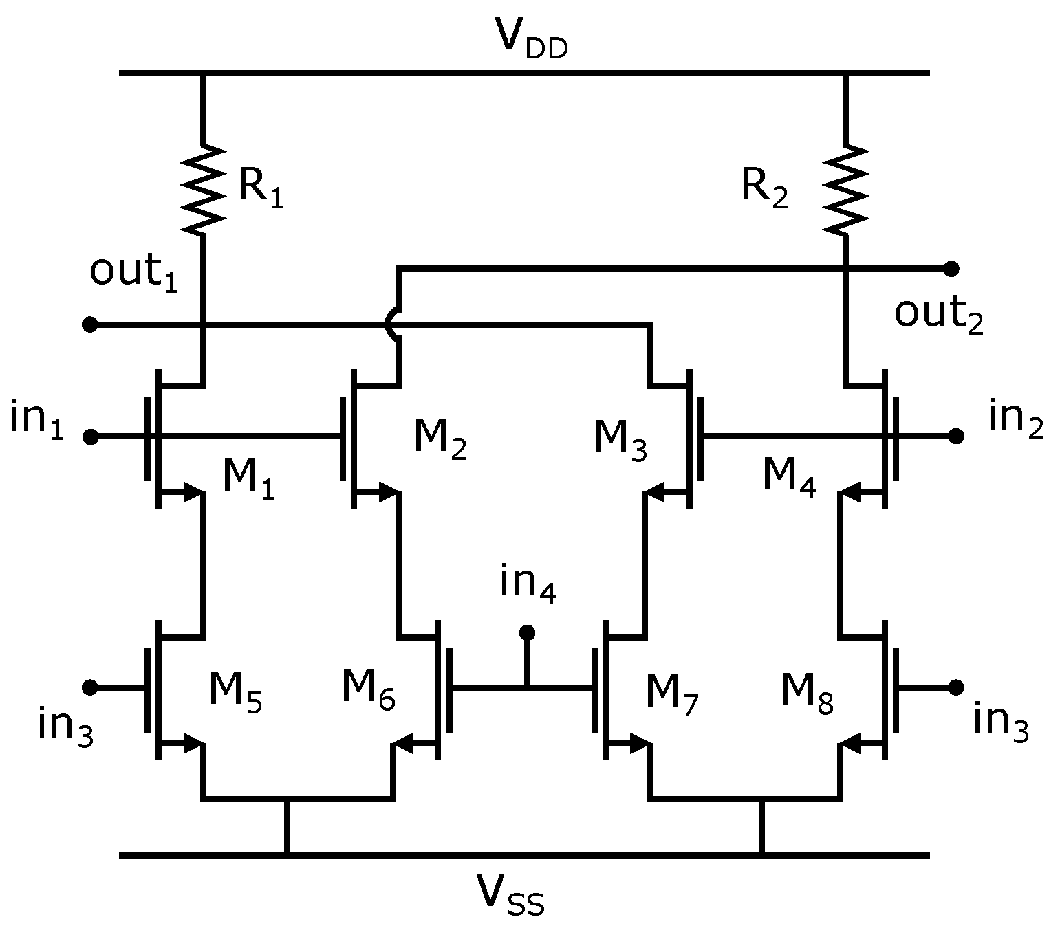
4.1. CMOS Operational Transconductance Amplifier (OTA)

The OTA that is required to implement a FOCO must provide high linearity to accomplish the characteristics of the fractional-order integrator. A slight variation in the linearity may generate a fractional-order different from the desired one, and the response of the FOCO may be mitigated or be different from the desired one. The linearity of the OTA is characterized by its transconductance g m , which must be linear in the entire dynamic range.
As for the FOCO 1 the transconductances have values between 210 μ A/V and 3000 μ A/V, and since the range in which the g m of an OTA can be varied with the variable resistors is only ±150 μ A/V, then the variable resistors are mainly used to improve the accuracy of the OTA. For this reason, this paper uses different sizes of the transistors and the OTA with programmable g m shown in Figure 10, where the transconductance is tuned by the resistors R connected in the sources of the differential pair. The Rs can be designed with MOS transistors, as detailed in [36], and the bias of the flipped voltage-followers are designed according to [37]. The sizes of the CMOS OTA, to provide a g m = 500 μ A/V and g m = 350 μ A/V, are shown in Table 1 by using a load capacitor of C L = 220 pF. The table lists the direct current (DC) gain in decibels (dB), gain-bandwidth (GBW) in kilo hertz (KHz), phase margin (PM) in degrees ( ), common-mode rejection ration (CMRR) in dB, slew rate (SR) in volt/ μ s, power supply rejection ratio (PSRR), power dissipation in milliwatts, the small and large-signal figures of merit (FoM) from [35], the width (W) and length (L) of the MOS transistors in micro-meters, and the bias current (Ib).
To design both FOCOs, other transconductances ( g m ) are required. Table 1 shows the sizes of the MOS transistors of two g m values, but for the complete design, seven g m values are required, namely, 2 μ A/V, 200 μ A/V, 350 μ A/V, 500 μ A/V, 800 μ A/V, 1000 μ A/V, and 3000 μ A/V. These g m s are obtained by designing the CMOS OTA with different bias currents and voltage controls of the degenerated resistors that are implemented by MOS transistors as shown in [36].

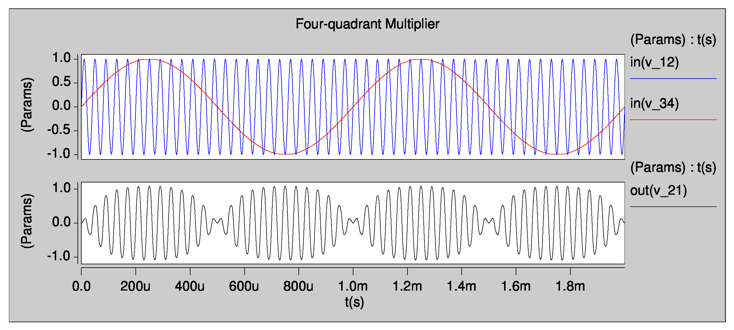
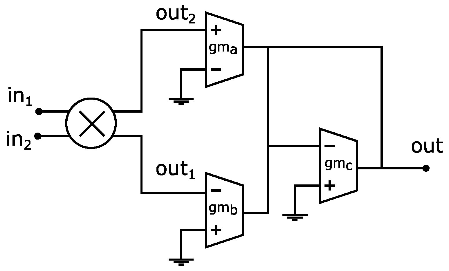
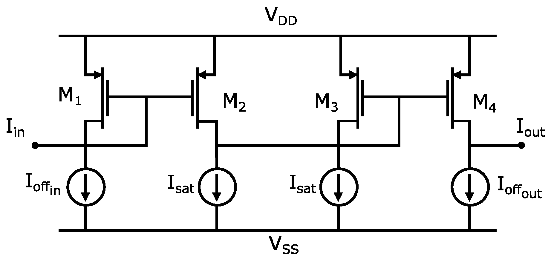
4.2. CMOS Multiplier Design

To evaluate X(s)*X(s) in Figure 6, the CMOS multiplier is designed by using the topology shown in Figure 11. This CMOS circuit is a four-quadrant multiplier in which both the input and output signals fluctuate among positive and negative values, and it was introduced in [38].
The sizes of the MOS transistors are found by considering that they are operating in the saturation region, as shown in [35]. The W/L ratios of all the MOS transistors from M 1 to M 8 are equal to 1.44 μ m/0.18 μ m. The resistance values are calculated to be R 1 = R 2 = 3 k Ω . The CMOS multiplier was tested with sinusoidal waveforms connected in the differential inputs ( V i n 1 V i n 2 ) and ( V i n 3 V i n 4 ) , with the differential output taken as ( V o u t 2 V o u t 1 ) . The multiplication result is shown in Figure 12. This is worth mentioning since a single-ended output is needed in Figure 6. Then, we propose the addition of an OTA subtractor, as shown in Figure 13, to provide V o u t = V o u t 2 V o u t 1 , where g m a = g m b = g m c = 500 μ A/V.

4.3. Saturated Nonlinear Function (SNLF) Design

In the case of FOCO 2 , it requires a SNLF block to design the PWL function shown in Figure 3b, which has three linear segments. This SNLF can be designed by the CMOS topology shown in Figure 14, which was proposed in [36]. This CMOS circuit presents advantages, such as programmability of the slope m, saturation level k, and break-points b p required in (6). The sizes of the MOS transistors are W = 1.35 μ m for M 1 , M 2 , M 3 , W = 6.3 μ m for M 4 , and all the lengths are set to L = 0.18 μ m.

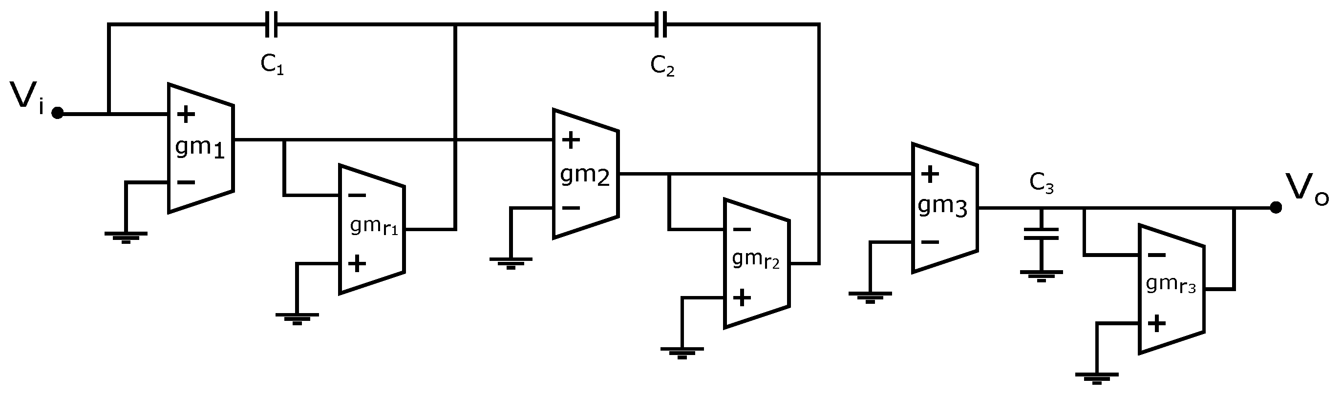
4.4. Proposed CMOS Fractional-Order Integrator

As shown in Figure 5, our proposed OTA design of the fractional-order integrator 1 / s 0.9 needs the design of the CMOS OTAs, whose transconductances are set to 500 μ A/V, 800 μ A/V and 2 μ A/V. Table 1 shows the sizes of the OTA to provide a g m = 500 μ A/V, and Table 2 and Table 3 show the W / L sizes of the OTAs to provide transconductances of 800 μ A/V and 2 μ A/V, respectively. The multiplicity value is necessary to design the layout, as shown in [35,36].

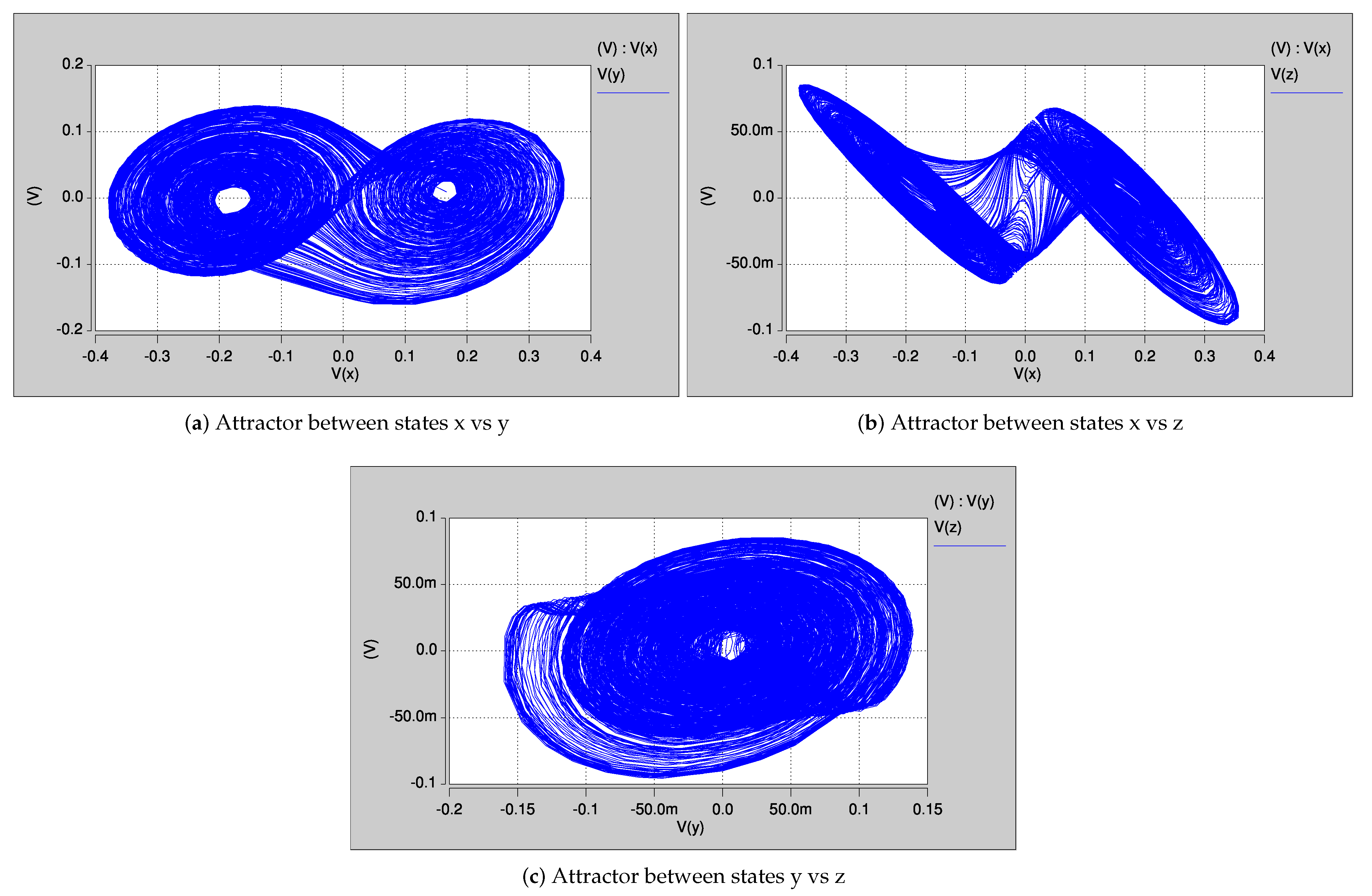
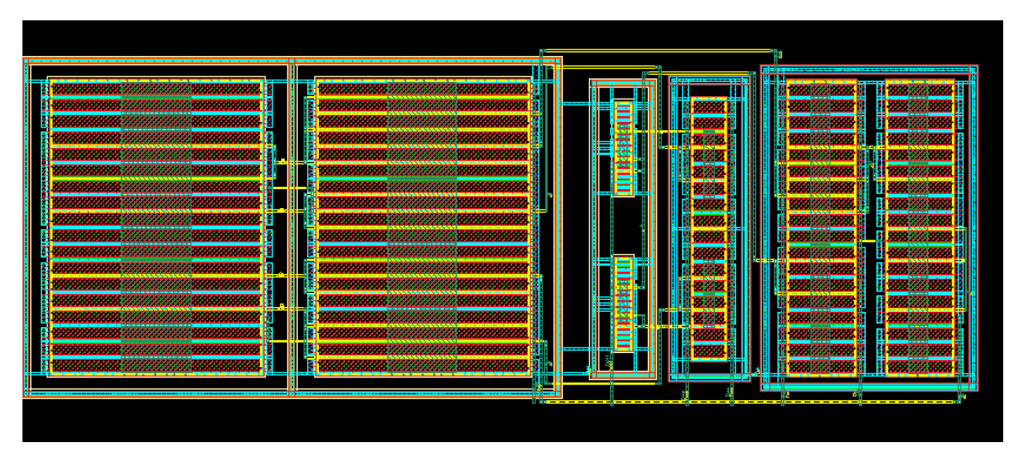
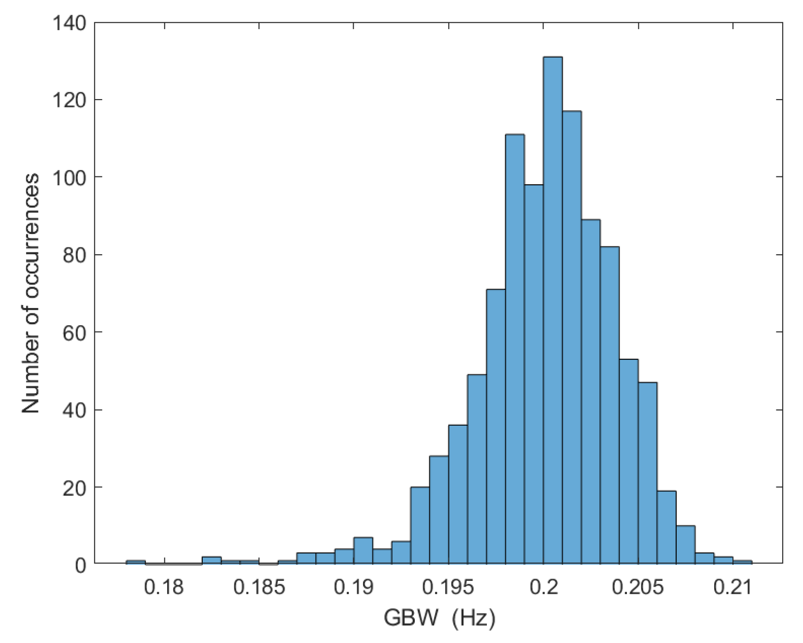
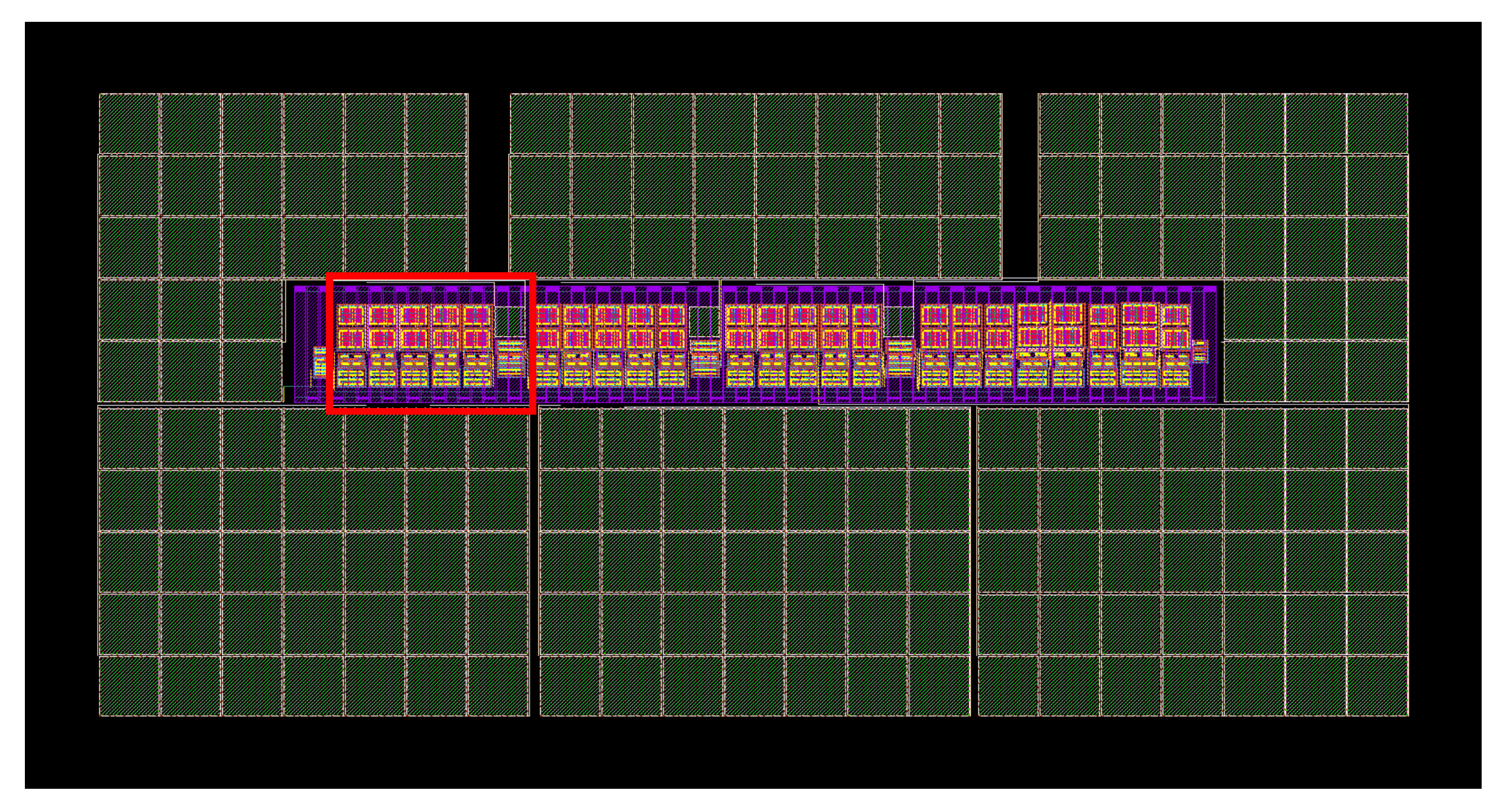
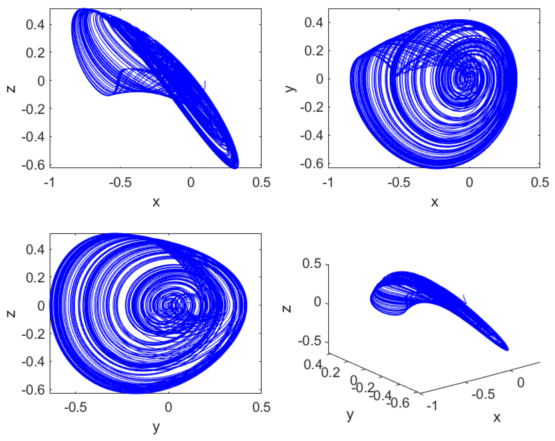
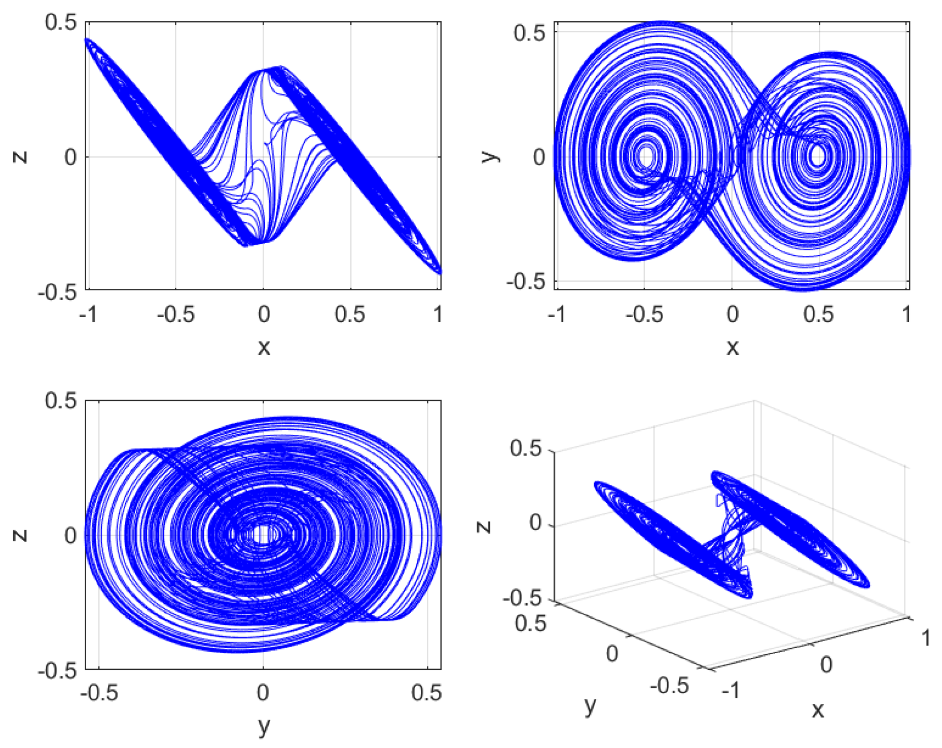
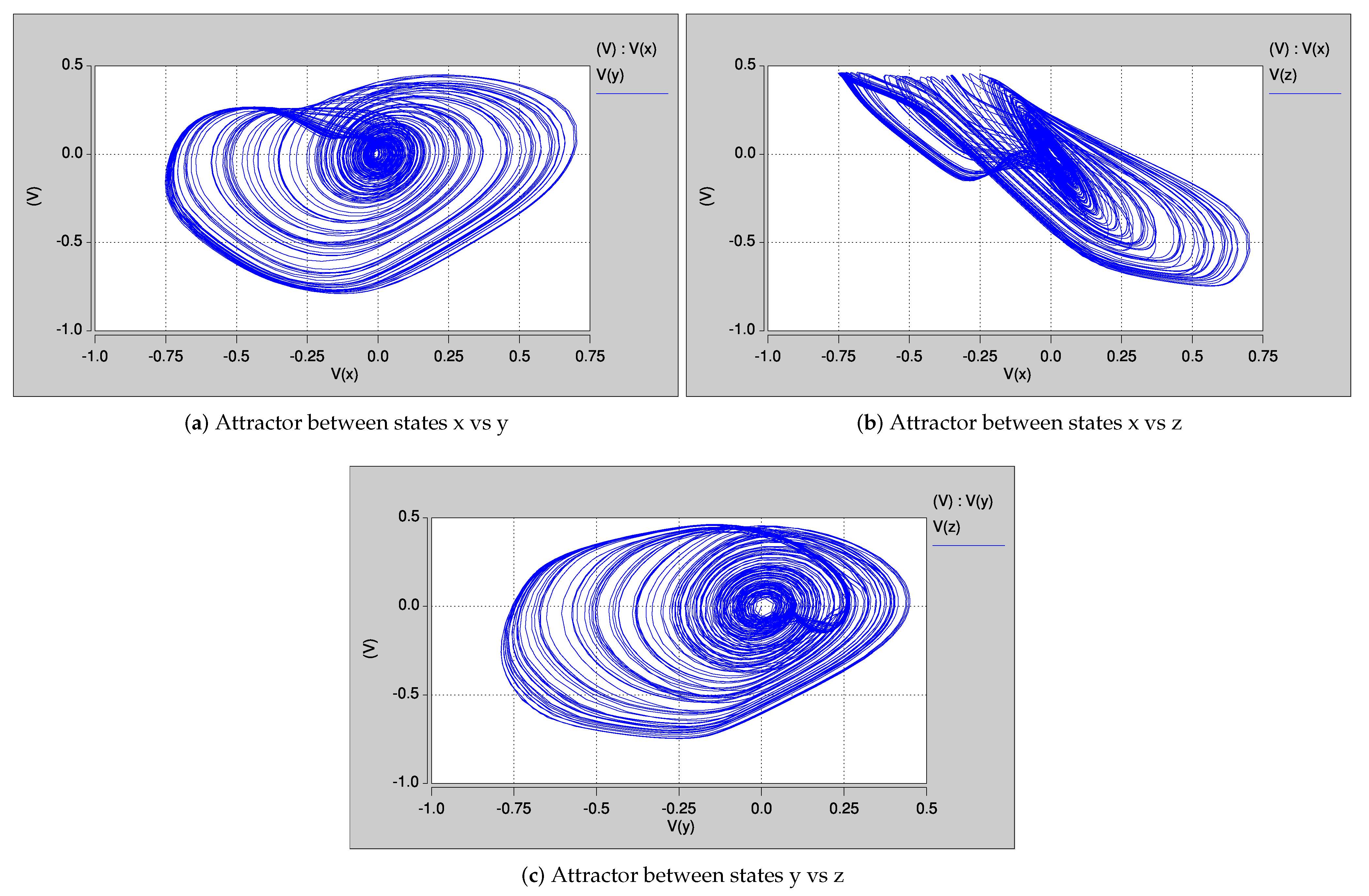
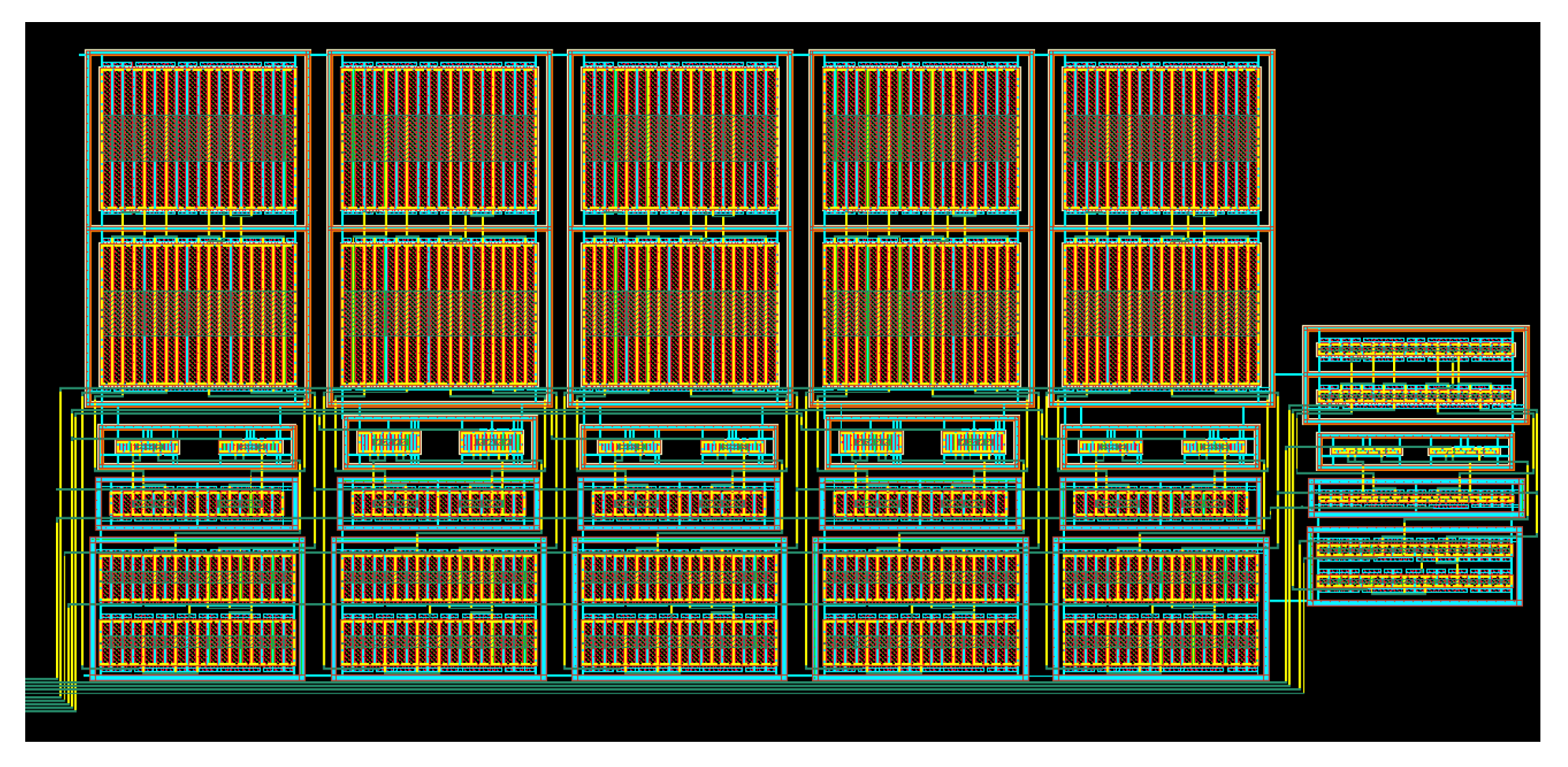
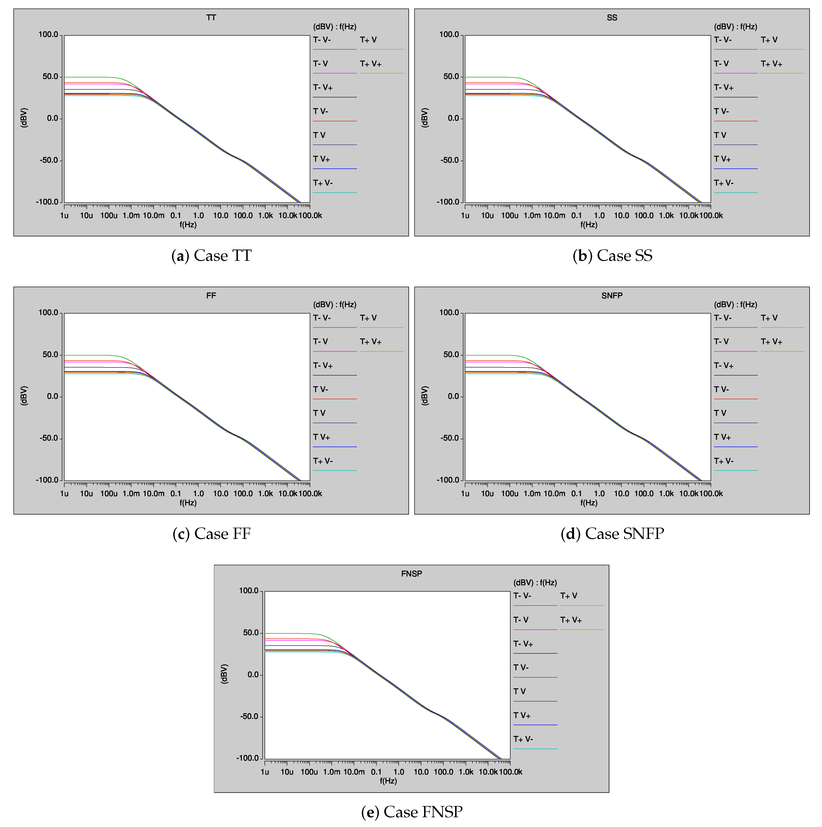
5. Layout Design and Post-Layout Simulation Results

The layout of the OTA with a g m = 500 μ A/V is shown in Figure 15, which considers electromigration and symmetry, and a maximum height is determined for the final layout to implement the FOCOs in a reduced silicon area. The other OTAs, having different g m values, are designed in a similar manner. So, the layout of our proposed OTA-based fractional-order integrator is shown Figure 16, which consists of six OTAs (see Figure 5): three OTAs having g m = 500 μ A/V, two OTAs of g m = 800 μ A/V and the last and smallest (on the right side) having g m = 2 μ A/V. The capacitors are set to: C 1 = 2.5 μ F, C 2 = 380 μ F and C 3 = 220 μ F.
The post-layout simulation of our proposed CMOS fractional-order integrator H ( s ) = 1 / s 0.9 , has very low error compared to the ideal transfer function in the MatLab-evaluation from (7), compared to the OTA macro-model simulation from Figure 5, and compared to the HSPICE simulation using MOS transistor models, as shown in Figure 17. This guarantees exactness in the implementation of FOCOs.
It is important to mention that the initial values of the CMOS fractional-order integrator, do have an effect on the power consumption. If the initial values are large, the power consumption of the CMOS circuit increases since both the transient time and the voltage on the capacitors increase. Using small initial values, the power consumption is 149.8 μ W.
PVT variations analyses are performed to ensure robustness of the fractional-order integrator response. For instance, Figure 18 shows the AC response under PVT variations. Each of the five corners (typical–typical (TT), fast–fast (FF), slow–slow (SS), slowN–fastP (SNFP) and fastN–slowP (FNSP)) is simulated by varying 10% of the supply voltage and varying the temperature from −20 , 60 , to 120 . The variability due to matching conditions of the MOS transistors is evaluated by performing Monte Carlo analysis for 1000 runs and assuming 10% deviation (with a Gaussian distribution) in W and L for all the MOS transistors, whose results are given in Figure 19. This ensures robustness of our proposed fractional-order integrator and demonstrates its suitability to design CMOS FOCOs.
The proposed OTA implementation of FOCO 1 given in (4) is shown in Figure 6. To save the CMOS silicon area, capacitors are scaled in frequency to have values in p F instead of μ F [39]. So, the capacitor values are scaled to become C 1 = 2.5 p F , C 2 = 380 p F and C 3 = 220 p F . The layout of our proposed CMOS OTA-based FOCO 1 is shown in Figure 20, where it can be appreciated the layout of three fractional-order integrators on the left side, and the remaining circuitry on the right side. Finally, the post-layout simulation of FOCO 1 is shown in Figure 21, which shows good agreement with the dynamical behavior of its associated mathematical model shown in Figure 1.

6. Conclusions

It was shown that the fractional-order integrator, such as 1 / s 0.9 , can be designed with CMOS IC technology in order to design CMOS FOCOs. In this manner, we proposed the CMOS design of the fractional-order integrator by cascading first-order active filter blocks that were implemented by OTAs. The CMOS OTAs were designed with IC technology of 180 nm from UMC; they allow programming of the transconductance g m . The robustness of our proposed CMOS OTA-based fractional-order integrator was verified by performing PVT and Monte Carlo analyses. The post-layout simulation results of the CMOS design of FOCO 1 were in good agreement with the mathematical model. One may use other CMOS technologies and also different fractional-orders just by synthesizing the corresponding Laplace transfer functions by cascading OTA-based first-order filters. As a conclusion, our proposed designs demonstrated the usefulness of the CMOS fractional-order integrators to design FOCOs that can be used to enhance applications in lightweight cryptography, low-power and wireless secure communications and Internet of Things.

Author Contributions

Conceptualization, M.A.V.-P., P.R.C.-A. and E.T.-C.; methodology, M.A.V.-P., P.R.C.-A., E.T.-C., V.H.C.-G. and V.R.G.-D.; software, M.A.V.-P., P.R.C.-A., E.T.-C., V.H.C.-G. and V.R.G.-D.; validation, M.A.V.-P., P.R.C.-A., E.T.-C., V.H.C.-G., V.R.G.-D., Y.S.-I. and J.-C.N.-P.; investigation, M.A.V.-P., P.R.C.-A., E.T.-C., V.H.C.-G., V.R.G.-D., Y.S.-I. and J.-C.N.-P.; writing—original draft preparation, M.A.V.-P., P.R.C.-A. and E.T.-C.; writing—review and editing, E.T.-C., V.H.C.-G., V.R.G.-D., Y.S.-I. and J.-C.N.-P.; supervision, E.T.-C.; project administration, J.-C.N.-P.; funding acquisition, J.-C.N.-P. All authors read and agreed to the published version of the manuscript.

Funding

The authors wish to thank the Instituto Politecnico Nacional for its support provided through the project SIP-20210345. In addition, the authors would like to express their gratitude to the COFAA-IPN for its financial support.

Institutional Review Board Statement

Not applicable.

Informed Consent Statement

Not applicable.

Data Availability Statement

Not applicable.

Conflicts of Interest

The authors declare no conflict of interest.

References

  1. Ahmad, W.M.; Sprott, J.C. Chaos in fractional-order autonomous nonlinear systems. Chaos Solitons Fractals 2003, 16, 339–351. [Google Scholar] [CrossRef] [Green Version]
  2. Rodríguez-Vázquez, A.; Delgado-Restituto, M. CMOS design of chaotic oscillators using state variables: A monolithic Chua’s circuit. IEEE Trans. Circuits Syst. II Analog Digit. Signal Process. 1993, 40, 596–613. [Google Scholar] [CrossRef]
  3. Tlelo-Cuautle, E.; Pano-Azucena, A.D.; Guillén-Fernández, O.; Silva-Juárez, A. Analog/Digital Implementation of Fractional Order Chaotic Circuits and Applications; Springer: Berlin/Heidelberg, Germany, 2020. [Google Scholar]
  4. Ma, C.; Mou, J.; Li, P.; Yang, F.; Liu, T. Multistability Analysis and Digital Circuit Implementation of a New Conformable Fractional-Order Chaotic System. Mob. Netw. Appl. 2020, 1–10. [Google Scholar] [CrossRef]
  5. Cui, L.; Lu, M.; Ou, Q.; Duan, H.; Luo, W. Analysis and Circuit Implementation of Fractional Order Multi-wing Hidden Attractors. Chaos Solitons Fractals 2020, 138, 109894. [Google Scholar] [CrossRef]
  6. Yao, J.; Wang, K.; Huang, P.; Chen, L.; Machado, J.A.T. Analysis and implementation of fractional-order chaotic system with standard components. J. Adv. Res. 2020, 25, 97–109. [Google Scholar] [CrossRef]
  7. Buscarino, A.; Caponetto, R.; Graziani, S.; Murgano, E. Realization of fractional order circuits by a Constant Phase Element. Eur. J. Control. 2020, 54, 64–72. [Google Scholar] [CrossRef]
  8. Khan, N.A.; Qureshi, M.A.; Hameed, T.; Akbar, S.; Ullah, S. Behavioral effects of a four-wing attractor with circuit realization: A cryptographic perspective on immersion. Commun. Theor. Phys. 2020, 72, 125004. [Google Scholar] [CrossRef]
  9. Elwakil, A.S. Fractional-order circuits and systems: An emerging interdisciplinary research area. IEEE Circuits Syst. Mag. 2010, 10, 40–50. [Google Scholar] [CrossRef]
  10. Bertsias, P.; Psychalinos, C.; Maundy, B.J.; Elwakil, A.S.; Radwan, A.G. Partial fraction expansion–based realizations of fractional-order differentiators and integrators using active filters. Int. J. Circuit Theory Appl. 2019, 47, 513–531. [Google Scholar] [CrossRef]
  11. Kapoulea, S.; Psychalinos, C.; Elwakil, A.S. Power law filters: A new class of fractional-order filters without a fractional-order Laplacian operator. AEU-Int. J. Electron. Commun. 2021, 129, 153537. [Google Scholar] [CrossRef]
  12. Silva-Juarez, A.; Tlelo-Cuautle, E.; de la Fraga, L.G.; Li, R. FPAA-based implementation of fractional-order chaotic oscillators using first-order active filter blocks. J. Adv. Res. 2020, 25, 77–85. [Google Scholar] [CrossRef]
  13. Joshi, M.; Ranjan, A. Investigation of dynamical properties in hysteresis-based a simple chaotic waveform generator with two stable equilibrium. Chaos Solitons Fractals 2020, 134, 109693. [Google Scholar] [CrossRef]
  14. Li, X.; Li, Z.; Wen, Z. One-to-four-wing hyperchaotic fractional-order system and its circuit realization. Circuit World 2020, 46, 107–115. [Google Scholar] [CrossRef]
  15. Echenausia-Monroy, J.L.; Gilardi-Velazquez, H.E.; Jaimes-Reategui, R.; Aboites, V.; Huerta-Cuellar, G. A physical interpretation of fractional-order-derivatives in a jerk system: Electronic approach. Commun. Nonlinear Sci. Numer. Simul. 2020, 90, 105413. [Google Scholar] [CrossRef]
  16. Trejo-Guerra, R.; Tlelo-Cuautle, E.; Carbajal-Gómez, V.H.; Rodriguez-Gomez, G. A survey on the integrated design of chaotic oscillators. Appl. Math. Comput. 2013, 219, 5113–5122. [Google Scholar] [CrossRef]
  17. Choubey, C.K.; Paul, S.K. Implementation of chaotic oscillator by designing a simple Chua’s diode using a single VDTA. Aeu-Int. J. Electron. Commun. 2020, 124, 153360. [Google Scholar] [CrossRef]
  18. Marquez-Cabrera, A.; Sanchez-Lopez, C. A nonlinear macromodel for current backward transconductance amplifier. Aeu-Int. J. Electron. Commun. 2020, 123, 153286. [Google Scholar] [CrossRef]
  19. Joshi, M.; Ranjan, A. An autonomous chaotic and hyperchaotic oscillator using OTRA. Analog. Integr. Circuits Signal Process. 2019, 101, 401–413. [Google Scholar] [CrossRef]
  20. Khalil, N.A.; Said, L.A.; Radwan, A.G.; Soliman, A.M. Emulation circuits of fractional-order memelements with multiple pinched points and their applications. Chaos Solitons Fractals 2020, 138, 109882. [Google Scholar] [CrossRef]
  21. Yildirim, M. DNA encoding for RGB image encryption with memristor based neuron model and chaos phenomenon. Microelectron. J. 2020, 104, 104878. [Google Scholar] [CrossRef]
  22. Dar, M.R.; Kant, N.A.; Khanday, F.A. Realization of Integrable Incommensurate-Fractional-Order-Rossler-System Design Using Operational Transconductance Amplifiers (OTAs) and Its Experimental Verification. Int. J. Bifurc. Chaos 2017, 27, 1750077. [Google Scholar] [CrossRef]
  23. Dar, M.R.; Kant, N.A.; Khanday, F.A. Electronic Implementation of Fractional-Order Newton-Leipnik Chaotic System With Application to Communication. J. Comput. Nonlinear Dyn. 2017, 12, 054502. [Google Scholar] [CrossRef]
  24. Khanday, F.A.; Dar, M.R.; Kant, N.A.; Rossello, J.L.; Psychalinos, C. 0.65V integrable electronic realisation of integer- and fractional-order Hindmarsh-Rose neuron model using companding technique. IET Circuits Devices Syst. 2018, 12, 696–706. [Google Scholar] [CrossRef]
  25. Kant, N.A.; Dar, M.R.; Khanday, F.A.; Psychalinos, C. Ultra-low-Voltage Integrable Electronic Realization of Integer- and Fractional-Order Liao’s Chaotic Delayed Neuron Model. Circuits Syst. Signal Process. 2017, 36, 4844–4868. [Google Scholar] [CrossRef]
  26. Duman, M.E.; Suvak, O. Uncertainty Quantification of CMOS Active Filter Circuits: A Non-Intrusive Computational Approach Based on Generalized Polynomial Chaos. IEEE Access 2020, 8, 189246–189261. [Google Scholar] [CrossRef]
  27. Huang, Y.; Jin, L.; Zhong, Z.; Lou, Y.; Zhang, S. Detection and defense of active attacks for generating secret key from wireless channels in static environment. ISA Trans. 2020, 99, 231–239. [Google Scholar] [CrossRef]
  28. Babazadeh, M. Edge analytics for anomaly detection in water networks by an Arduino101-LoRa based WSN. ISA Trans. 2019, 92, 273–285. [Google Scholar] [CrossRef] [PubMed]
  29. Tavazoei, M.S.; Tavakoli-Kakhki, M.; Bizzarri, F. Nonlinear Fractional-Order Circuits and Systems: Motivation, a Brief Overview, and Some Future Directions. IEEE Open J. Circuits Syst. 2020. [Google Scholar] [CrossRef]
  30. Gorenflo, R.; Mainardi, F. Fractional calculus. In Fractals and Fractional Calculus in Continuum Mechanics; Springer: Berlin/Heidelberg, Germany, 1997; pp. 223–276. [Google Scholar]
  31. Pandey, A.; Baghel, R.; Singh, R. Analysis and circuit realization of a new autonomous chaotic system. Int. J. Electron. Commun. Eng. 2012, 5, 487–495. [Google Scholar]
  32. Lu, J.; Chen, G.; Yu, X.; Leung, H. Design and analysis of multiscroll chaotic attractors from saturated function series. IEEE Trans. Circuits Syst. I Regul. Pap. 2004, 51, 2476–2490. [Google Scholar] [CrossRef] [Green Version]
  33. Geiger, R.L.; Sanchez-Sinencio, E. Active filter design using operational transconductance amplifiers: A tutorial. IEEE Circuits Devices Mag. 1985, 1, 20–32. [Google Scholar] [CrossRef]
  34. De la Fraga, L.G.; Tlelo-Cuautle, E. Linearizing the Transconductance of an OTA Through the Optimal Sizing by Applying NSGA-II. In Proceedings of the 2018 15th International Conference on Synthesis, Modeling, Analysis and Simulation Methods and Applications to Circuit Design (SMACD), Prague, Czech Republic, 2–5 July 2018; pp. 1–9. [Google Scholar]
  35. Tlelo-Cuautle, E.; Valencia-Ponce, M.A.; de la Fraga, L.G. Sizing CMOS Amplifiers by PSO and MOL to Improve DC Operating Point Conditions. Electronics 2020, 9, 1027. [Google Scholar] [CrossRef]
  36. Carbajal-Gomez, V.H.; Tlelo-Cuautle, E.; Muñoz-Pacheco, J.M.; de la Fraga, L.G.; Sanchez-Lopez, C.; Fernandez-Fernandez, F.V. Optimization and CMOS design of chaotic oscillators robust to PVT variations. Integration 2019, 65, 32–42. [Google Scholar] [CrossRef]
  37. Carvajal, R.G.; Ramírez-Angulo, J.; López-Martín, A.J.; Torralba, A.; Galán, J.A.G.; Carlosena, A.; Chavero, F.M. The flipped voltage follower: A useful cell for low-voltage low-power circuit design. IEEE Trans. Circuits Syst. I Regul. Pap. 2005, 52, 1276–1291. [Google Scholar] [CrossRef]
  38. Nandini, A.; Madhavan, S.; Sharma, C. Design and implementation of analog multiplier with improved linearity. Int. J. VLSI Des. Commun. Syst. 2012, 3, 93. [Google Scholar] [CrossRef]
  39. Tlelo-Cuautle, E.; Muñoz-Pacheco, J.M.; Martínez-Carballido, J. Frequency scaling simulation of Chua’s circuit by automatic determination and control of step-size. Appl. Math. Comput. 2007, 194, 486–491. [Google Scholar] [CrossRef]
Figure 1. Portraits of the chaotic attractors of FOCO 1 given in (4). Each plot shows the attractor among two or three state variables x , y , z .
Fractalfract 05 00122 g001
Figure 2. Portraits of the chaotic attractors of FOCO 2 given by (5). Each plot shows the attractor among two or three state variables x , y , z .
Fractalfract 05 00122 g002
Figure 3. Block diagrams of the FOCOs, where H ( s ) = 1 / s 0.9 .
Fractalfract 05 00122 g003
Figure 4. OTA-based first-order active filters taken from [33], to implement: (a) H 1 ( s ) and H 2 ( s ) , and (b) H 3 ( s ) .
Fractalfract 05 00122 g004
Figure 5. Proposed OTA design of 1 s 0.9 that is approximated by (7), and designed by cascading H 1 ( s ) H 2 ( s ) H 3 ( s ) .
Fractalfract 05 00122 g005
Figure 6. Proposed OTA implementation of the FOCO 1 given in (4).
Fractalfract 05 00122 g006
Figure 7. Portraits of the HSPICE simulation of FOCO 1 from Figure 6.
Fractalfract 05 00122 g007
Figure 8. Proposed OTA implementation of the FOCO 2 given in (5).
Fractalfract 05 00122 g008
Figure 9. Portraits of the HSPICE simulation of FOCO 2 from Figure 8.
Fractalfract 05 00122 g009
Figure 10. CMOS OTA taken from [36].
Fractalfract 05 00122 g010
Figure 11. Fully differential four-quadrant multiplier taken from [38].
Fractalfract 05 00122 g011
Figure 12. Multiplication of two signals using the CMOS design from Figure 11.
Fractalfract 05 00122 g012
Figure 13. Proposed single-ended multiplier combining the fully-differential multiplier shown in Figure 11 and an OTA-subtractor.
Fractalfract 05 00122 g013
Figure 14. CMOS design of the SNLF block taken from [36].
Fractalfract 05 00122 g014
Figure 15. Layout of the CMOS OTA providing g m = 500 μ A/V.
Fractalfract 05 00122 g015
Figure 16. Layout of our proposed OTA fractional-order integrator to approximate 1 / s 0.9 .
Fractalfract 05 00122 g016
Figure 17. Comparison of the gain (up side) and phase margin (down side) responses of the fractional-order integrator H ( s ) = 1 / s 0.9 , considering the ideal transfer function approximation in MATLAB, macro-modeling the OTAs, HSPICE simulation using MOS transistor models, and post-layout simulation.
Fractalfract 05 00122 g017
Figure 18. Process–voltage–temperature (PVT) variation simulations of the CMOS fractional-order integrator shown in Figure 16.
Fractalfract 05 00122 g018
Figure 19. Monte Carlo simulation of our proposed CMOS fractional-order integrator shown in Figure 16.
Fractalfract 05 00122 g019
Figure 20. Layout of our proposed CMOS OTA-based FOCO 1 shown in Figure 6.
Fractalfract 05 00122 g020
Figure 21. Portraits of the post-layout simulation of our proposed CMOS OTA-based FOCO 1 .
Fractalfract 05 00122 g021
Table 1. Electrical characteristics and sizes of the CMOS OTA shown in Figure 10 to provide a g m = 500 μ A/V and g m = 350 μ A/V.
Parametergm = 500 ugm = 350 u
DC GAIN (dB)61.23261.125
GBW (KHz)425419
PM ( )88.9688.943
CMRR (dB)7374
SR+ (v/ μ s)0.0980.095
SR- (v/ μ s)0.1060.105
PSRR+ (dB)8989
PSRR- (dB)6161
Power dissipation (mW)3.193.18
F o M s 1856.81843.6
F o M l 431.2418
W(M1,M2) ( μ m)20.1620.16
W(M3,M14,M15) ( μ m)39.639.6
W(Mb,M12,M13) ( μ m)19.819.8
W(M4-M9) ( μ m)61.261.2
W(M10,M11)( μ m)122.4122.4
L( μ m)1.81.8
Ib ( μ A)5050
Table 2. Sizes of the OTA shown in Figure 10 to provide a g m = 800 μ A/V.
Transistor W ( μ m) L ( μ m)Multiplicity
M 1 , M 2 5.041.84
M 3 , M 14 , M 15 9.91.84
M b , M 12 , M 13 9.91.82
M 4 M 9 30.61.82
M 10 , M 11 30.61.84
Table 3. Sizes of the OTA shown in Figure 10 to provide a g m = 2 μ A/V.
Transistor W ( μ m) L ( μ m)Multiplicity
M 1 , M 2 1.261.84
M 3 2.521.84
M b , M 4 M 11 , M 12 M 15 2.521.82
Publisher’s Note: MDPI stays neutral with regard to jurisdictional claims in published maps and institutional affiliations.

