Article

Utilizing Fractals for Modeling and 3D Printing of Porous Structures

1
Division of Mechanical and Electrical Engineering, Kitami Institute of Technology, 165 Koen-cho, Kitami 090-8507, Japan
2
Department of Chemical, Materials and Industrial Production Engineering, University of Naples, Federico II, Piazzale Tecchio 80, I-80125 Naples, Italy
3
Graduate School of Engineering, Kitami Institute of Technology, 165 Koen-cho, Kitami 090-8507, Japan
*
Author to whom correspondence should be addressed.
Fractal Fract. 2021, 5(2), 40; https://doi.org/10.3390/fractalfract5020040
Submission received: 5 April 2021 / Revised: 25 April 2021 / Accepted: 28 April 2021 / Published: 30 April 2021
(This article belongs to the Special Issue Fractal and Fractional in Cement-based Materials)

Abstract

:
Porous structures exhibiting randomly sized and distributed pores are required in biomedical applications (producing implants), materials science (developing cermet-based materials with desired properties), engineering applications (objects having controlled mass and energy transfer properties), and smart agriculture (devices for soilless cultivation). In most cases, a scaffold-based method is used to design porous structures. This approach fails to produce randomly sized and distributed pores, which is a pressing need as far as the aforementioned application areas are concerned. Thus, more effective porous structure design methods are required. This article presents how to utilize fractal geometry to model porous structures and then print them using 3D printing technology. A mathematical procedure was developed to create stochastic point clouds using the affine maps of a predefined Iterative Function Systems (IFS)-based fractal. In addition, a method is developed to modify a given IFS fractal-generated point cloud. The modification process controls the self-similarity levels of the fractal and ultimately results in a model of porous structure exhibiting randomly sized and distributed pores. The model can be transformed into a 3D Computer-Aided Design (CAD) model using voxel-based modeling or other means for digitization and 3D printing. The efficacy of the proposed method is demonstrated by transforming the Sierpinski Carpet (an IFS-based fractal) into 3D-printed porous structures with randomly sized and distributed pores. Other IFS-based fractals than the Sierpinski Carpet can be used to model and fabricate porous structures effectively. This issue remains open for further research.

1. Introduction

This study relates three issues, namely fractal geometry, porous structure, and three-dimensional (3D) printing. These issues and their interplay are described as follows.
First, consider the issue of fractal geometry [1,2]. Fractal geometry provides a new outlook into geometric modeling. It can realistically model objects found in the natural world and living organisms, which is perhaps beyond the scope of Euclidean geometry. Moreover, it can model micro–nano-level details of artificially created objects. Two key concepts of fractal geometry are self-affine shape (popularly referred to as self-similar shape) and fractal dimension. The concept of self-similar shape has been used in biology to model structures, identify patterns, investigate theoretical problems, and measure complexity [3,4]. It has been used in telecommunication to design antennas and relevant devices, ensuring simultaneous multi-frequency transmission [5,6,7]. (Without the fractal antenna, mobile phones do not work.) It has been used in image processing and data compression [8,9], as well as in chemical systems and fracture mechanics studies [10,11]. It has also been used in architectural design to understand the intrinsic complexity and aesthetics of patterns and structures [12,13]—the list of its applications continues. Like the concept of self-similar shape, the concept of fractal dimension [14,15,16,17] has been extensively used to quantify the complexity of objects or phenomena. For example, it has been used in manufacturing engineering to process signals [18], detect tool-wear [19,20], and quantify roughness [21].
Secondly, consider the issue of porous structure. Porous structures perform better than their non-porous counterparts on many occasions. As a result, these structures have been used in many areas, including energy [22,23,24], biomedical [25,26,27,28], structural design [29,30,31], construction [32,33,34], and safety [35]. The remarkable thing is that there is an interplay between porous the structure and fractal geometry (particularly, fractal dimension). The description is as follows. Fractal dimension can quantify the intrinsic complexity of porous structures [36,37,38], including the cermet-based porous structures [39]. It is shown that the properties of cermet-based porous structures such as thermal conductivity, electric resistivity, permeability and diffusion, fluidity, and mechanical strengths depend on their fractal dimensions [40]. Thus, fractal dimension has become a design parameter to optimize cermet-based porous structures’ chemical composition and porosity. To be more specific, consider the articles in [41,42,43,44]. Wang et al. [41] found that a certain percent of silica fume in low-heat Portland cement concrete can refine the pores and change its shrinkage behavior. Moreover, the fractal dimension of the porous surface exhibits a linear correlation with the concrete shrinkage. Therefore, fractal dimension can be used as a design parameter for designing cermet-based materials with the right shrinkage behavior. In a similar study, Wang et al. [42] investigated the effectiveness of adding fly ash, polymer-based reinforcement, magnesium oxide, and shrinkage-reducing admixtures in enhancing the frost resistance of concrete. In this study, the fractal dimension played a vital role in establishing the right design rule (right compositions of additives mentioned above). In addition, the frost resistance of concrete can be increased by increasing the fractal dimension by choosing the right combination of fly ash and polymer-based fiber reinforcements [43]. Moreover, fractal dimension has a more profound effect on the abrasion resistance of concrete than the porosity and helps determine the right composition of silica fume and fly ash, ensuring cracking and abrasion resistance properties [44].
Consider the other issue, i.e., 3D printing or additive manufacturing. 3D printing can revolutionize the way in which products have been designed and manufactured [45]. Nowadays, it is used to produce nutritious food (complex protein) [46], tablets for visually impaired patients [47], and wooden composites extracting shape information from micro X-ray computed tomography [48]. It is used to produce prototypes of culturally significant complex objects [49], complex structures of hydroponics (soilless cultivation) [50], hierarchically porous micro-lattice electrodes for lithium-ion batteries [51], and even weft-knitted flexible textile [52,53]. The list continues. Advanced research studies have been carried out to make 3D printing even more robust and cost-effective, resulting in novel devices [54,55,56], geometric modeling techniques [57,58], and materials [59]. The list continues. Despite myriad applications and advancements, 3D printing faces challenges, e.g., topology, support, and surface optimization [60].
The remarkable thing is that porous structure, 3D printing, and fractal geometry have an intimate relationship. The description is as follows. Some porous structures used in biomedical, materials, and engineering applications cannot be fabricated without using additive manufacturing or 3D printing [61,62,63,64,65]. This fastens porous structure and 3D printing. Conducting experimental studies employing real porous structures (including cermet-based porous structures [41,42,43,44]) is expensive and requires a long time. Before performing experimental studies employing real porous structures, preliminary experiments can be performed using 3D printed artificial porous structures. The results of preliminary experiments can be used to optimize the experimental studies employing real porous structures.
Thus, “design for additive manufacturing” of porous structure is an important issue of research and implementation [60,61,62]. Developing methods, enabling design for additive manufacturing of porous structure, fastens fractal geometry, porous structure, and 3D printing. The explanation is as follows. In most cases, porous structures to be fabricated by 3D printing are designed using scaffold-based approaches [31,66,67,68]. These structures exhibit regularly distributed pores, which is not the case in real porous structures. For example, consider the cases shown in Figure 1 and Figure 2. In Figure 1, a scaffold-based porous structure is shown [31]. Particularly, Figure 1a shows the unit cell which is used to create the scaffold (Figure 1b). Figure 1c shows the 3D printed scaffold (porous structure), and Figure 1d shows a magnified view of the printed porous structure. These kinds of structures do not mimic the real porous structures.
For example, consider the two real porous structures shown in Figure 2. The structure shown in Figure 2a is a clay pot used to grow indoor plants. The other structure shown in Figure 2b is a ceramics-based coffee filter. In both cases (Figure 2), the pores have random sizes and are distributed randomly, as well. This kind of structure exhibits percolation [69]. As a result, fluids and gases can pass through the structure as required. Stochastic point cloud-based methods can create a porous structure like the real ones [61,62,70]. Some simple geometric entities can fill the spaces offered by the randomly distributed points inside a boundary (e.g., polyhedrons [62] and cylindrical tentacles [70]), leading to a realistic porous structure.
In stochastic point cloud-based porous structuring, the critical issue is how to generate the point cloud itself [61,62]. Depending on the density and distribution of points, the structure changes a lot. For example, consider the case shown in Figure 3. The structures shown in Figure 3 were created using the system developed by Ullah et al. [62]. Figure 3a presents the porous structure. Figure 3b shows the representative cross-sections of the respective porous structures. Figure 3c shows the cross-sections of the respective porous structures when the density of points was increased by eight times. Thus, depending on the density and distribution of points, the underlying porous structure exhibits a different porosity and distribution of pores.
As far as the stochastic point cloud-based porous structuring is concerned, fractal geometry can play an active role. Particularly, point clouds generated by iterative function system (IFS)-based fractals can help design realistic porous structures. This aspect of fractal geometry (IFS fractal generated point cloud) has not yet been explored from the perspective of porous structuring. This article fills this gap and provides some insights into fractal geometry-based realistic porous structure design and fabrication.
The rest of this article is organized as follows. Section 2 presents the settings to define an IFS fractal for generating stochastic point clouds. Section 3 presents a mathematical procedure to control the self-similarity levels in an IFS-fractal-generated point cloud. Section 4 presents some results of porous structuring using the modified point clouds relevant to an IFS fractal called the Sierpinski Carpet. (The Sierpinski Carpet is described in Section 3 and Section 4.) The outcomes of Section 3 are used in Section 4. Section 5 presents the solid CAD models and 3D-printed porous structures based on the outcomes of Section 4. The contents presented in Section 5 demonstrate the efficacy of utilizing fractals in the modeling and 3D printing of realistic porous structures. Section 6 concludes this study.

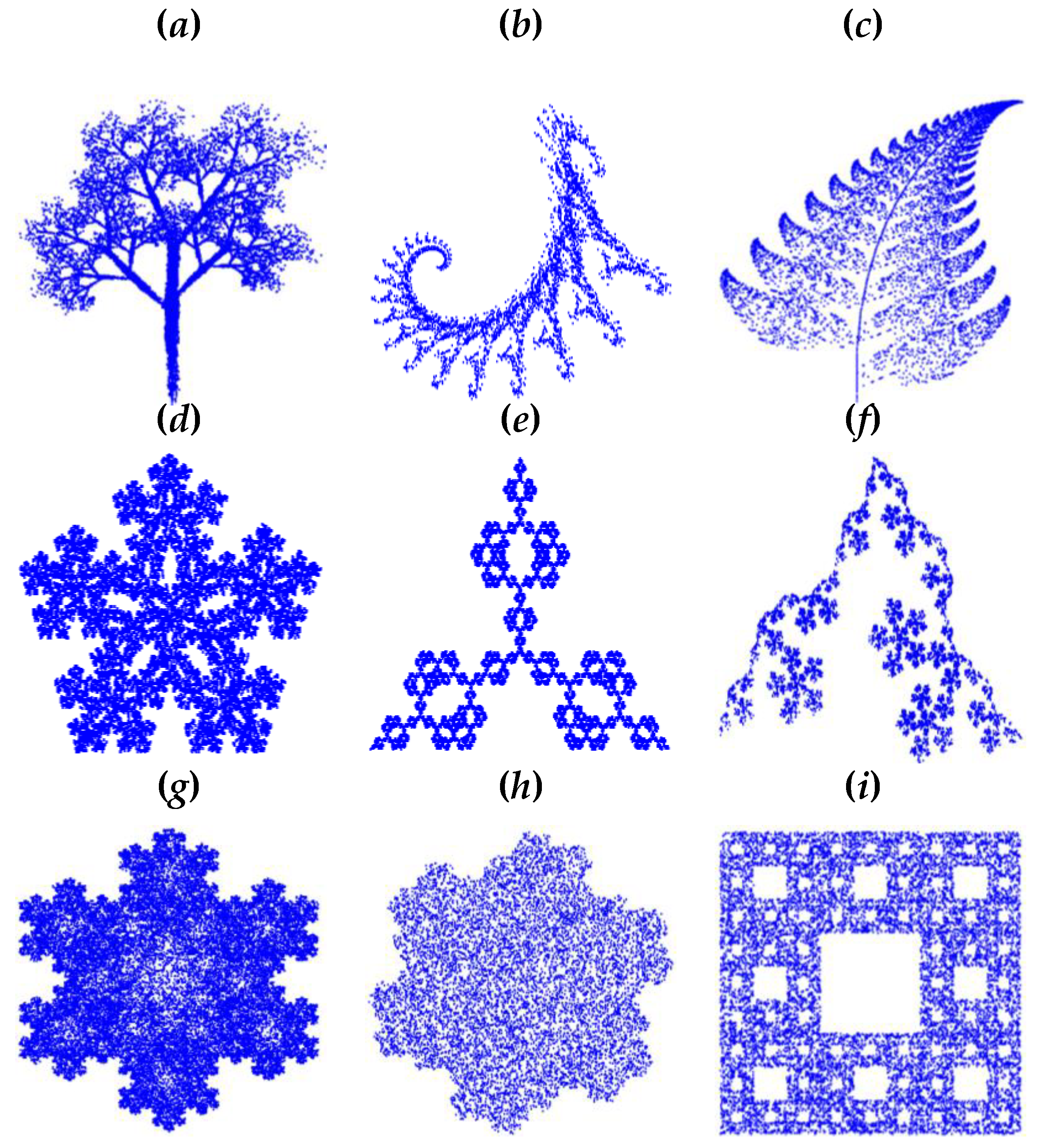
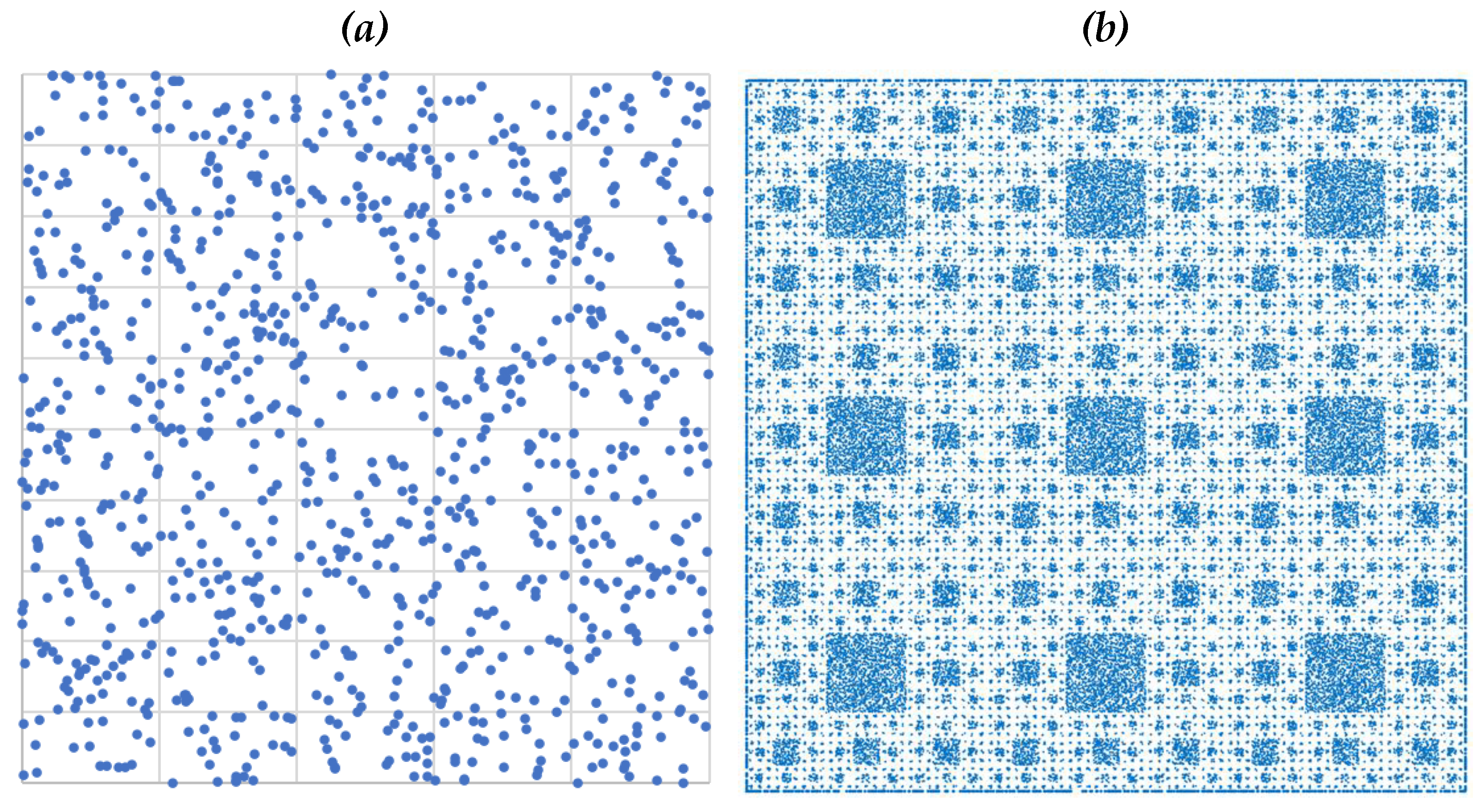
2. Settings of IFS-Based Fractals

This section presents the mathematical settings to generate IFS-based fractals.
IFS-based fractals are created by some strictly contracting affine maps, as described in [71,72,73,74]. Predefined probabilities control the frequency of participation of each map. To be more specific, we consider the following mathematical settings.
Let {(xi, yi) | i = 1, …, N} be the set of the recursively created point clouds where the initial point is (x0, y0) = (0, 0). The relationship between two consecutive points (xi−1, yi−1) and (xi, yi), i = 1, …, N, is as follows:
x i = a j x i 1 + b j y i 1 + e j , y i = c j x i 1 + d j y i 1 + f j ,   j { 1 , , M }
The vector of parameters (aj, bj, cj, dj, ej, fj) defines the j-th map. The values of the elements of this vector must be set in a way so that they collectively ensure a strictly contracting map as described in [71,72,73,74]. In the mapping processes, multiple maps can be used. Let M be the number of maps to be used. While mapping (xi−1, yi−1) into (xi, yi), a map out of M maps can be selected randomly. The (random) selection process must be controlled. As such, probabilities pj ∈ [0, 1], ∀j ∈ {1, …, M} are assigned to the maps so that p1 + … + pM = 1. Thus, after performing the mapping process N times, the frequency of the j-th map participating in the mapping process must be about pj × N. To achieve this, first, the cumulative probability of each map, denoted as cpj, is calculated as follows:
c p j = p 1 + + p j
The two consecutive cumulative probabilities produce an interval. This interval, in turn, determines the weight (wj) of the respective map. For the first and last maps, the weights are w1 = [0, cp1) and wM = [cpM−1, cpM], respectively. For others, the weights are wj = [cpj−1, cpj), ∀j∈{2, …, M − 1}. This means that the weights are mutually exclusive intervals that partition the interval [0, 1] so that {wj | j = 1, …, M} = [0, 1] and wjwj + 1 = Ø, ∀j∈{1, …, M − 1}. Thus, the following relationship holds:
w j = { [ 0 , c p 1 ) ,   j = 1 [ c p M 1 , c p M = 1 ] ,   j = M   [ c p j 1 , c p j )   o t h e r w i s e
If a random number denoted as ri ∀ [0, 1] (i = 1, 2, …) belongs to wj, the corresponding map participates in the mapping process, others not. This ensures the relative frequencies of the respective maps according to pj provided that the number of iterations N is relatively large.
Based on the above consideration, the IFS-based point cloud creation process follows an algorithmic approach. This approach can be defined by an algorithm denoted as the IFS Algorithm. The main processes of the IFS Algorithm are presented in Algorithm 1.
Algorithm 1 The main processes of the IFS
Fractalfract 05 00040 i001
The point cloud denoted as PC produced by the IFS Algorithm is the stochastic point cloud representing the given fractal shape. For example, Figure 4 shows nine point-clouds representing nine different fractal shapes (tree, seahorse, fern leaf, snowflakes, and the Sierpinski Carpet). The settings of the affine maps {(aj, bj, cj, dj, ej, fj, pj) | j = 1, …, M} can be found in [71,72,73,74]. The Sierpinski Carpet (Figure 4i) is considered in this study to model a porous structure. As far as manufacturing is concerned, the IFS Algorithm generated point cloud must undergo some transformation, controlling the self-similarity levels. For example, consider the case in Figure 5. Figure 5a shows a point cloud of fern leaf (same as Figure 4c). Figure 5b shows the same shape; this time, the self-similarity is controlled up to level three. The self-similarity level controlling mechanism employs a set of one-to-one maps. Sometimes, selected affine maps out of M maps can be omitted for the sake of controlling the level of self-similarity. See [72,73] for the details. It is worth mentioning that self-similar structures created by tree-like fractals have been used to reinforce a 3D printed structure [75,76]. In this case, solid models, not the point cloud, of the self-similar segments are used, which is not the focus in this study. However, the manufacturability of these self-similar segments limits the level up to which the self-similar tentacles can be fabricated with required accuracy [72,73,77].

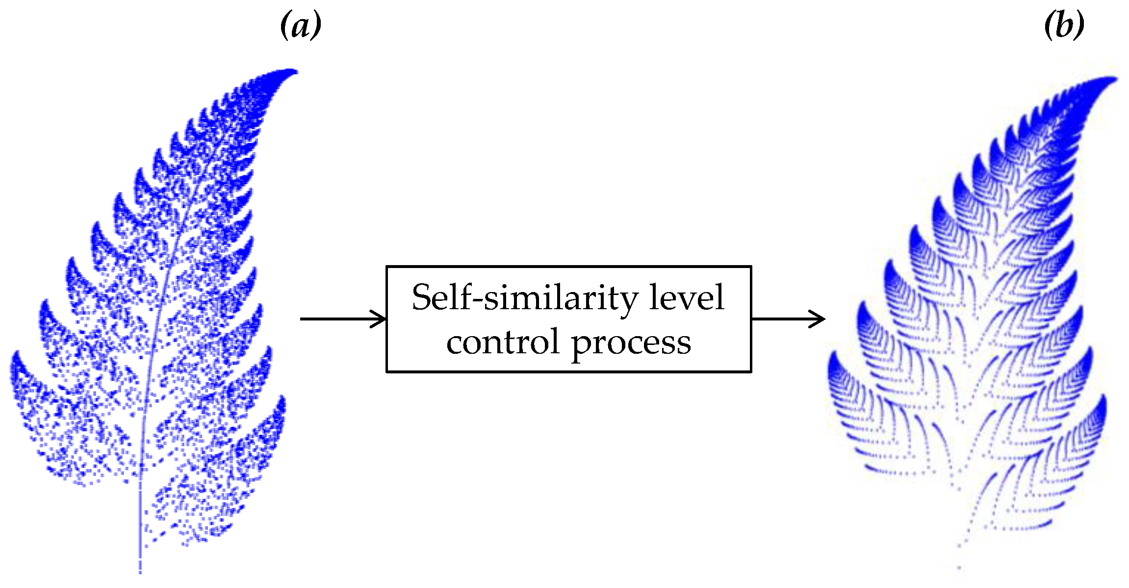
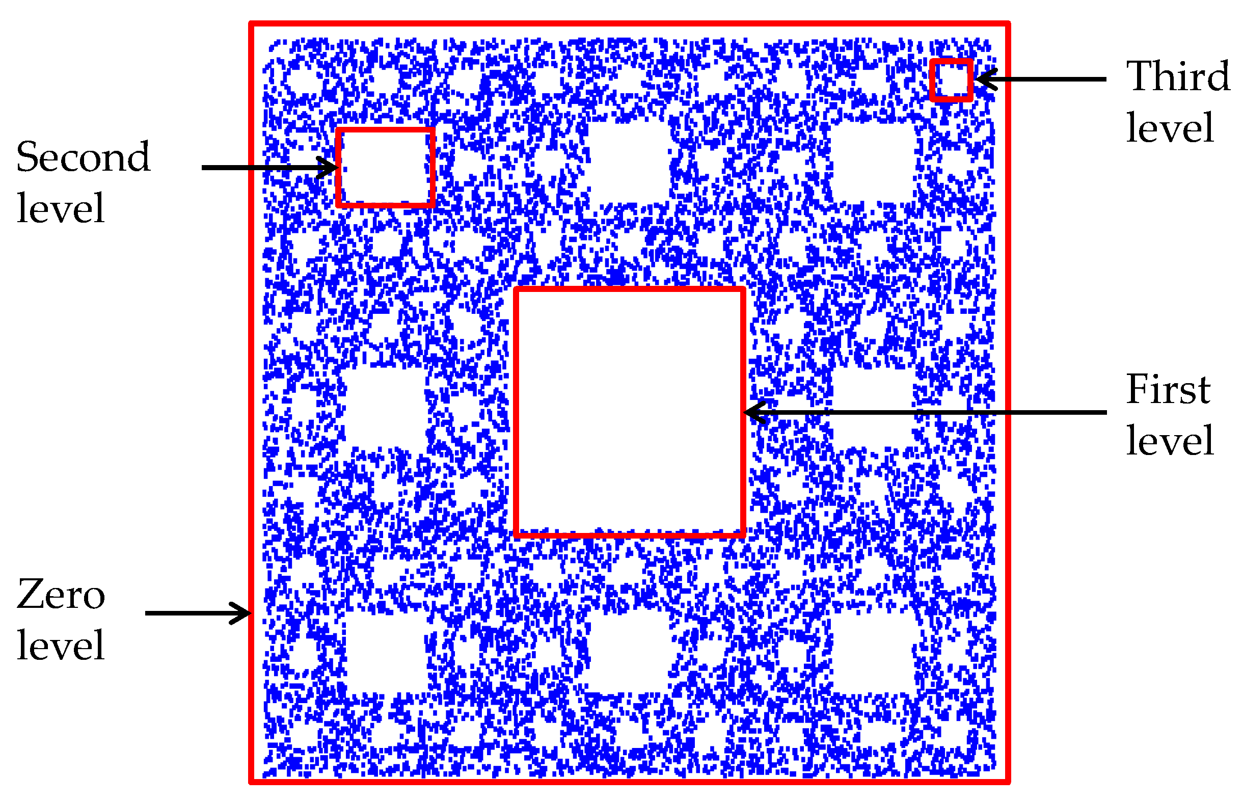
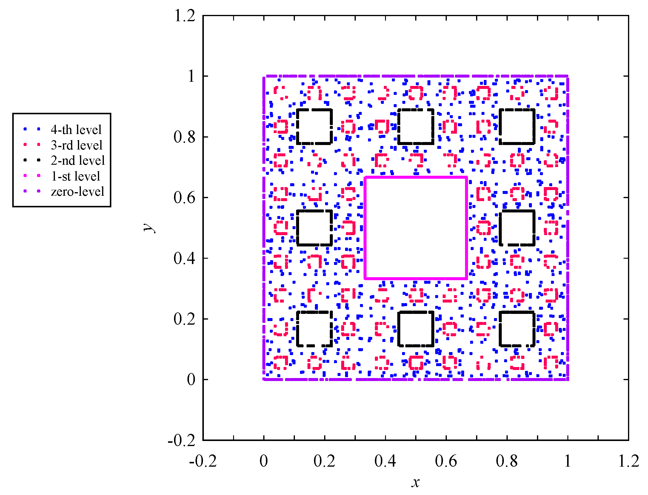
3. Controlling Self-Similarity Levels

This section presents how to control self-similarity levels of IFS fractal-driven point clouds to create models of porous structures.
A process consisting of five steps is proposed to control the self-similarity levels of IFS fractal-driven point clouds. The description of these steps is as follows.
Step 1: This step generates a seed point cloud denoted as PCS = {(xsi, ysi)|i = 0, 1, …, N} by an IFS-based fractal or by any other means. The number of points PCS must be chosen carefully so that the desired pore size can be achieved after performing the modifications described in Steps 2, …, 5.
Step 2: This step generates the first generation modified point cloud representing the first level of the underlying self-similar fractal or porous structure denoted as PCG−1 = {(xG−1,i, yG−1,i) | i = 0, 1, …, N}. The following one-to-one map is applied to each point in PCS to get its counterpart in PCG−1. Thus, the following relationship holds:
x G 1 , i = a c x s i + b c y s i + e c ,   y G 1 , i = c c x s i + d c y s i + f c ,   i { 0 , , N }
The mapping parameters (ac, bc, cc, dc, ec, fc) are denoted as critical parameters. The goal here is to bring the PCS to a region resulting in the first level self-similar shape of the underlying fractal or porous structure.
Step 3: This step generates the second generation modified point cloud denoted as PCG−2 = {(xG−2,i, yG−2,i) | i = 0, 1, …, N} representing the second level of the underlying self-similar fractal or porous structure. The following one-to-one map is applied to each point in PCG−1 to get its counterpart in PCG−2. As defined in (4), one of the affine maps of the underlying IFS fractal out of M maps are randomly selected to map a point (xG−1,i, yG−1,i) to (xG−2,i, yG−2,i). Thus, the random selection process is defined in Algorithm 2, which is like “Map” segment of IFS Algorithm 1:
Algorithm 2 IFS-inspired mapping
Fractalfract 05 00040 i002
Step 4: This step generates the third, fourth, …, generations of modified point clouds, denoted as PCG−3, PCG−4, …, respectively, repeating the mapping process defined in Step 3. The repetition process can be terminated based on the preference of the modeler. For example, if the modeler wants the third level self-similar shapes, Step 4 will be repeated one time only. Similarly, if the modeler wants the fourth level self-similar shapes, Step 4 will be repeated twice.
Step 5: This step first generates a filler point could denoted as PCF = {(xF,k, yF,k) | k = 0, …, L} and fills the empty regions PCG−1, PCG−2, PCG−3, …, following the mapping processes defined in Step 2,3, …, respectively. Let PCF′ be the point clouds generated in this step.
A point cloud consisting of PCG−1, PCG−2, …, and PCF′ can be used to model a porous structure. Nevertheless, the above steps are the general procedure for creating a model of a porous structure. The sequences of the steps can be designed based on the need of the modeler. For example, a modeler can apply Step 1, Step 2, Step 5, Step 3, Step 4, Step 4, and Step 4 successively. Another modeler can apply Step 1, Step 2, Step 3, Step 4, Step 5, successively. This means that depending on the need or preferences of a model, the steps and their sequence can be determined. There is no restriction as such.

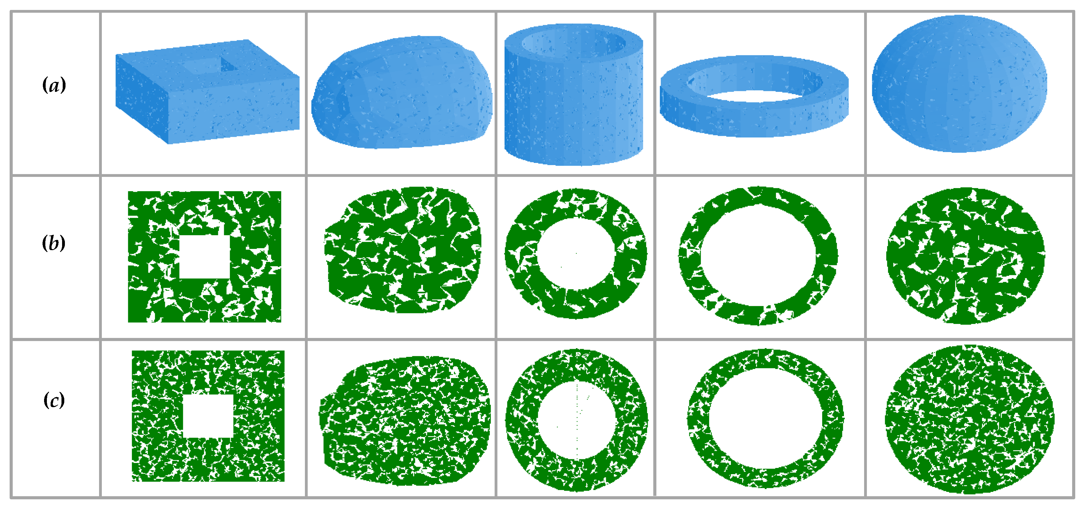
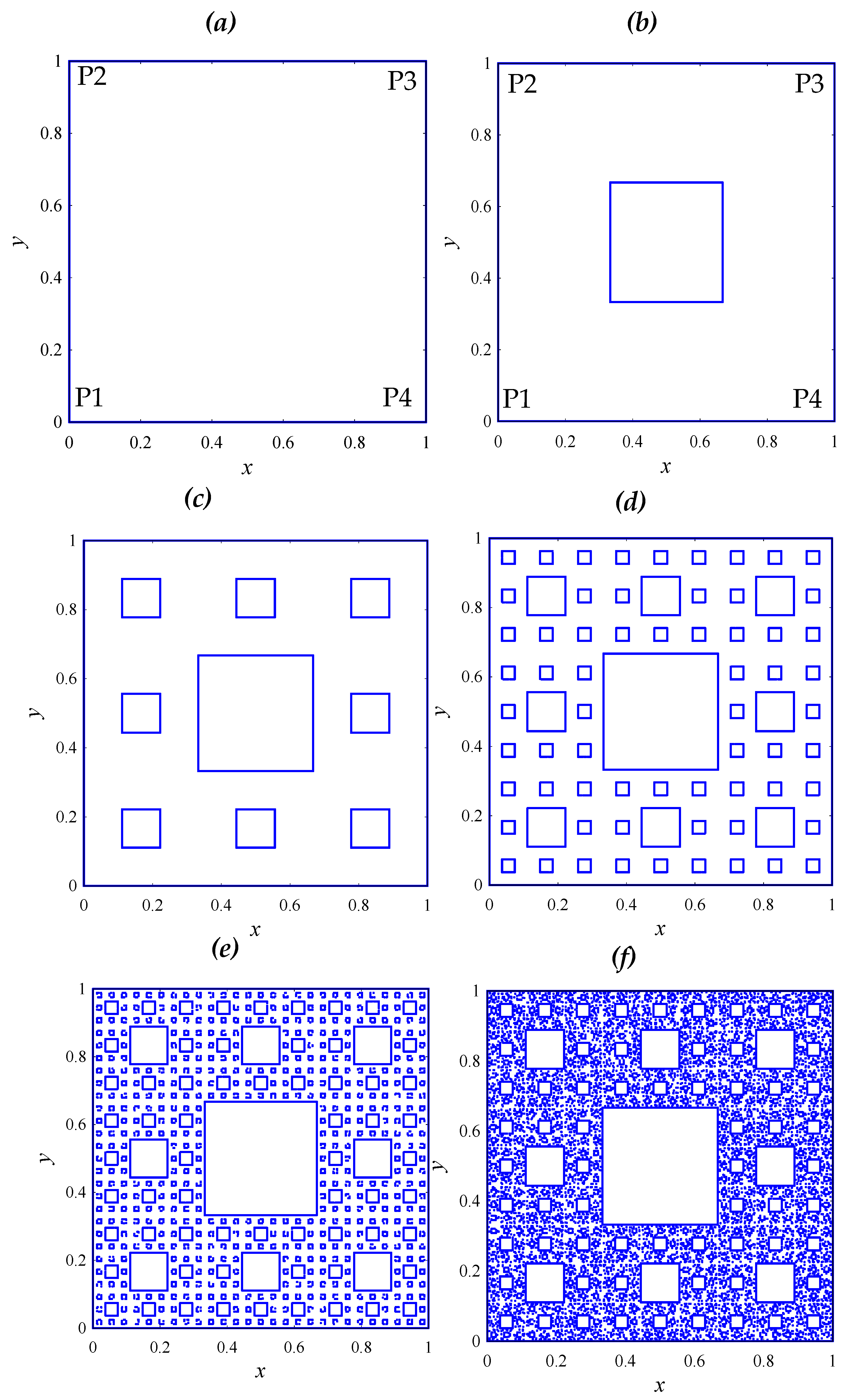
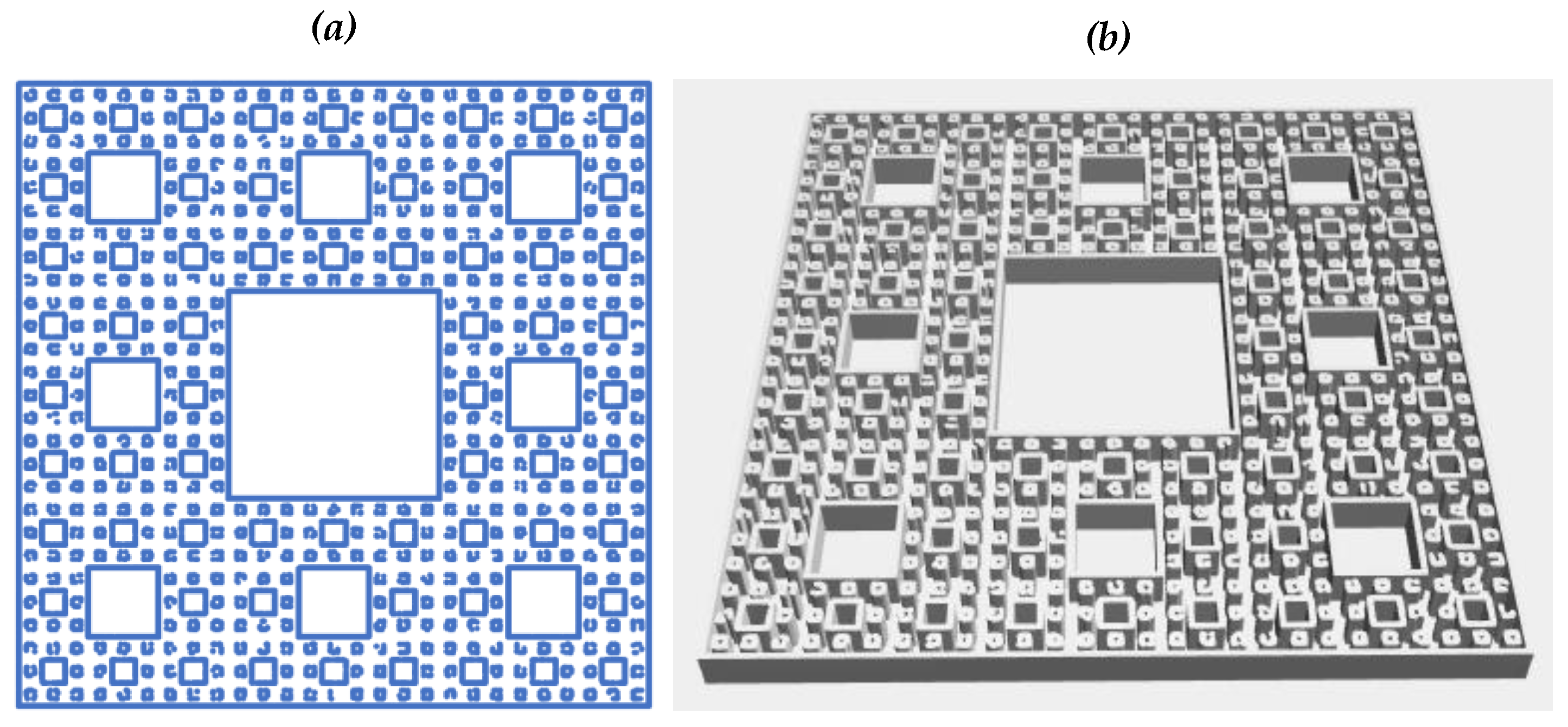
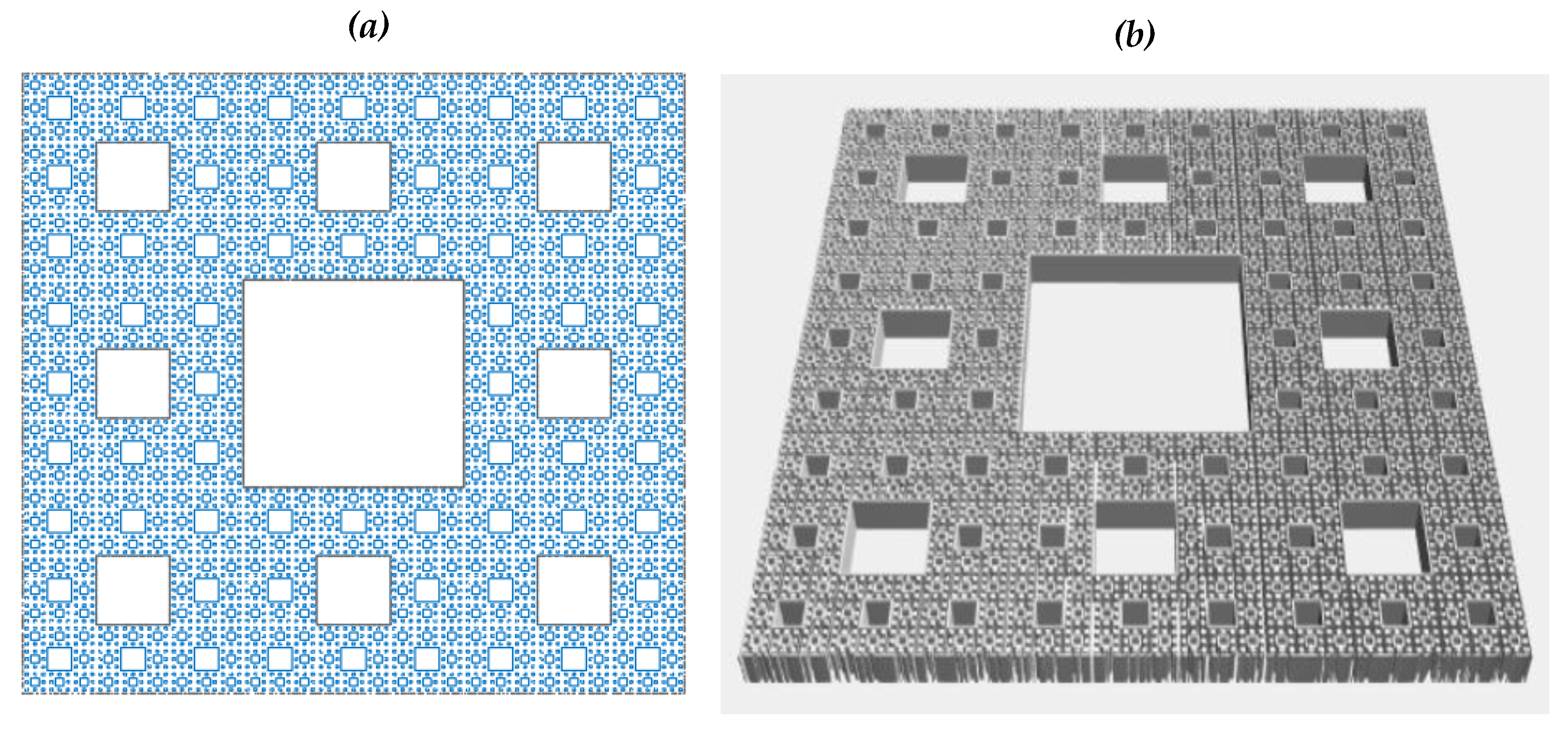
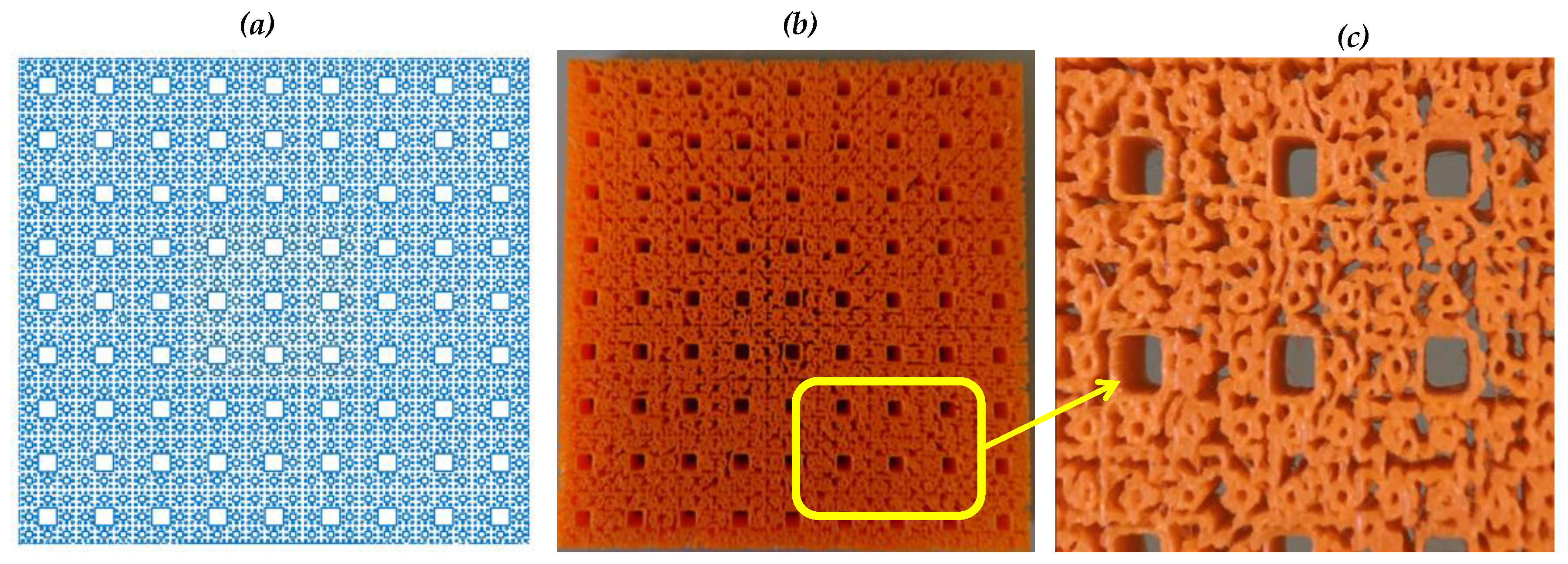
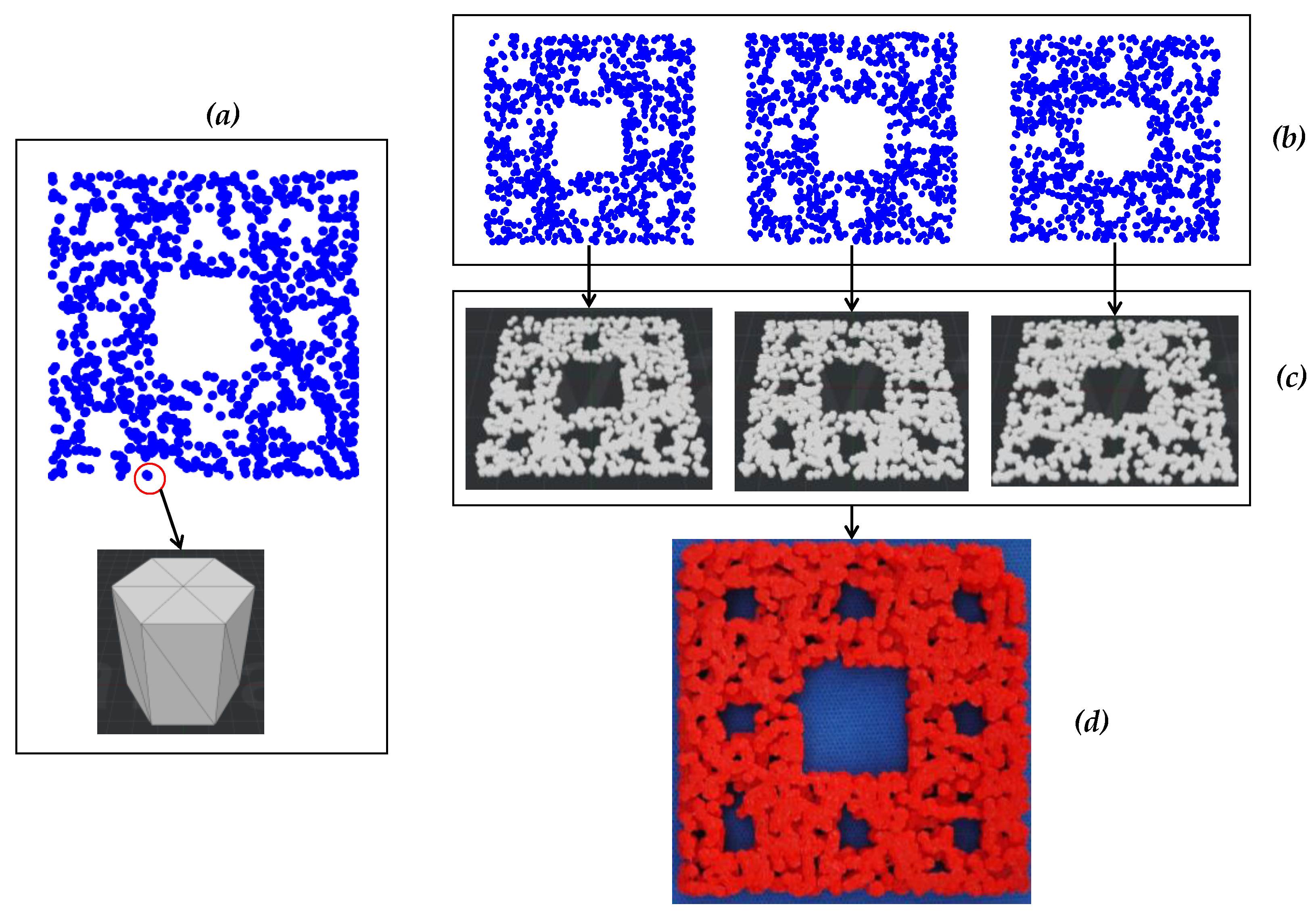
4. Modeling Porous Structures Using Sierpinski Carpet

This section shows how to modify the Sierpinski Carpet-driven point cloud (an IFS fractal, shown in Figure 4i) so that it becomes a porous structure model. The steps presented in the previous section will be used to achieve this goal.
First, consider the settings of the IFS fractal called the Sierpinski Carpet. The settings of the Sierpinski Carpet [74] are listed in Table 1. As listed in Table 1, the Sierpinski Carpet needs eight affine maps with equal weights (probability) of 1/8. The maps create a point cloud that resides in a square-shaped boundary given by vertices (0, 0) (1, 0), (1, 1), and (0, 1). The distribution of points creates self-similar squares, as shown in Figure 6. As seen in Figure 6, the self-similarity is scaled by 1/3. The maps symmetrically distribute the points around the scaled squares. As seen in Figure 6, the self-similar levels above the third level are not visible. If more points are injected (i.e., N is increased), the higher levels might be visible. This issue is, however, beyond the scope of this study.
Let us apply Steps 1, …,5 and modify the point cloud in Figure 6.
Step 1 is applied as follows: the seed point cloud (PCS) is created using the zero-level shape (Figure 6). The zero-level shape consists of lines P1P2, P2P3, P3P4, and P4P1, where P1 = (0, 0), P2 = (1, 0), P3 = (1, 1), and P4 = (0, 1), as shown in Figure 7a. As such, PCS = {(xsi, ysi)|i = 0, 1, …, N} consists of the points on the lines P1P2, P2P3, P3P4, and P4P1.
Step 2 is applied as follows: the first-level self-similar shape is created by scaling the points of PCS by a factor of 1/3, resulting in PCG−1 = {(xG−1,i, yG−1,i) | i = 0, 1, …, N}. For this, the following formulation is used:
x G 1 , i = 1 3 x s i + 1 3 ,   y G 1 , i = 1 3 y s i + 1 3 ,   i { 0 ,   ,   N }
As such, the values of the critical parameters are ac = 1/3, bc = 0, cc = 0, dc = 1/3, ec = 1/3, and fc = 1/3. The point clouds PCS and PCG−1 are shown in Figure 7b.
Step 3 is applied as follows. The affine maps shown in Table 1 are used to create the second-generation modified point cloud PCG−2 from PCG−1, as defined in Algorithm 2. The point clouds PCS, PCG−1, and PCG−2 are shown in Figure 7c.
Step 4 is applied as follows. This time, it is applied thrice. The first execution of Step 4 on the point cloud PCG−2 results in the third level self-similar squares given by the point cloud PCG−3. The point clouds PCS, PCG−1, PCG−2, and PCG−3 are shown in Figure 7d. The second execution of Step 4 on the point cloud PCG−3 results in the fourth level self-similar squares given by the point cloud PCG−4. The point clouds PCS, PCG−1, PCG−2, PCG−3, and PCG−4 are shown in Figure 7e. The third execution of Step 4 on the point cloud PCG−4 results in the fifth level self-similar squares given by the point cloud PCG−5. The point clouds PCS, PCG−1, PCG−2, PCG−3, PCG−3, PCG−4, and PCG−5 are shown in Figure 7f. Note that starting from the fourth level, the self-similar squares are not clearly manifested. This is because of the shortage of points in the seed, i.e., the PCS. For example, Figure 8 shows a case of the point clouds up to the fourth level. This time, a smaller number of points in the seed point cloud is used compared to the case shown in Figure 7. As seen in Figure 8, starting from the third level, the self-similar squares were not clearly manifested. Whether or not this is desirable from the context of porous structuring needs further investigation. This issue is kept out of the scope of this study, however.
Step 5 is applied as follows. Recall that Step 5 is an additional step, which can be applied before or after Steps 3 and 4. The goal is to fill the voids in certain regions of a given level of self-similarity. In this case, a filler point cloud PCF = {(xF,k, yF,k) | k = 0, 1, …, L} is a random point cloud in the interval of [0, 1]. Thus, xF,k ∈ [0, 1] and yF,k ∈ [0, 1], ∀k ∈ {0, …, L}. One of the examples of PCF is shown in Figure 9a. This point cloud is mapped using the procedure underlying Steps 2–4, where the affine maps of the Sierpinski Carpet are used. The resulting point cloud (PCF′) is shown in Figure 9b. As seen in Figure 9b, this time, the level-controlled pores are filled by points. Therefore, this point cloud (PCF’) can be added to the level-controlled point cloud if the pores are not desired.

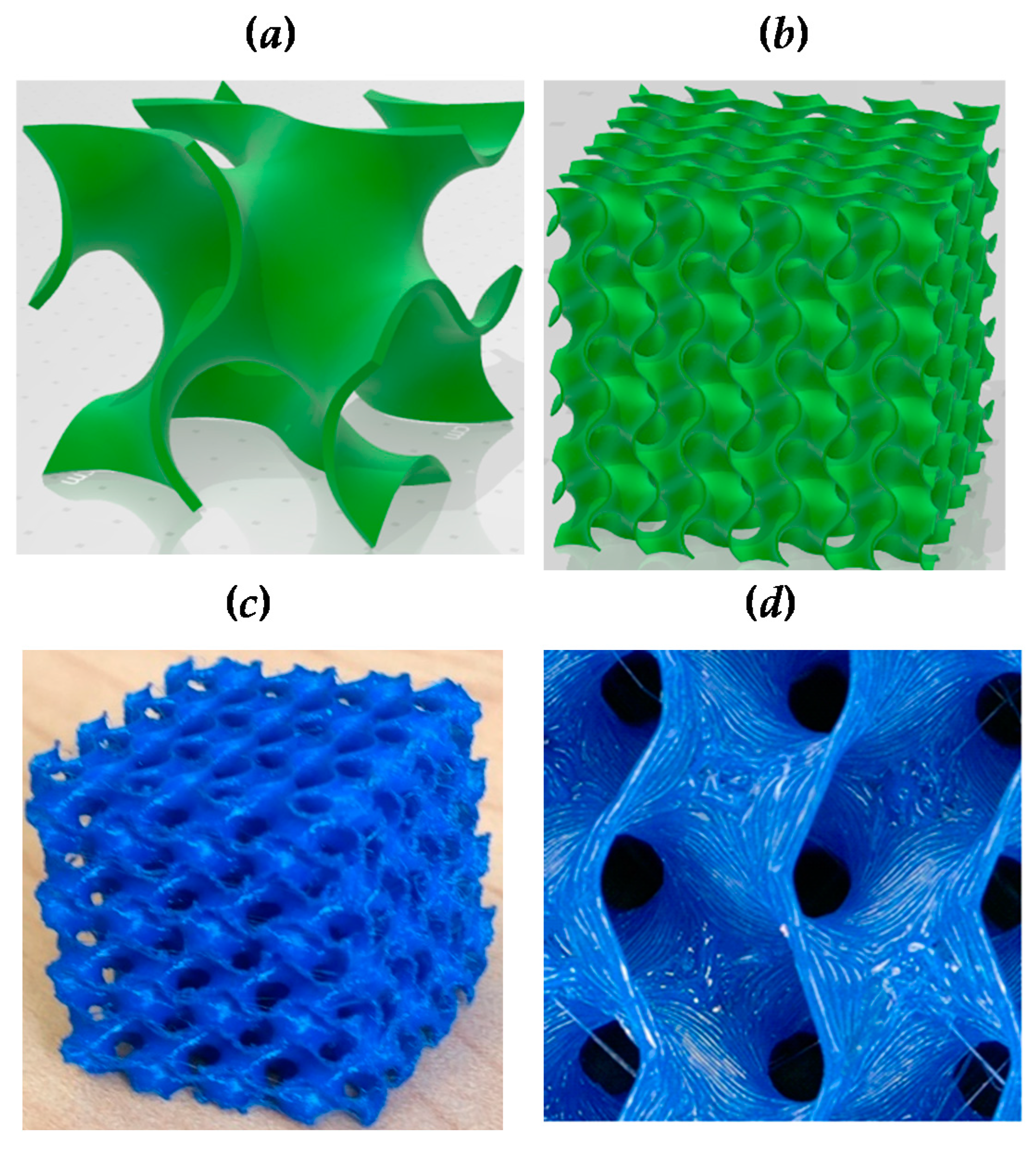
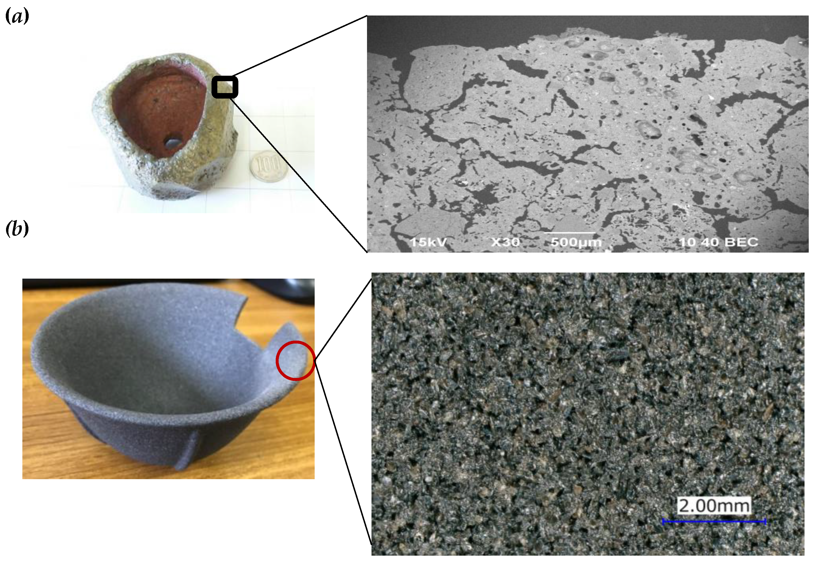
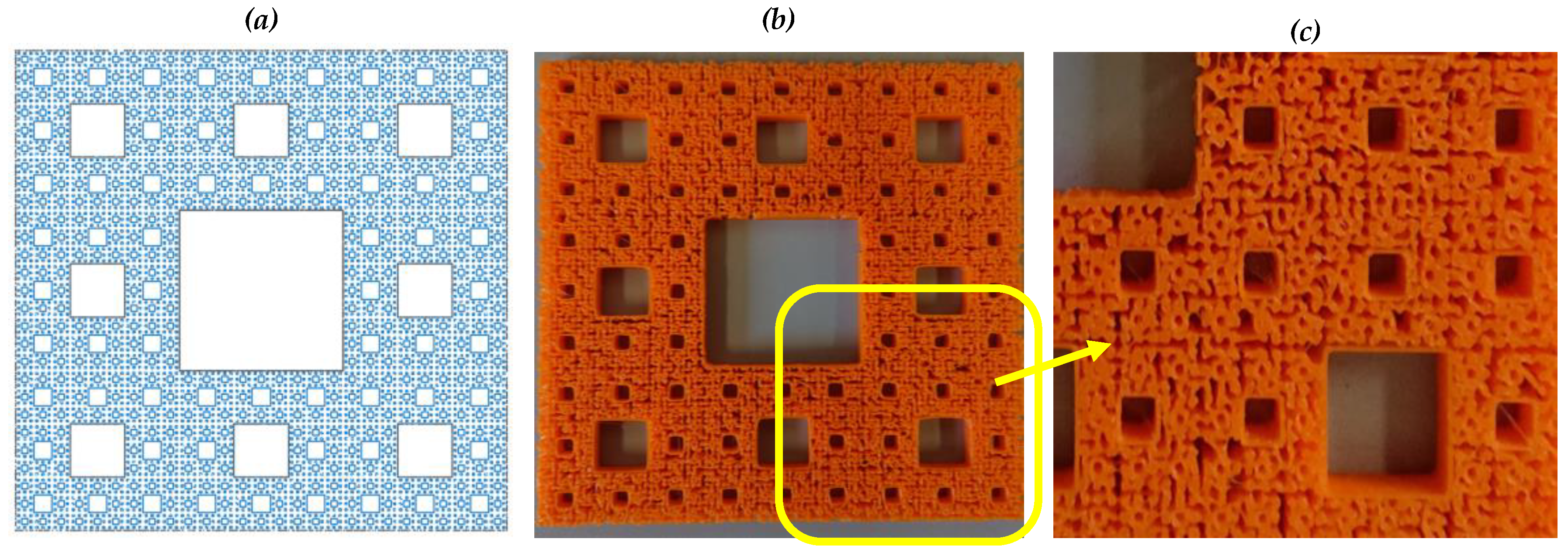
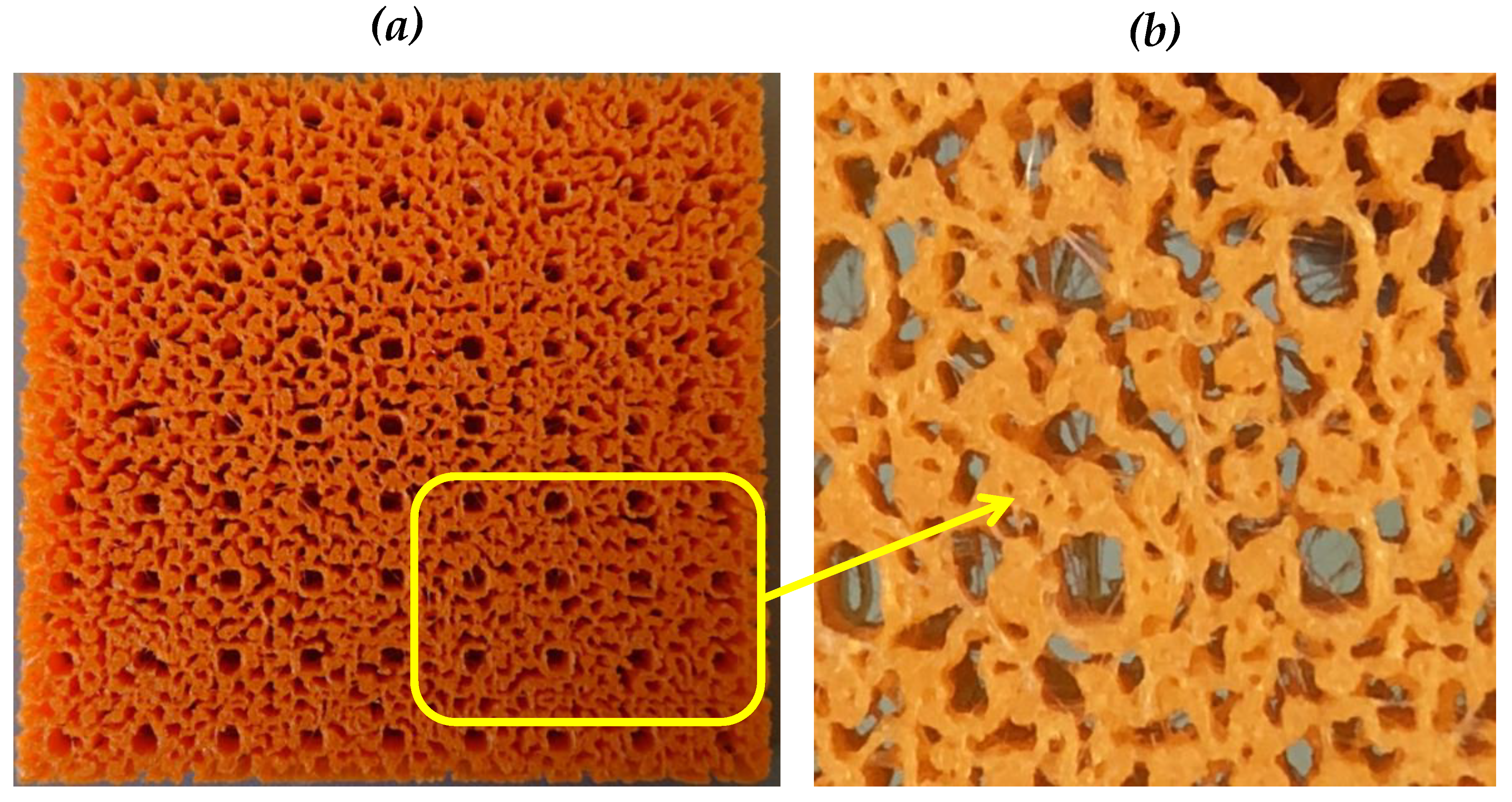
5. Solid Modeling and 3D Printing

This section shows some solid models of porous structures, as well as the 3D printed structures.
Figure 10 shows the point clouds controlled up to the fourth level and its solid model. The point clouds used in this case are shown in Figure 10a. The solid CAD model, shown in Figure 10b, is created using commercially available software that can convert a raster graphics entity into a vector graphics entity using voxel-based geometric modeling. Figure 11 shows another similar case. This time, the point clouds, shown in Figure 11a, controlled up to the fifth level is considered. The corresponding solid CAD model is shown in Figure 11b. This way, a user can apply the procedure described in Section 3 and Section 4 to digitize a porous structure model given the level-controlled point clouds of the IFS fractal.
To obtain more insights into the fabrication of porous structures, a commercially available 3D printer is used. Several 3D-printed structures have been produced. Three of the results are shown in this section. Figure 12 shows the point clouds controlled up to level five, the corresponding 3D-printed structure, and a magnified view of the structure. As seen in Figure 12, the porous structure exhibits a complex network among the pores in the structure. This is partly because of the limitation of the solid CAD model and partly because of the limitation of the 3D printer.
Figure 13 shows the point clouds controlled up to level five, the corresponding 3D-printed structure, and a magnified view of the structure. This time, the filling operation was carried out, as descried in the previous section. Thus, in the point clouds (Figure 13a), the first and second level self-similar square regions are not filled with points. The corresponding porous structure (Figure 13b,c) exhibits a complex network among pores. As seen in Figure 13, the porous structure exhibits a complex network among the pores in the structure. Like the previous case, this is partly because of the limitation of the solid CAD model and partly because of the limitation of the 3D printer.
What if the structure is scaled down while printing it? When the structure is produced by reducing the scale, the pore network becomes more complex. As a result, randomness in the pore sizes increases. This is because of the limitation of the 3D printer. For example, consider the case shown in Figure 14. The point clouds shown in Figure 13 are used to print the structure shown in Figure 14. The structure is scaled down by half during the printing, resulting in a more complex network among the pores than that of Figure 13.
In addition to using a voxel-based solid modeling of porous structure from level-controlled point clouds of IFS fractals, other solid modeling approaches can be used. In this respect, one of the obvious modeling approaches is to model each point of the point clouds by using special polyhedrons (e.g., prismoid). For example, consider the case shown in Figure 15. In this case, the modeling concept is to model each point of an IFS-generated point cloud (in this case, a point cloud representing Sierpinski Carpet created by the IFS Algorithm defined in Algorithm 1) by a hexagonal cylinder (see Figure 15a). This way, multiple point clouds can be created and solid modeled. The point clouds look alike but are not the same due to the stochasticity involved in point cloud creation process (see IFS Algorithm 1). In Figure 15b, three point clouds are shown to be modeled by the proposed concept. The solid models of these point clouds are shown in Figure 15c. Finally, these solid models can be combined to print a porous structure. One printed porous structure is shown in Figure 15d.
In synopsis, IFS-generated stochastic point clouds provide a flexible means to model porous structures, and thereby, to fabricate them using 3D printing or additive manufacturing.

6. Concluding Remarks

There are many application areas where porous structures with randomly sized and distributed pores are required, e.g., biomedical applications (producing implants), materials science (developing cermet-based materials with desired properties), engineering applications (objects having controlled mass and energy transfer properties), and smart agriculture (devices for soilless cultivation). In most cases, a scaffold-based method is used to design porous structures. This approach fails to produce randomly sized and distributed pores. Thus, more effective porous structure design methods are required. In this respect, methods capable of filling the spaces offered by a stochastic point cloud are quite effective. IFS-based fractals manifest stochastic point clouds. Thus, these point clouds are candidates for porous structure design. This possibility is explored in this study, and some promising results are obtained.
A mathematical procedure is developed to create stochastic point clouds using the affine maps of a predefined IFS-based fractal. In addition, a method is developed to modify a given IFS fractal-generated point cloud. The modification process controls the self-similarity levels of the fractal and ultimately results in a model of porous structure exhibiting randomly sized and distributed pores. The model can be transformed into a 3D CAD model using voxel-based modeling or other means for digitization and 3D printing.
The efficacy of the proposed method is demonstrated by transforming the Sierpinski Carpet (an IFS-based fractal) into 3D printed porous structures. The condition of achieving fractal geometry-created porous structure must follow a definite sequence of mapping combining some predefined one-to-one and affine mappings. The sequence of mapping must control the self-similar structures as well as fill some preselected regions. The sequence of mapping for the Sierpinski Carpet-based porous structuring is elucidated. The proposed mathematical procedure is effective in this regard, as demonstrated in this study using the case of Sierpinski Carpet-generated point clouds. Other IFS-based fractals than the Sierpinski Carpet can be used to model and fabricate porous structures effectively. This issue remains open for further research.
The four different printed porous structures presented here demonstrate that the fractal-based porous structuring creates a complex network among randomly sized and distributed pores in the structure.
Fractal geometry is well known for modeling and quantifying complex shapes observed in the natural world, living organisms, and artificial objects (particularly in micro-nano scale). In this respect, the concepts of self-similarity and fractal dimensions are extensively used. On the other hand, fractal geometry’s ability to produce stochastic points has not yet been explored. As demonstrated in this study, IFS-based fractals are an effective means to produce a stochastic point cloud, which can model realistic porous structures. Thus, this study extends the scope of fractal geometry to a large extent.
Conducting experimental studies employing real porous structures (including cermet-based porous structures), is expensive and requires a long time. Before performing experimental studies employing real porous structures, preliminary experiments can be performed using 3D printed artificial porous structures. The results of preliminary experiments can be used to optimize the experimental studies employing real porous structures. Thus, the outcomes of this study can be used to reduce the expense and time of porous structure-related experimental studies. This issue is also open for further investigation.

Author Contributions

Conceptualization, A.S.U., D.M.D., Y.S., S.Y. and A.K.; methodology, A.S.U., D.M.D. and Y.S.; mathematical formulation, A.S.U.; modeling A.S.U., Y.S. and S.Y.; resources, A.S.U. and A.K.; 3D printing and data curation, A.S.U., Y.S., S.Y. and A.K.; writing—original draft preparation, A.S.U. and D.M.D.; writing—review and editing, A.S.U., D.M.D., Y.S. and S.Y.; supervision, A.S.U. and D.M.D. All authors have read and agreed to the published version of the manuscript.

Funding

This research received no external funding.

Data Availability Statement

The data are available from the corresponding author upon request.

Acknowledgments

Authors gratefully acknowledge Shota Yamamoto and Ryo Yamauchi for their assistances in modeling building and 3D printing activities.

Conflicts of Interest

The authors declare no conflict of interest.

References

  1. Mandelbrot, B.B. The Fractal Geometry of Nature; W.H. Freeman: New York, NY, USA, 1983. [Google Scholar]
  2. Frame, M.; Urry, A. Fractal Worlds: Grown, Built, and Imagined; Yale University Press: New Haven, CT, USA, 2016. [Google Scholar]
  3. Alan, F. Applications of fractal geometry to biology. Bioinformatics 1992, 8, 359–366. [Google Scholar]
  4. Otaki, J.M. The Fractal Geometry of the Nymphalid Groundplan: Self-Similar Configuration of Color Pattern Symmetry Systems in Butterfly Wings. Insects 2021, 12, 39. [Google Scholar] [CrossRef] [PubMed]
  5. Werner, D.H.; Haupt, R.L.; Werner, P.L. Fractal antenna engineering: The theory and design of fractal antenna arrays. IEEE Antennas Propag. Mag. 1999, 41, 37–58. [Google Scholar] [CrossRef] [Green Version]
  6. Mohanty, A.; Behera, B.R. Insights on radiation modes and pattern diversity of two element UWB fractal MIMO antenna using theory of characteristics modes analysis. AEU Int. J. Electron. Commun. 2021, 135, 153726. [Google Scholar] [CrossRef]
  7. Rmili, H.; Oueslati, D.; Ladhar, L.; Sheikh, M. Design of a chipless RFID tags based on natural fractal geometries for security applications. Microw. Opt. Technol. Lett. 2016, 58, 75–82. [Google Scholar] [CrossRef]
  8. Çalışkan, A.; Çevik, U. Three-dimensional modeling in medical image processing by using fractal geometry. J. Comput. 2017, 12, 479–485. [Google Scholar] [CrossRef]
  9. Goel, B.D.; Kwatra, S.C. A Data Compression Algorithm for Color Images Based on Run-Length Coding and Fractal Geometry. In Proceedings of the IEEE International Conference on Communications, Spanning the Universe, Philadelphia, PA, USA, 12–15 June 1988; Volume 3, pp. 1253–1256. [Google Scholar]
  10. Ludlow, D.K. Fractal Geometry Applications. In Particle Technology and Applications, 1st ed.; Lee, S., Henthorn, K.H., Eds.; CRC Press: Boca Raton, FL, USA, 2012. [Google Scholar]
  11. Zhou, Z.; Su, Y.; Wang, W.; Yan, Y. Application of the fractal geometry theory on fracture network simulation. J. Petrol. Explor. Prod. Technol. 2017, 7, 487–496. [Google Scholar] [CrossRef] [Green Version]
  12. Katona, V. Relief Method: The Analysis of Architectonic Façades by Fractal Geometry. Buildings 2021, 11, 16. [Google Scholar] [CrossRef]
  13. Lee, M.S. Application of Fractal Geometry to Architectural Design. Archit. Res. 2014, 16, 175–183. [Google Scholar] [CrossRef] [Green Version]
  14. Mandelbrot, B.B. How long is the coast of Britain? Statistical self-similarity and fractional dimension. Science 1967, 156, 636–638. [Google Scholar] [CrossRef] [PubMed] [Green Version]
  15. Avnir, D.; Farin, D.; Pfeifer, P. Molecular fractal surfaces. Nature 1984, 308, 261–263. [Google Scholar] [CrossRef]
  16. Pfeifer, P.; Avnir, D. Chemistry in noninteger dimensions between two and three: I. Fractal theory of heterogeneous surface. J. Chem. Phys. 1983, 79, 3558–3565. [Google Scholar] [CrossRef]
  17. Stewart, E. Towards numerically estimating Hausdorff dimensions. ANZIAM J. 2001, 42, 451–461. [Google Scholar] [CrossRef] [Green Version]
  18. Yong, H.; Changsong, S.; Xin, Y. Fractal signal processing method of acoustic emission monitoring for seismic damage of concrete columns. Int. J. Lifecycle Perform. Eng. 2019, 3, 59–76. [Google Scholar]
  19. Teti, R.; Segreto, T.; Caggiano, A.; Nele, L. Smart Multi-Sensor Monitoring in Drilling of CFRP/CFRP Composite Material Stacks for Aerospace Assembly Applications. Appl. Sci. 2020, 10, 758. [Google Scholar] [CrossRef] [Green Version]
  20. Namazi, H.; Qadri, M.O. Fractal-based analysis of the relation between tool wear and machine vibration in milling operations. Fractals 2020, 28, 2050101. [Google Scholar]
  21. Jiří, M.; Vladimír, B. Surface Roughness and Fractal Dimension. J. Text. Inst. 2001, 92, 91–113. [Google Scholar]
  22. Adcock, J.L.; Fulvio, P.F.; Dai, S. Towards the selective modification of soft-templated mesoporous carbon materials by elemental fluorine for energy storage devices. J. Mater. Chem. A 2013, 1, 9327–9331. [Google Scholar] [CrossRef]
  23. Xia, Y.; Yanga, Z.; Zhua, Y. Porous carbon-based materials for hydrogen storage: Advancement and challenges. J. Mater. Chem. A 2013, 1, 9365–9381. [Google Scholar] [CrossRef]
  24. Kalimuldina, G.; Nurpeissova, A.; Adylkhanova, A.; Issatayev, N.; Adair, D.; Bakenov, Z. 3D Hierarchical Nanocrystalline CuS Cathode for Lithium Batteries. Materials 2021, 14, 1615. [Google Scholar] [CrossRef] [PubMed]
  25. Pehlivan, E.; Džugan, J.; Fojt, J.; Sedláček, R.; Rzepa, S.; Daniel, M. Post-Processing Treatment Impact on Mechanical Properties of SLM Deposited Ti-6Al-4 V Porous Structure for Biomedical Application. Materials 2020, 13, 5167. [Google Scholar] [CrossRef]
  26. Hong, J.-Y.; Ko, S.-Y.; Lee, W.; Chang, Y.-Y.; Kim, S.-H.; Yun, J.-H. Enhancement of Bone Ingrowth into a Porous Titanium Structure to Improve Osseointegration of Dental Implants: A Pilot Study in the Canine Model. Materials 2020, 13, 3061. [Google Scholar] [CrossRef]
  27. Song, K.; Wang, Z.; Lan, J.; Ma, S. Porous structure design and mechanical behavior analysis based on TPMS for customized root analogue implant. J. Mech. Behav. Biomed. Mater. 2021, 115. [Google Scholar] [CrossRef] [PubMed]
  28. Zhang, X.; Mao, J.; Zhou, Y.; Ji, F.; Chen, X. Mechanical properties and osteoblast proliferation of complex porous dental implants filled with magnesium alloy based on 3D printing. J. Biomater. Appli. Sept. 2020. [Google Scholar] [CrossRef]
  29. Marco, M.; Belda, R.; Miguélez, M.H.; Giner, E. Numerical analysis of mechanical behaviour of lattice and porous structures. Compos. Struct. 2021, 261, 113292. [Google Scholar] [CrossRef]
  30. Ishibashi, S.; Shimada, K.; Kanetaka, H.; Tsukuda, M.; Mizoi, T.; Chuzenji, M.; Kikuchi, S.; Mizutani, M.; Kuriyagawa, T. Porosity and Tensile Properties of Rhizoid Porous Structure Fabricated Using Selective Laser Melting. Int. J. Autom. Technol. 2020, 14, 582–591. [Google Scholar] [CrossRef]
  31. Seto, Y.; Ullah, A.S.; Kubo, A.K.; D’Addona, D.M.; Teti, R. On the Porous Structuring using Unit Cells. Procedia CIRP 99C 2021. in print. [Google Scholar] [CrossRef]
  32. Zeng, Q.; Luo, M.; Pang, X.; Li, L.; Li, K. Surface fractal dimension: An indicator to characterize the microstructure of cement-based porous materials. Appl. Surface Sci. 2013, 282, 302–307. [Google Scholar] [CrossRef]
  33. Kim, J.; Choi, S. A fractal-based approach for reconstructing pore structures of GGBFS-blended cement pastes. Constr. Build. Mater. 2020, 265, 120350. [Google Scholar] [CrossRef]
  34. Gao, Y.; Wu, K.; Yuan, Q. Limited fractal behavior in cement paste upon mercury intrusion porosimetry test: Analysis and models. Constr. Build. Mater. 2021, 276, 122231. [Google Scholar] [CrossRef]
  35. Yang, J.; Liao, X.; Wang, G.; Chen, J.; Song, P.; Tang, W.; Guo, F.; Liu, F.; Li, G. Heterogeneous silicon rubber composite foam with gradient porous structure for highly absorbed ultra-efficient electromagnetic interference shielding. Compos. Sci. Technol. 2021, 206, 108663. [Google Scholar] [CrossRef]
  36. Neimark, A. A new approach to the determination of the surface fractal dimension of porous solids. Physica A Stat. Mechan. Appl. 1992, 191, 258–262. [Google Scholar] [CrossRef]
  37. Friesen, W.I.; Mikula, R.J. Fractal dimensions of coal particles. J. Colloid Interface Sci. 1987, 120, 263–271. [Google Scholar] [CrossRef]
  38. Zhang, B.; Li, S. Determination of the surface fractal dimension for porous media by mercury porosimetry. Ind. Eng. Chem. Res. 1995, 34, 1383–1386. [Google Scholar] [CrossRef]
  39. Zeng, Q.; Li, K.; Fen-Chong, T.; Dangla, P. Surface fractal analysis of pore structure of high-volume fly-ash cement pastes. Appl. Surface Sci. 2010, 257, 762–768. [Google Scholar] [CrossRef]
  40. Tang, S.; Huang, J.; Duan, L.; Yu, P.; Chen, E. A review on fractal footprint of cement-based materials. Powder Technol. 2020, 370, 237–250. [Google Scholar] [CrossRef]
  41. Wang, L.; Jin, M.; Wu, Y.; Zhou, Y.; Tang, S. Hydration, shrinkage, pore structure and fractal dimension of silica fume modified low heat Portland cement-based materials. Constr. Build. Mater. 2021, 272, 121952. [Google Scholar] [CrossRef]
  42. Wang, L.; Guo, F.; Yang, H. Comparison of fly ash, PVA fiber, MgO and shrinkage-reducing admixture on the frost resistance of face slab concrete via pore structural and fractal analysis. Fractals 2021, 29, 2140002. [Google Scholar] [CrossRef]
  43. Wang, L.; Luo, R.; Zhang, W. Effects of fineness and content of phosphorus slag on cement hydration, permeability, pore structure and fractal dimension of concrete. Fractals 2021, 29, 2140004. [Google Scholar] [CrossRef]
  44. Wang, L.; Jin, W.; Guo, F. Pore structural and fractal analysis of the influence of fly ash and silica fume on the mechanical property and abrasion resistance of concrete. Fractals 2021, 29, 2140003. [Google Scholar] [CrossRef]
  45. Ullah, A.S.; Tashi; Kubo, A.; Harib, K.H. Tutorials for Integrating 3D Printing in Engineering Curricula. Educ. Sci. 2020, 10, 194. [Google Scholar] [CrossRef]
  46. Liu, L.; Yang, X.; Bhandari, B.; Meng, Y.; Prakash, S. Optimization of the Formulation and Properties of 3D-Printed Complex Egg White Protein Objects. Foods 2020, 9, 164. [Google Scholar] [CrossRef] [PubMed] [Green Version]
  47. Awad, A.; Yao, A.; Trenfield, S.J.; Goyanes, A.; Gaisford, S.; Basit, A.W. 3D Printed Tablets (Printlets) with Braille and Moon Patterns for Visually Impaired Patients. Pharmaceutics 2020, 12, 172. [Google Scholar] [CrossRef] [PubMed] [Green Version]
  48. Tao, Y.; Li, Z.; Li, P. A Design and Fabrication Method for Wood-Inspired Composites by Micro X-Ray Computed Tomography and 3D Printing. Appl. Sci. 2020, 10, 1400. [Google Scholar] [CrossRef] [Green Version]
  49. Tashi; Ullah, A.S. Symmetrical Patterns of Ainu Heritage and Their Virtual and Physical Prototyping. Symmetry 2019, 11, 985. [Google Scholar] [CrossRef] [Green Version]
  50. Takeuchi, Y. 3D Printable Hydroponics: A Digital Fabrication Pipeline for Soilless Plant Cultivation. IEEE Access 2019, 7, 35863–35873. [Google Scholar] [CrossRef]
  51. Saleh, M.S.; Li, J.; Park, J.; Panat, R. 3D printed hierarchically-porous microlattice electrode materials for exceptionally high specific capacity and areal capacity lithium ion batteries. Addit. Manuf. 2018, 23, 70–78. [Google Scholar] [CrossRef]
  52. Beecroft, M. 3D printing of weft knitted textile based structures by selective laser sintering of nylon powder. IOP Conf. Ser. Mater. Sci. Eng. 2016, 137, 012017. [Google Scholar] [CrossRef]
  53. Melnikova, R.; Ehrmann, A.; Finsterbusch, K. 3D printing of textile-based structures by Fused Deposition Modelling (FDM) with different polymer materials. IOP Conf. Ser. Mater. Sci. Eng. 2014, 62, 012018. [Google Scholar] [CrossRef] [Green Version]
  54. Skylar-Scott, M.A.; Gunasekaran, S.; Lewis, J.A. Laser-assisted direct ink writing of planar and 3D metal architectures. Proc. Natl. Acad. Sci. USA 2016, 113, 6137–6142. [Google Scholar] [CrossRef] [Green Version]
  55. Huber, T.; Clucas, D.; Vilmay, M.; Pupkes, B.; Stuart, J.; Dimartino, S.; Fee, C. 3D Printing Cellulose Hydrogels Using LASER Induced Thermal Gelation. J. Manuf. Mater. Process. 2018, 2, 42. [Google Scholar] [CrossRef] [Green Version]
  56. Elsayed, H.; Chmielarz, A.; Potoczek, M.; Fey, T.; Colombo, P. Direct ink writing of three dimensional Ti2AlC porous structures. Addit. Manuf. 2019, 28, 365–372. [Google Scholar]
  57. Barile, G.; Leoni, A.; Muttillo, M.; Paolucci, R.; Fazzini, G.; Pantoli, L. Fused-Deposition-Material 3D-Printing Procedure and Algorithm Avoiding Use of Any Supports. Sensors 2020, 20, 470. [Google Scholar] [CrossRef] [Green Version]
  58. Guo, Y.; Liu, K.; Yu, Z. Tetrahedron-Based Porous Scaffold Design for 3D Printing. Designs 2019, 3, 16. [Google Scholar] [CrossRef] [Green Version]
  59. Domínguez-Robles, J.; Mancinelli, C.; Mancuso, E.; García-Romero, I.; Gilmore, B.F.; Casettari, L.; Larrañeta, E.; Lamprou, D.A. 3D Printing of Drug-Loaded Thermoplastic Polyurethane Meshes: A Potential Material for Soft Tissue Reinforcement in Vaginal Surgery. Pharmaceutics 2020, 12, 63. [Google Scholar] [CrossRef] [Green Version]
  60. Vaneker, T.; Bernard, A.; Moroni, G.; Gibson, I.; Zhang, Y. Design for additive manufacturing: Framework and methodology. CIRP Annals 2020, 69, 578–599. [Google Scholar] [CrossRef]
  61. Sharif Ullah, A.M.M. Design for additive manufacturing of porous structures using stochastic point-cloud: A pragmatic approach. Comput. Aided Design Appl. 2018, 15, 138–146. [Google Scholar] [CrossRef]
  62. Sharif Ullah, A.M.M.; Hiroki, K.; Akihiko, K.; D’Addona, D.M. A system for designing and 3D printing of porous structures. CIRP Annals 2020, 69, 113–116. [Google Scholar] [CrossRef]
  63. Ambekar, R.S.; Mohanty, I.; Kishore, S.; Das, R.; Pal, V.; Kushwaha, B.; Roy, A.K.; Kumar Kar, S.; Tiwary, C.S. Atomic Scale Structure Inspired 3D-Printed Porous Structures with Tunable Mechanical Response. Adv. Eng. Mater. 2021, 2001428. [Google Scholar] [CrossRef]
  64. Sultan, S.; Mathew, A.P. 3D Printed Porous Cellulose Nanocomposite Hydrogel Scaffolds. J. Vis. Exp. 2019, 146, e59401. [Google Scholar] [CrossRef] [PubMed]
  65. Hui, M.; Yuanfu, T.; Weizhao, H.; Peng, C.; Yuntian, F.; Laifei, C. Structure design influencing the mechanical performance of 3D printing porous ceramics. Ceram. Int. 2021, 47, 8389–8397. [Google Scholar]
  66. Ming, L.; Liangchao, Z.; Jingzhi, L.; Kai, Z. Design optimization of interconnected porous structures using extended triply periodic minimal surfaces. J. Comput. Phys. 2021, 425, 109909. [Google Scholar]
  67. Zhang, X.-Y.; Fang, G.; Zhou, J. Additively Manufactured Scaffolds for Bone Tissue Engineering and the Prediction of their Mechanical Behavior: A Review. Materials 2017, 10, 50. [Google Scholar] [CrossRef] [Green Version]
  68. Feng, J.; Fu, J.; Shang, C.; Lin, Z.; Li, B. Porous scaffold design by solid T-splines and triply periodic minimal surfaces. Comput. Methods Appl. Mechan. Eng. 2018, 336, 333–352. [Google Scholar] [CrossRef]
  69. King, P.; Masihi, M. Percolation in Porous Media. In Encyclopedia of Complexity and Systems Science; Meyers, R., Ed.; Springer: New York, NY, USA, 2009. [Google Scholar]
  70. Ghouse, S.; Babu, S.; Nai, K.; Hooper, P.A.; Jeffers, J.R.T. The influence of laser parameters, scanning strategies and material on the fatigue strength of a stochastic porous structure. Addit. Manuf. 2018, 22, 290–301. [Google Scholar] [CrossRef]
  71. Barnsley, M.F.; Demko, S. Iterated function systems and the global construction of fractals. Proc. Royal Soc. London A Math. Phys. Sci. 1985, 399, 243–275. [Google Scholar]
  72. Ullah, A.M.M.S.; D’Addona, D.M.; Harib, K.H.; Lin, T. Fractals and Additive Manufacturing. Int. J. Autom. Technol. 2016, 10, 222–230. [Google Scholar] [CrossRef]
  73. Sharif Ullah, A.M.M.; Sato, Y.; Kubo, A.; Tamaki, J. Design for Manufacturing of IFS Fractals from the Perspective of Barnsley’s Fern-leaf. Comput. Aided Design Appl. 2015, 12, 241–255. [Google Scholar] [CrossRef]
  74. Riddle, L.; Sierpinski, C. 2020. Available online: http://larryriddle.agnesscott.org/ifs/carpet/carpet.htm (accessed on 27 February 2019).
  75. Yicha, Z.; Zhiping, W.; Yancheng, Z.; Samuel, G.; Alain, B. Bio-inspired generative design for support structure generation and optimization in Additive Manufacturing (AM). CIRP Annals 2020, 69, 117–120. [Google Scholar]
  76. Zhu, L.; Feng, R.; Li, X.; Xi, J.; Wei, X. Design of lightweight tree-shaped internal support structures for 3D printed shell models. Rapid Prototyp. J. 2019, 25, 1552–1564. [Google Scholar] [CrossRef]
  77. Sharif Ullah, A.M.M.; Omori, R.; Nagara, Y.; Kubo, A.; Tamaki, J. Toward Error-free Manufacturing of Fractals. Procedia CIRP 2013, 12, 43–48. [Google Scholar] [CrossRef]
Figure 1. The 3D-printed scaffold-based porous structure: (a) unit-cell; (b) scaffold; (c) 3D-printed porous structure; and (d) the magnified view of the structure shown in (b).
Fractalfract 05 00040 g001
Figure 2. Real porous structures: (a) a clay-based ceramics pot; and (b) a ceramics coffee filter. Figure (a) (right-hand-side figure) is reprinted with permission from ref. [62]. Copyright 2021 ELSEVIER LICENSE.
Fractalfract 05 00040 g002
Figure 3. Point cloud-based porous structuring: (a) porous structures having different boundaries; (b) cross-sections of the respective porous structures; (c) cross-sections when the density of points increased by eight times. Reprinted with permission from ref. [62].Copyright 2021 ELSEVIER LICENSE.
Fractalfract 05 00040 g003
Figure 4. Nine point-clouds showing some well-known fractals: (a) tree; (b) seahorse; (c) fern leaf; (dh) snowflakes; (i) the Sierpinski Carpet. Reprinted with permission from ref. [72]. Copyright 2021 Fuji Technology Press Ltd. (Tokyo, Japan).
Fractalfract 05 00040 g004
Figure 5. Concept of controlling self-similarity levels of a fractal: (a) original point cloud; and (b) point cloud controlled up to self-similarity level three.
Fractalfract 05 00040 g005
Figure 6. Sierpinski Carpet and its self-similarity nature.
Fractalfract 05 00040 g006
Figure 7. Level-controlled point clouds of the Sierpinski Carpet: (a) seed point cloud; (b) point cloud of (a) and the first level point cloud; (c) point clouds of (b) and the second level point cloud; (d) point clouds of (c) and the third level point cloud; (e) point clouds of (d) and the fourth level point cloud; and (f) point clouds of (e) and the fifth level point cloud.
Fractalfract 05 00040 g007
Figure 8. Level-controlled point clouds of the Sierpinski Carpet up to the fourth level generated from a relatively small seed point cloud.
Fractalfract 05 00040 g008
Figure 9. Filling pores using a random filler point cloud: (a) a random filler point cloud; and (b) the fifth level point cloud after filling operation by filler point cloud (a).
Fractalfract 05 00040 g009
Figure 10. Point clouds controlled up to the fourth level and its solid CAD model: (a) the point clouds; and (b) the solid CAD model.
Fractalfract 05 00040 g010
Figure 11. Point clouds controlled up to the fifth level and its solid CAD model: (a) the point clouds; (b) the solid CAD model.
Fractalfract 05 00040 g011
Figure 12. Point clouds controlled up to the fifth level and the 3D-printed porous structure: (a) point clouds; (b) 3D-printed porous structure; and (c) a magnified view of the printed structure.
Fractalfract 05 00040 g012
Figure 13. Point clouds controlled up to the fifth level with a filling operation and the 3D-printed porous structure: (a) point clouds; (b) 3D-printed porous structure; and (c) a magnified view of the printed structure.
Fractalfract 05 00040 g013
Figure 14. 3D-printed porous structure: (a) 3D-printed porous structure; and (b) a magnified view of the printed structure.
Fractalfract 05 00040 g014
Figure 15. Prismoid-based solid modeling of IFS fractal generated point clouds and a 3D printed porous structure: (a) modeling concept; (b) three different point clouds generated by the IFS Algorithm; (c) prismoid-based solid models of the respective point clouds; and (d) 3D-printed porous structure of combining solid models in (c).
Fractalfract 05 00040 g015
Table 1. Settings of the Sierpinski Carpet [74].
ParametersAffine Maps
j =
12345678
aj1/31/31/31/31/31/31/31/3
bj00000000
cj00000000
di1/31/31/31/31/31/31/31/3
ej0001/31/32/32/32/3
fj01/32/302/301/32/3
pj1/81/81/81/81/81/81/81/8
Publisher’s Note: MDPI stays neutral with regard to jurisdictional claims in published maps and institutional affiliations.

