Abstract
The knowledge of the electrochemical processes inside a Fuel Cell (FC) is useful for improving FC diagnostics, and Electrochemical Impedance Spectroscopy (EIS) is one of the most used techniques for electrochemical characterization. This paper aims to propose the identification of a Fractional-Order Transfer Function (FOTF) able to represent the FC behavior in a set of working points. The model was identified by using a data-driven approach. Experimental data were obtained testing a Proton Exchange Membrane Fuel Cell (PEMFC) to measure the cell impedance. A genetic algorithm was firstly used to determine the sets of fractional-order impedance model parameters that best fit the input data in each analyzed working point. Then, a method was proposed to select a single set of parameters, which can represent the system behavior in all the considered working conditions. The comparison with an equivalent circuit model taken from the literature is reported, showing the advantages of the proposed approach.
1. Introduction
Nowadays, the environmental problems and the depleting of fossil fuels and natural gas have led to the development of new solutions in the energy field [1]. For this reason, hydrogen technology, where renewable sources, i.e., wind energy [2] or solar energy [3], will be used to generate hydrogen and electricity as energy carriers.
A Fuel Cell (FC) is an electrochemical device that converts the chemical energy of a fuel (typically hydrogen) directly into electricity, without thermal combustion: the waste products are only water and heat. To propose a valid alternative to technologies such as internal combustion engines, it is essential to carry out strategies for improving FC diagnostics, and the Electrochemical Impedance Spectroscopy (EIS) is an effective technique for the knowledge of the degradation status of systems such as fuel cells [4] and batteries [5,6].
Regarding fuel cell systems, Huaxin Lu et al. [7] proposed a method for PEMFC fault diagnosis (drying, flooding, and air starvation), using a fast EIS measurement system for on-line monitoring, and Zhiani et al. [8] studied the effect of MEA activation under low and high thermal and pressure stresses by EIS spectra.
In the literature, there are two approaches to model the impedance response of the cathode and anode FC: the continuum-mechanics approach and the equivalent-circuits ones [9].
Junxiang et al. [10] developed the mechanistic EIS model consisting of a set of conservation laws using a proton-conducting SOFC button cell and associated experimental setup as physical bases, which link the multi-physicochemical processes to SOFC impedance responses. They employed a genetic algorithm to determine the model parameters so that the impedance curves predicted by the model match with the experimental data under identical operating conditions.
Yahia et al. [11], based on the equivalent-circuits approach, divided the frequency spectrum (from 90 to 12 ) into three bands (low, average, and high frequencies) according to the behavior of a 1200 PEMFC (Proton Exchange Membrane Fuel Cell) and identified the model circuit parameters for 1 current value, using a genetic algorithm.
Pan et al. [12] used EIS as an indicator of the state of health of FCs and combined it with an analytical equivalent circuit model, identifying the model parameters by the CNLS (Complex Nonlinear Least Square) method to estimate future EIS and predict the voltage degradation of the cell.
In particular, Dhirde et al. [13], according to the high or low current applied to the cell, developed two equivalent circuit models of a PEM fuel cell to simulate fuel cell’s dynamic behavior and determine various performance losses by using Constant Phase Elements (CPEs) and the Warburg impedance.
This paper proposes a Fractional-Order Transfer Function (FOTF) to identify the fuel cell behavior for a set of electric currents ( 1 , 4 , 5 , 7 , 10 , and 15 ) and a large frequency spectrum (from to 10 ). According to Yahai et al. [11], the experimental data of impedance are used in a genetic algorithm to find the impedance model parameters that best fit the input data. This preliminary study aimed to find a mathematical model able to represent the system behavior in all the considered working conditions. More specifically, this was obtained by adopting a model with a low number of parameters. As first step, the parameters identification was applied to the different working conditions to obtain the best performing parameters corresponding to each working point. These sets of parameters were then manipulated, with two different methods, to obtain a unique set. The final model exploits only five parameters: two are fixed, while the others are computed as a function of the fuel cell current density. In this way, by simply defining the working point, it is possible to represent the fuel cell dynamics by using a single model. This avoids the identification of a different set of parameters for each working conditions. A comparison with an equivalent electric circuit model taken from the literature [13] was performed to show the efficiency of the proposed fractional-order model.
The paper is organized as follows. Section 2 presents the theoretical background on fractional-order calculus. Section 3 describes the use of EIS and the impedance of constant phase and Warburg elements which are used in the literature. In Section 4, the experimental setup is presented. Section 5 describes in detail the proposed FOTF and the two applied approaches in order to validate the model and find the interpolating laws which relate the identified parameters with the analyzed working points. Section 6 illustrates and discusses the final results and the comparison with the high-current model of Dhirde et al. [13]. In Section 7, conclusion and future research activities are reported.
2. Theoretical Background on Fractional-Order Calculus
Fractional-Order Calculus (FOC) can be thought as an extension of the common Integer-Order Calculus. In this framework, it is possible to evaluate an th-order derivatives or integral, considering . The following operator, i.e., with as operation limits, defines, in a compact way, the possibility to evaluate both a fractional-order derivative (if ) or integral (if ). Obviously, if , the canonical first-order derivative or integral is obtained. The fractional-order operator can be formally defined as follows:
In the literature, several definitions are proposed to evaluate properly the afore discussed operator [14,15,16]. They can be divided into two main sections, according to the type of numerical analysis that can be done, i.e., continuous-time domain and discrete-time domain. The most commonly used definitions in the continuous-time domain are Riemann–Liouville () and Caputo (). In the discrete-time domain, Grunwald–Letnikov () [14] is adopted.
Given a time-varying function , the and definitions can be described by the following equations
and
where and is the Euler Gamma function.
Although (2) and (3) appear quite similar, the definition is more used because, in the Laplace domain, the initial condition still maintain a physical meaning, while with the one it does not. Analyzing deeply the definition in the time domain and considering a state-space fractional-order system , the initial condition at is . This assumption leads to a loss of the non-locality and the infinite memory of the fractional-order operator, i.e., the future states depend on all the past states. In conclusion, some adjustments and considerations have to be done for the initial conditions of (3) in the state-space representation (see [17]).
The definition is given by the following relation:
where evaluates the integer part of its argument.
Nowadays, FOC is widely used in several application fields, from describing more accurately the analyzed physical phenomena [18] to reducing the order of a system transfer function [19] and from improving control performances [20] to describing economic processes [21].
In particular, taking into account the modeling of physical phenomena by means of Equivalent Electric Circuit Model (EECM), different studies apply the FOC to describe the behavior of electronics components [22], electrical bio-impedance [23], or electrochemistry [24,25]. It must be pointed out that the fuel cell dynamics was also modeled by means of FOC [12,13], and further explanations are given in the following.
In the next section, the behavior of the fuel cell is described in more detail and, then, the experimental setup is depicted.
3. EIS in Fuel Cell Systems
A fuel cell is an electrochemical device that converts the chemical energy of gaseous or liquid fuel directly into electrical energy, without thermal combustion: the final products are water and heat.
Fuel cells consist of two porous electrodes and catalysts (one for the anodic side and one for the cathodic ones) and a solid proton conductive polymeric electrolyte that separates anode and cathode. These elements constitute a single cell, in which electrochemical reactions occur. Multiple cells can be stacked into a FC stack to give the required electric power as direct current.
The difference from a battery is that the energy is stored in the fuel (e.g., hydrogen), which allows separating the autonomy of the system from the power. Compared with an internal combustion engine (ICE) in which the efficiency can rarely be higher than 30%, a fuel cell system is not limited by Carnot cycle limitations and its efficiency can be very high (from 50% to 95% in high-pressured systems).
From an electrochemical point of view, FC characterization is given by the polarization curve, as shown in Figure 1. Generally, for increasing current density, the output voltage of a loaded cell is less than OCV (Open Circuit Voltage), which is the nearest value to the ideal voltage (about according to the Nernst equation).
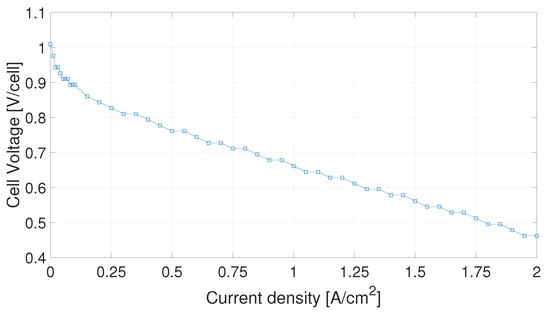
Figure 1.
PEMFC polarization curve, obtained for a cell of 25 active area at CNR-ITAE laboratories.
There are three distinct regions of a fuel cell polarization curve, corresponding to three polarization phenomena [26,27]:
- At low power densities, the cell potential drops as a result of the activation polarization, which is the energy barrier that must be overcome for the start of the chemical reaction;
- At moderate current densities, the cell potential decreases linearly with current due to ohmic losses (membrane resistance);
- At high current densities, the cell potential drop departs from the linear relationship with current density as a result of pronounced concentration polarization, due to the too low spreading of reagents inside the electrolyte for the given current level.
FC Equivalent Electric Circuit Model tries to represent the FC components and the polarization phenomena with circuit elements; thus, a resistor represents the ohmic loss of the membrane and the transfer resistances of each electrode [11], a rectifying diode is associated with the electrode polarization, and the load resistance can be a simple resistor or a more complex impedance, such as an inductor [28]. Other elements (inductor or Warburg element) make sense depending on the frequency range [11].
Dhirde et al. [13] described the behavior of the fuel cell by using Constant-Phase Elements (CPEs) and the Warburg impedance, which are now briefly analyzed.
The CPE can be described by the following impedance:
where, in general, . Looking at the frequency response of (5), it is possible to obtain different magnitude slopes and different asymptotic phase value by simply changing the fractional-order .
The Warburg impedance [29] models the diffusion process of charges inside the cell. It can be represented by the following equation:
where and represent the Warburg parameters and is the fractional-order of the impedance.
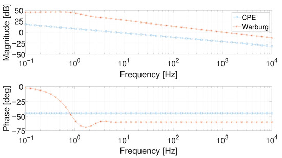
CPE and Warburg impedance responses are represented in Figure 2. The parameters of (5) and (6) for this simulation are taken from Dhirde et al. [13] to simulate their response for a typical fuel cell. More specifically, the following parameters were exploited: , , m, , and . It is possible to notice that the CPE has a magnitude slope of about dec and a phase constant of in all its frequency domain, while the Warburg impedance shows a decreasing trend in phase at very low frequencies and then it assumes a constant behavior.
These elements were exploited by Dhirde et al. [13] to realize an Equivalent Electric Circuit Model (EECM) able to simulate the fuel cell behavior (Figure 3). Two different EECMs were defined according to the value of the working point. The main circuital difference between the low- and high-current models is represented by the presence of an inductor, as in Figure 3b: such a component, indeed, allows improving the FC modeling at high frequencies. Analyzing the other components for both the EECMs of Figure 3, represents the ohmic resistance of the entire stack and and represent the ohmic resistance for the cathode and the anode of the fuel cell, respectively. The two CPEs, and , describe the behavior of the double-layer capacitors at the cathode and anode, respectively. In conclusion, the Warburg impedance allows defining, as mentioned above, the charge diffusion process. These models require a large number of parameters (10 or 11) which need to be identified for each working condition.
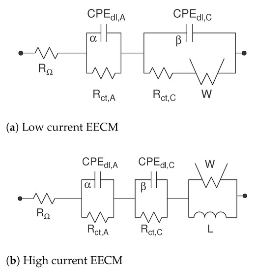
Figure 3.
The Dhirde et al. [13] equivalent electric circuit models.
Considering the current working points analyzed in the following, the high-current EECM depicted in Figure 3b (and referred to as the Dhirde et al. model) is taken as reference with the aim to validate the proposed model.
Electrochemical Impedance Spectroscopy
The Electrochemical Impedance Spectroscopy (EIS) is an effective technique for electrochemical characterization. It uses a certain number of frequencies to investigate physical and chemical phenomena in fuel cell systems.
Impedance measurements are performed by applying a sinusoidal voltage (potentiostatic method) or current (galvanostatic method) signal and measuring the corresponding dual quantity. The impedance is obtained from voltage and current ratio:
where is the real part of the fuel cell impedance and is the imaginary part (see [11]).
To obtain representative measurements of electrochemical processes, there are mainly three conditions that must be verified:
- Linearity: Typically, the current-voltage characteristic of the electrochemical systems has a non-linear shape. To consider it linear, the amplitude of the perturbation must be small, but at the same time the maximum possible to reduce the noise-to-signal level on the measurement;
- Stability: The system does not have significant changes during data acquisition. The choice of the frequency range can influence this condition;
- Causality: The system’s response is a direct consequence of the signal applied as input.
All of these considerations are taken into account in the experimental setup.
4. Experimental Setup
The experimental FC impedance measurements were carried out at the C.N.R.—Istituto di Tecnologie Avanzate per l’Energia “Nicola Giordano” of Messina using the EIS technique. The cell is a PEMFC (Proton Exchange Membrane Fuel Cell), in which the electrolyte is a proton-conducting membrane of Nafion® by Dupont. It has an active area of 25 and impedance measurements come from different load values, corresponding to different points of the polarization curve.
The polarization curve is obtained experimentally from the software of the Fuel Cell Technologies Testing Station (FCT-TS) (see Figure 4).
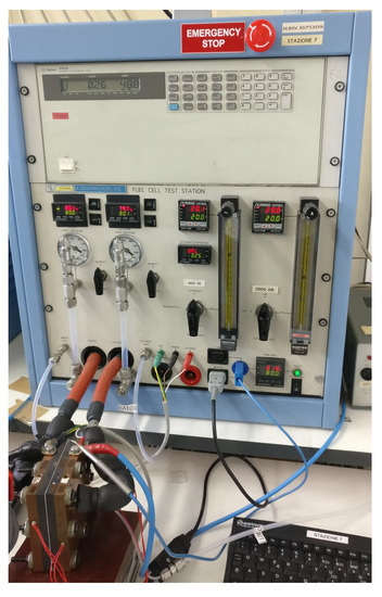
Figure 4.
Fuel Cell Technologies Testing Station (FCT-TS) used in experiments at CNT-ITAE laboratories.
The maximum current of Metrohm AUTOLAB PGSTAT302N potentiostat/galvanostat (Utrecht, The Netherlands) is 2 A. This value allows analyzing a very restricted part of the polarization curve, so the PGSTAT302N was connected with the BOOSTER20A booster (Metrohm AG, Herisau, Switzerland), which extends the maximum current up to 20 A.
The frequency range for the EIS measurement was set from to 10 , with 10 logarithmically distributed frequency values for decade, and six different points of the polarization curve, precisely for 1 A, 4 A, 5 A, 7 A, 10 A and 15 current values for the fuel cell active area of 25 are considered. The corresponding current densities are: 0.04 A cm−2, 0.16 A cm−2, 0.20 A cm−12, 0.28 A cm−2, 0.40 A cm−2 and 0.60 . Three different measurements were taken for each working point. The investigation aims to obtain a model of the process by using the obtained experimental measures. Only measurements in the range 0.1 to 1000 are considered to avoid parasitic inductive effects, which start from 1 . The obtained experimental Bode diagrams are reported in Figure 5.
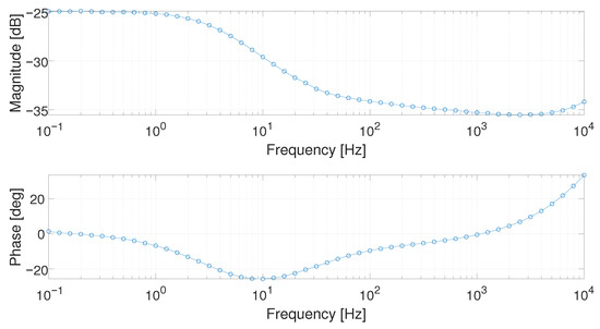
Figure 5.
Bode diagram at the working point of 1 in the frequency range [0.1; 10,000] Hz.
As shown in Figure 5, the magnitude slope is of about dB/dec, and the phase has a different slope with respect to a canonical integer-order system. Taking into account these considerations, a Fractional-Order Transfer Function (FOTF) is considered to model the frequency domain fuel cell behavior.
In the next section, the proposed model is described.
5. The Proposed Model
Analyzing the Bode diagram of Figure 5, its behavior could be described by a first-order system. The proposed FOTF is reported in (8).
where z and p represent the zero and pole of the system, and are their corresponding fractional orders, and k is a gain.
To prove the validity of the proposed model, two different approaches were adopted:
- First approach: In this scenario, the first measurement (for each working point) is identified by exploiting the model of (8) and the other two measurements are used as validation patterns in order to verify the quality of the fitting for the proposed model. Subsequently, after collecting the acquired parameters, their relation with the corresponding operation point is investigated;
- Second approach: In this scenario, every single measurement (for each working point) is identified by exploiting the model of (8) and the obtained parameters are averaged and tested to verify their goodness of fit. Subsequently, a more detailed study on the relation between parameter and the corresponding working point is performed and the proposed interpolating laws are validated.
For both proposed approaches, the identification procedure was exploited by means of Genetic Algorithms (GAs) [30,31]. The optimization algorithm was applied defining a proper cost function to minimize. This cost function is made up of a weighted sum of two different terms: the first one is the Normalized Root Mean Square Error (NRMSE) of the magnitude error between the simulated and the real magnitude responses , while the second one of the phase error , according to the following cost function ,
where evaluates the average of its argument, is the absolute-value norm, and and were empirically set in order to fit the phase behavior of the investigated working point as better as possible.
For sake of brevity, in the following only the results of two working points, i.e., 1 and 5 , are reported. The three different acquired measurements are depicted in Figure 6 and Figure 7 for the working points 1 and 5 , respectively. They are referred to as Meas #1, Meas #2, and Meas #3.
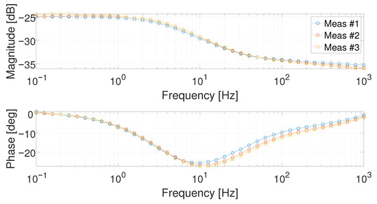
Figure 6.
Bode diagrams at 1 for the three performed measurements.
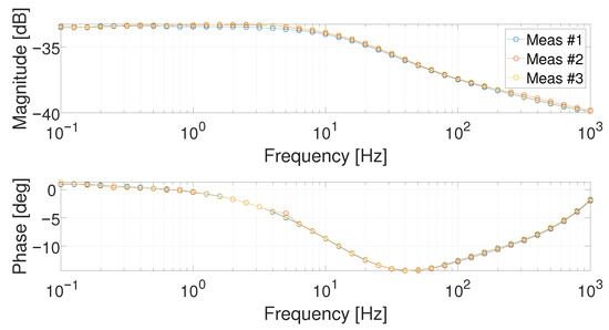
Figure 7.
Bode diagrams at 5 for the three performed measurements.
5.1. First Approach
This first approach scenario can be schematized by the flowchart in Figure 8.
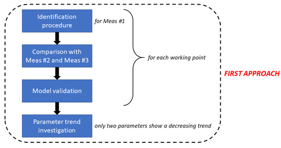
Figure 8.
First approach flowchart.
It must be pointed out that, in this approach, the GAs exploits the following setting variables:
- Number of variables: 5;
- Generation gap: 0.90;
- Number of individuals: 1000;
- Number of generations: 200;
- Precision: 10;
- Minimum domain range: ;
- Maximum domain range: .
The order of the parameters in the domain definition is the following: . In particular, both and can assume a maximum value equal to 1. In Figure 9 and Figure 10, the results of the identification procedure are depicted. It is possible to notice that the proposed model allows fitting well the investigated measurement.
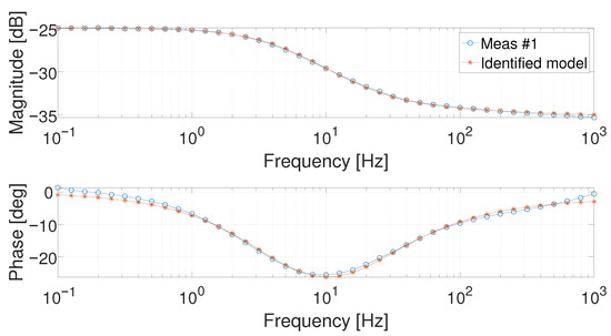
Figure 9.
Bode diagrams of the identified Meas #1 at 1 .
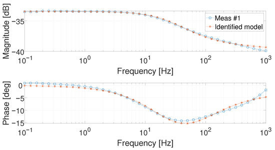
Figure 10.
Bode diagrams of the identified Meas #1 at 5 .
To validate the proposed model, the obtained system is compared with the other two measurements, taken as validation patterns. The results are reported in Figure 11 and Figure 12.
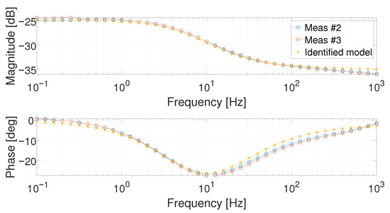
Figure 11.
Bode diagrams of the identified Meas #1 at 1 and compared with Meas #2 and Meas #3.
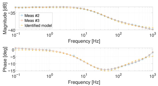
Figure 12.
Bode diagrams of the identified Meas #1 at 5 and compared with Meas #2 and Meas #3.
It is also quite evident that, for the validation pattern, the obtained models describe correctly the fuel cell behavior at the analyzed working current points. The identified parameters for each working current point were evaluated and are reported in the following (see Figure 13 and Table 1).
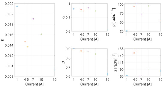
Figure 13.
Parameters plot for each analyzed working current point.

Table 1.
Identified parametervalues for (8) exploiting the first approach identification strategy.
In Figure 13, it can be observed that an interpolating curve cannot be easily obtained for k, p, or z. The parameters and show, instead, a decreasing trend as a function of the current. Even validating the suitability of the proposed model, this approach does not lead, therefore, to a single set of parameters describing the system behavior in all the working conditions.
5.2. Second Approach
In this second approach, the model tested in the previous section is analyzed in detail to avoid parameter variability and find, if they exist, suitable mathematical interpolating laws able to define parameters trend. Indeed, the parameter variability depicted in Figure 13 could depend on the performed identification procedure. In addition, in this case, this approach can be schematized by the flowchart in Figure 14.
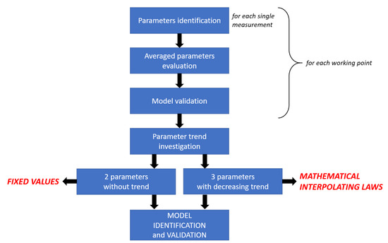
Figure 14.
Second approach flowchart.
In addition, in this case, the GAs’ parameters and the cost function to minimize were evaluated as in the previous investigation analysis. For each working point and each measurement, the parameters of (8) were identified: for the generic ith measurement of the wth working point (and the corresponding model is referred to as ). Then, their averaged values were considered: , , , , and (and the corresponding model is referred to as ). The averaged parameters of the three measurements are, hence, used to describe the fuel cell behavior for the given working point. In Figure 15 and Figure 16, the Bode diagrams of each identified measurements (i.e., , , and ), the corresponding parameter-averaged-model (i.e., ), and the averaged measurement (taken as reference) are reported. As can be observed, no relevant difference exists among , , , and .
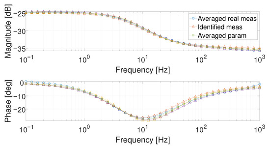
Figure 15.
Comparison of the Bode diagrams obtained with the real averaged measurement (circle marker), the model obtained on a single measurement (triangle markers, three curves), and that obtained with the averaged parameters (square marker) at 1 .
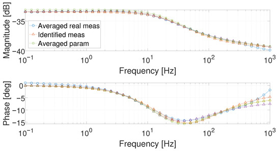
Figure 16.
Comparison of the Bode diagrams obtained with the real averaged measurement (circle marker), the model obtained on a single measurement (triangle markers, three curves), and that obtained with the averaged parameters (square marker) at 5 .
The identified parameters are collected and represented in Figure 17. A decreasing trend as a function of the current value can be observed for , , and k.
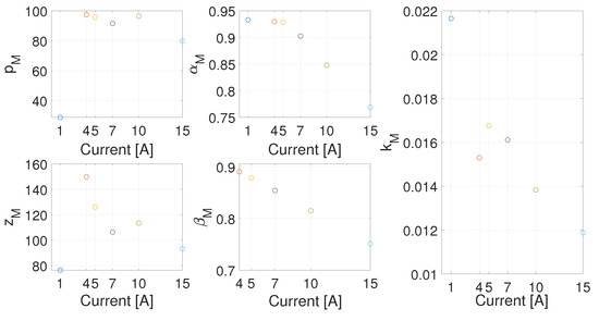
Figure 17.
Parameters plot for each working point.
As a first comparison, in Figure 18, the measured response at 10 and the estimation corresponding to 7 , 10 , and 15 , computed by using the respective set of parameters, are reported. It is possible to observe in the figure that the frequency response qualitatively corresponds to the same transfer function for each working point, with the pole and the zero moving towards the high frequency as the current increases.
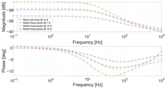
Figure 18.
Bode diagram comparison between the averaged experimental measurement at 10 (circle marked) and the averaged models at 7 , 10 and 15 , respectively.
As an example, at 1 , the magnitude changes its slope at 1 , at 5 at 10 , while at 15 the slope changes at about 50 . This behavior was noticed in all the working points.
Taking into account the above considerations, the model in (8) was again identified for each working point, fixing experimentally both the pole p and the zero z to p = 65 rad/s and z = 100 rad/s. To fit the experimental data, some adjustments are required for the corresponding fractional orders and : indeed, their range was changed to in order to move both pole and zero. The same cost function and the other GAs’ parameters were also considered in the optimization procedure. Furthermore, the working point at 7 was not considered in this second identification procedure: it is used as a validation pattern with the aim to evaluate the goodness of the interpolating laws. In Figure 19, the three parameters which have not been fixed in this new identification procedure are represented, and their values also reported in Table 2.
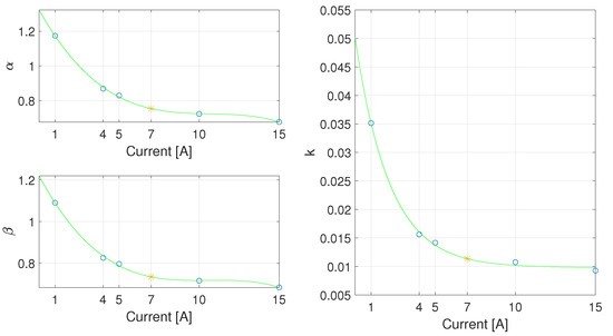
Figure 19.
Free parameter plot with p = 65 rad/s and z = 100 rad/s, the corresponding interpolation laws (green), and the fitted working point at 7 A (red).

Table 2.
Parameter values for the second identification procedure.
An important result can be outlined: all three parameters maintain the same decreasing trend as previously shown. The interpolating law can thus be easily found, as depicted in the green line of Figure 19.
The interpolating laws can be evaluated as follows:
where , , , and . The norm of the residuals is equal to .
where , , , and . The norm of the residuals is equal to .
where , , and . The norm of the residuals is equal to .
The results of the identification procedure are depicted in Figure 20 and Figure 21. The Bode diagram of the model with the interpolated parameters for 7 A is reported in Figure 22: the results are close to the real data and the identified model obtained from the same working point.
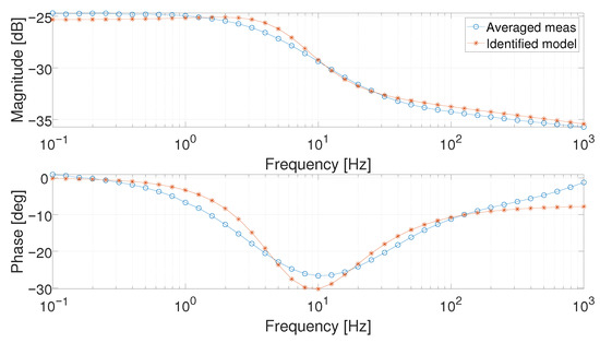
Figure 20.
Bode diagram of the averaged measurement (circle marked) and identified model (asterisk marked) at 1 .
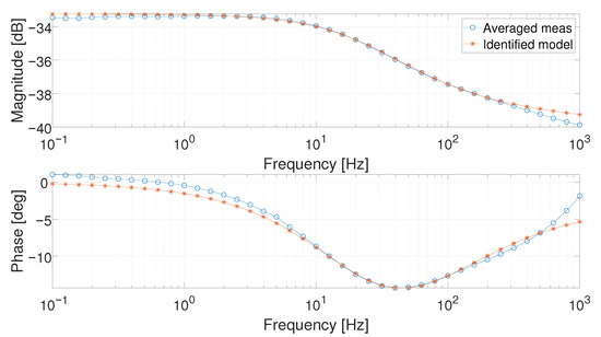
Figure 21.
Bode diagram of the averaged measurement (circle marked) and identified model (asterisk marked) at 5 .
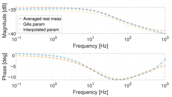
Figure 22.
Bode diagram of the averaged real measurements (circle marked), of the identified model (asterisk marked) and the model with the interpolated parameters at 7 .
6. Model Comparison
In this section, as a further comparison to support the decision of using the proposed equivalent system in (8), the same measurements are used to identify the parameters of the model proposed by Dhirde [13], reported in Section 2. In particular, the high-current model was considered because the current density of the analyzed fuel cell belongs to the high-current range of the referenced model.
First, exploiting the same optimization procedure described in the previous sections, the high-current Dhirde et al. EECM was investigated by identifying its parameters for each working point, as depicted in Figure 23.
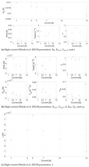
Figure 23.
The high-Current Dhirde et al. EECM parameters.
It is possible to observe that only five parameters (i.e., , , , , and ) follow a well-defined trend, whereas the others are scattered for the different current values. In Figure 24, the model output computed with the parameters obtained for 5 is compared with the fuel cell response at 1 and 15 . In the figure, it can be observed that the parameter obtained for a given working point cannot be adopted for the others. The model is able to give a good fit, but a different set of parameters should be used for each working point. Some attempts were made to find a set of parameters able to give a good approximation on all the considered working points or some interpolating laws without obtaining satisfactory results.
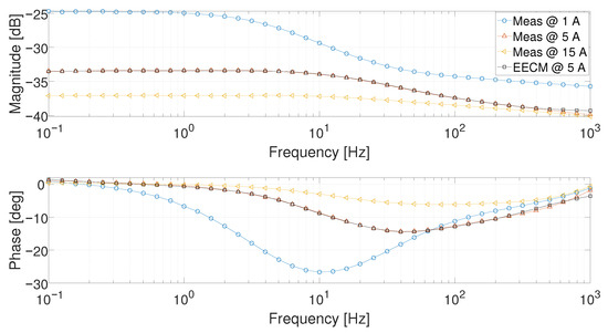
Figure 24.
Bode diagrams of the averaged real measurements at 1 , 5 , and 15 and the EECM evaluated at the current working point of 5 .
As stated in the Introduction, the main aim of our work is to find a suitable approximated model which is able to cover all the working conditions with a low number of parameters, computed as a function of the current. The quality of the approximation should therefore be evaluated. A comparison between the output estimation obtained with the Dhirde at al. [13] EECM for two working points (i.e., 1 and 5 ), by using the two corresponding set of parameters, is reported along with the estimation obtained by using our model in Figure 25 and Figure 26. Looking at the 1 working point, it is possible to notice that the Dhirde et al. [13] model better fits the real data compared to our model. A smaller difference between the two models can be observed at 5 . As a general result, a better agreement is obtained by using our model for intermediate values of the current.
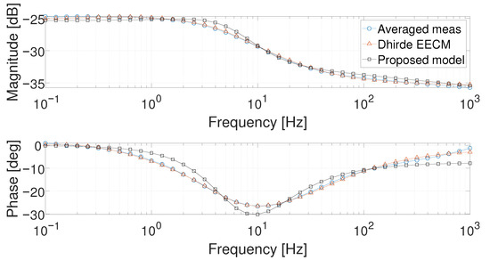
Figure 25.
Bode diagram of the averaged measurement (circle marked), the Dhirde et al. model (triangle marked), and the proposed model of (8) (squared marked) at 1 .
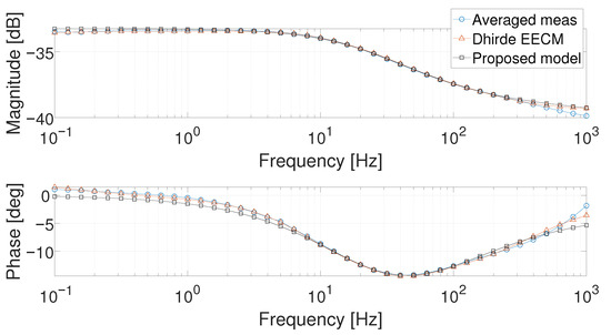
Figure 26.
Bode diagram of the averaged measurement (circle marked), the Dhirde et al. model (triangle marked), and the proposed model of (8) (squared marked) at 5 .
The quality of the approximation is evaluated by using the Mean Absolute Error (MAE), as reported in Table 3. MAE values under dB and 1 deg were considered acceptable. The MAE is calculated for each current i as
where: n is the number of the element of the impedance vector , is the magnitude or the phase of the Bode diagram of the averaged measurement, and is the magnitude or the phase of the Bode diagram of the FOTF or Dhirde EECM Model.

As shown in the table, only the MAE value computed for the phase at 1 exceeds the fixed threshold.
Summarizing all the aforementioned considerations and results, the model of (8) can be considered as a good approximated model, able to describe fuel cell behavior for all the currents belonging to the interval 1 –15 , without the need to estimate a different set of parameters for each working point.
7. Conclusions
In this study, a new model was proposed to describe the behavior of a PEM fuel cell for a set of currents, by means of a single Fractional-Order Transfer Function. The proposed model exploits only five parameters; two parameters are fixed, while the others can be mathematically computed as a function of the current. The FOTF was identified by using a set of EIS experimental measurements taken at the laboratories of C.N.R.—I.T.A.E. of Messina, on a 25 active area PEMFC. Genetic algorithms were used to identify the FOTF parameters for each working point. As a second step, an approximated model was searched for. To this aim, two of the five parameters were fixed and an interpolation function was designed for the remaining three parameters, as a function of the current value. The quality of the approximation was evaluated both against the experimental measurements and the simulations of a model reported in the literature. Further research activities will be devoted to finding an Equivalent Electric Circuit Model based on the proposed FOTF. In addition, new instrumentation will be used to measure currents higher than 20 A, extending the validity range of the proposed approach.
Author Contributions
Conceptualization, R.C., F.M., E.M., E.P. and M.G.X.; methodology, R.C., F.M., E.M., E.P. and M.G.X.; software, E.M. and E.P.; writing—original draft preparation, R.C., F.M., E.M., E.P. and M.G.X.; writing—review and editing, R.C., F.M., E.M., E.P. and M.G.X. All authors have read and agreed to the published version of the manuscript.
Funding
This research received no external funding.
Conflicts of Interest
The authors declare no conflict of interest.
References
- Niaz, S.; Manzoor, T.; Pandith, A.H. Hydrogen storage: Materials, methods and perspectives. Renew. Sustain. Energy Rev. 2015, 50, 457–469. [Google Scholar] [CrossRef]
- Sherif, S.A.; Barbir, F.; Veziroglu, T.N. Wind energy and the hydrogen economy-review of the technology. Sol. Energy 2005, 78, 647–660. [Google Scholar] [CrossRef]
- Bockris, J.O.; Veziroglu, T.N. A Solar-Hydrogen Energy System for Environmental Compatibility. Environ. Conserv. 1985, 12, 105–118. [Google Scholar] [CrossRef]
- Danzer, M.A.; Hofer, E.P. Analysis of the electrochemical behaviour of polymer electrolyte fuel cells using simple impedance models. J. Power Sources 2009, 190, 25–33. [Google Scholar] [CrossRef]
- Galeotti, M.; Cinà, L.; Giammanco, C.; Cordiner, S.; Di Carlo, A. Performance analysis and SOH (state of health) evaluation of lithium polymer batteries through electrochemical impedance spectroscopy. Energy 2015, 89, 678–686. [Google Scholar] [CrossRef]
- Sun, H.; Yu, M.; Li, Q.; Zhuang, K.; Li, J.; Almheiri, S.; Zhang, X. Characteristics of charge/discharge and alternating current impedance in all-vanadium redox flow batteries. Energy 2019, 168, 693–701. [Google Scholar] [CrossRef]
- Huaxin, L.; Jian, C.; Chizhou, Y.; Hao, L. On-line fault diagnosis for proton exchange membrane fuel cells based on a fast electrochemical impedance spectroscopy measurement. J. Power Sources 2019, 430, 233–243. [Google Scholar]
- Zhiani, M.; Majidi, S.; Silva, V.B.; Gharibi, H. Comparison of the performance and EIS (electrochemical impedance spectroscopy) response of an activated PEMFC (proton exchange membrane fuel cell) under low and high thermal and pressure stresses. Energy 2016, 97, 560–567. [Google Scholar] [CrossRef]
- Gomadam, P.M.; Weidner, J.W. Analysis of electrochemical impedance spectroscopy in proton exchange membrane fuel cells. Int. J. Energy Res. 2005, 29, 1133–1151. [Google Scholar] [CrossRef]
- Shi, J.; Xue, X. Mechanistic model based multi-impedance curve-fitting approach for solid oxide fuel cells. J. Electroanal. Chem. 2011, 661, 150–156. [Google Scholar] [CrossRef]
- Ben Yahia, M.S.; Allagui, H.; Bouaicha, A.; Mami, A. Fuel cell impedance model parameters optimization using a genetic algorithm. Int. J. Electr. Comput. Eng. 2017, 7, 184–193. [Google Scholar] [CrossRef][Green Version]
- Pan, R.; Yang, D.; Wang, Y.; Chen, Z. Health degradation assessment of proton exchange membrane fuel cell based on an analytical equivalent circuit model. Energy 2020, 207, 118185. [Google Scholar] [CrossRef]
- Dhirde, A.M.; Dale, N.V.; Salehfar, H.; Mann, M.D.; Han, T.H. Equivalent electric circuit modeling and performance analysis of a PEM fuel cell stack using impedance spectroscopy. IEEE Trans. Energy Convers. 2010, 25, 778–786. [Google Scholar] [CrossRef]
- Oldham, K.B.; Spanier, J. The Fractional Calculus: Theory and Applications of Differentiation and Integration to Arbitrary Order; Academic press: New York, NY, USA, 2006. [Google Scholar]
- Atangana, A.; Baleanu, D. New Fractional Derivatives with Nonlocal and Non-Singular Kernel: Theory and Application to Heat Transfer Model. Therm. Sci. 2016, 20, 763–769. [Google Scholar] [CrossRef]
- Caputo, M.; Fabrizio, M. A new Definition of Fractional Derivative without Singular Kernel. Prog. Fract. Differ. Appl. 2015, 1, 73–85. [Google Scholar]
- Sabatier, J.; Farges, C.; Trigeassou, J. Fractional systems state space description: Some wrong ideas and proposed solutions. J. Vib. Control. 2014, 20, 1076–1084. [Google Scholar] [CrossRef]
- Sun, H.; Zhang, Y.; Baleanu, D.; Chen, W.; Chen, Y. A new collection of real world applications of fractional calculus in science and engineering. Commun. Nonlinear Sci. Numer. Simul. 2018, 64, 213–231. [Google Scholar] [CrossRef]
- Caponetto, R.; Machado, J.T.; Murgano, E.; Xibilia, M.G. Model Order Reduction: A Comparison between Integer and Non-Integer Order Systems Approaches. Entropy 2019, 21, 876. [Google Scholar] [CrossRef]
- Ardjal, A.; Merabet, A.; Bettayeb, M.; Mansouri, R.; Labib, L. Design and implementation of a fractional nonlinear synergetic controller for generator and grid converters of wind energy conversion system. Energy 2019, 186, 115861. [Google Scholar] [CrossRef]
- Tarasov, V.; Tarasova, V. Criterion of Existence of Power-Law Memory for Economic Processes. Entropy 2018, 20, 414. [Google Scholar] [CrossRef]
- Caponetto, R.; Pasquale, G.D.; Graziani, S.; Murgano, E.; Pollicino, A. Realization of green fractional order devices by using bacterial cellulose. AEU Int. J. Electron. Commun. 2019, 112, 246–254. [Google Scholar] [CrossRef]
- Vastarouchas, C.; Tsirimokou, G.; Freeborn, T.; Psychalinos, C. Emulation of an electrical-analogue of a fractional order human respiratory mechanical impedance model using OTA topologies. AEU Int. J. Electron. Commun. 2017, 78, 201–208. [Google Scholar] [CrossRef]
- Sabatier, J. Fractional Order Models for Electrochemical Devices. In Fractional Dynamics; Cattani, C., Srivastava, H.M., Yang, X.J., Eds.; De Gruyter: Warsaw, Poland, 2016; Chapter 9; pp. 141–160. [Google Scholar]
- Zhu, Q.; Xu, M.; Liu, W.; Zheng, M. A state of charge estimation method for lithium-ion batteries based on fractional order adaptive extended kalman filter. Energy 2019, 187, 115880. [Google Scholar] [CrossRef]
- Polarization Curve. Available online: https://www.fuelcellstore.com/blog-section/polarization-curves (accessed on 3 February 2021).
- Liga, R. Caratterizzazione e modellistica di uno stack di celle a membrana polimerica (PEM) per sistemi di propulsione per automotive. Ph.D. Thesis, University of Palermo, Palermo, Italy, 2013. [Google Scholar]
- Benziger, J.B.; Satterfield, M.B.; Hogarth, W.H.; Nehlsen, J.P.; Kevrekidis, I.G. The power performance curve for engineering analysis of fuel cells. J. Power Sources 2006, 155, 272–285. [Google Scholar] [CrossRef]
- Bard, A.J.; Faulkner, L.R. Electrochemical Methods: Fundamentals and Applications, 2nd ed.; Wiley: New York, NY, USA, 2000; Chapter 10. [Google Scholar]
- Goldberg, D. Genetic Algorithms in Search, Optimization, and Machine Learning; Addison-Wesley Professional: Boston, MA, USA, 1989. [Google Scholar]
- Chipperfield, A.J.; Fleming, P.J.; Fonseca, C.M. Genetic Algorithm Tools for Control Systems Engineering. In Proceedings of the Adaptive Computing in Engineering Design and Control, Plymouth, UK, 21–22 September 1994; Plymouth Engineering Design Centre: Plymouth, UK, 1994; pp. 128–133. [Google Scholar]
Publisher’s Note: MDPI stays neutral with regard to jurisdictional claims in published maps and institutional affiliations. |
© 2021 by the authors. Licensee MDPI, Basel, Switzerland. This article is an open access article distributed under the terms and conditions of the Creative Commons Attribution (CC BY) license (http://creativecommons.org/licenses/by/4.0/).
