Article

Fractal Metamaterial Beams: Tuning Dynamic Stiffness and Vibration Attenuation
by
Jonathan A. Sotomayor-del-Moral
1,2,
Juan B. Pascual-Francisco
2,*,
Orlando Susarrey-Huerta
3,*,
Leonardo I. Farfan-Cabrera
4,
Víctor Estrada-Manzo
2 and
Enrique Cuan-Urquizo
4,5
1
Departamento de Mecatrónica, Universidad Tecnológica de la Zona Metropolitana del Valle de México, Blvd. Miguel Hidalgo Y Costilla, Los Héroes, Tizayuca 43816, Hidalgo, Mexico
2
Departamento de Mecatrónica, Universidad Politécnica de Pachuca, Carretera Pachuca-Cd. Sahagún Km. 20, Ex-Hacienda de Santa Barbara, Zempoala 43830, Hidalgo, Mexico
3
Sección de Estudios de Posgrado, Escuela Superior de Ingeniería Mecánica y Eléctrica, Instituto Politécnico Nacional, Unidad Zacatenco, Col. Lindavista, Ciudad de México 07738, Mexico
4
Escuela de Ingeniería y Ciencias, Tecnologico de Monterrey, Ave. Eugenio Garza Sada 2501, Monterrey 64849, Nuevo León, Mexico
5
AI for Manufacturing and Supply Chain Institute (AIMS), Tecnologico de Monterrey, Monterrey 67000, Nuevo León, Mexico
*
Authors to whom correspondence should be addressed.
Fractal Fract. 2026, 10(7), 435; https://doi.org/10.3390/fractalfract10070435
Submission received: 12 May 2026 / Revised: 19 June 2026 / Accepted: 22 June 2026 / Published: 26 June 2026
(This article belongs to the Special Issue Fractal and Fractional Approaches in Interdisciplinary Mechanics)

Abstract

Despite recent advances in metamaterials, experimental studies addressing the dynamic behavior of waveguide-type fractals manufactured by means of additive manufacturing remain scarce, limiting understanding of their performance in real-world vibration control. This study investigates the dynamic behavior of fractal waveguide beams based on Sierpinski geometry through combined experimental and analytical approaches. Beams with iterations i = 0–3 were fabricated via stereolithography and tested under a doubly clamped configuration subjected to harmonic excitation. The dynamic response was captured using an accelerometer and analyzed in both time and frequency domains using Fast Fourier Transform. A single-degree-of-freedom mass–spring model was employed to estimate dynamic stiffness and validate experimental results. The findings reveal that fractal geometry significantly influences vibrational behavior, producing a nonlinear and non-monotonic evolution of stiffness and energy dissipation. The highest-order fractal beam exhibited the greatest vibration attenuation and resonance frequency (27.2 Hz), despite having the lowest effective mass, demonstrating an optimized stiffness-to-mass ratio. Spectral area analyses confirmed that energy dissipation increases with fractal complexity, enabling identification of transitions between stiffness- and inertia-dominated regimes. By identifying these regimes, this work provides a framework for engineering lightweight, adaptive structures for advanced vibration attenuation and tunable mechanical vibration control applications.

1. Introduction

Structural and mechanical elements, such as buildings, bridges, vehicles, and machinery, are exposed to vibrations generated by the propagation of mechanical waves in elastic media [1,2]. These vibrations could cause structural damage, functional failures, or operational discomfort, which negatively affects the performance, efficiency, and lifespan of such systems [3,4]. To mitigate these effects, various vibration control systems have been developed. The most efficient have been achieved by using viscoelastic materials that are known for their ability to dissipate energy through internal friction [5,6]. However, viscoelastic materials present important limitations, such as low efficiency in the low-frequency range, a poorly adaptable response to different load and frequency conditions, and a high dependence on properties that may vary over time and temperature [7,8,9]. These limitations have motivated the search for more versatile and efficient solutions, among which metamaterials stand out as promising candidates for vibration absorption and control [10,11,12].
Metamaterials are artificial materials designed to exhibit physical properties not found in conventional materials, for example, tunable mechanical properties [13], negative refractive index [14], negative magnetic permeability, or negative Poisson’s ratio [15,16]. These properties emerge from their internal architecture, whether periodic or non-periodic structural patterns, rather than their chemical composition [17]. Among mechanical metamaterials, fractal structures are well known and highly appreciated for their self-similar structure, which repeats at different scales [18,19]. This feature facilitates multiple resonance modes [20], which imply an improvement of their ability to absorb energy and vibrations under a wide range of frequencies and amplitudes [21,22]. Nonetheless, to evaluate their effectiveness and determine their effective mechanical properties, it is necessary to conduct experimental tests and numerical simulations to firmly establish the corresponding frequency range in which each type of metamaterials offers better performance [23,24].
Several studies have leveraged simulations to analyze the dynamic properties of mechanical metamaterials [25,26], illustrating how fractal-cut architectures fundamentally alter effective elastic constants and structural responses compared to plain Euclidean materials. This body of research includes experimental characterizations of elastic structures [27] and the development of 3D-printed fractal prototypes fabricated from polymeric materials [28,29]. These studies found that architecture structures have significant mechanical advantages in terms of dynamical behavior. Moreover, earlier theoretical investigations have been carried out on the dynamic and mechanical behavior of structures with fractal geometry [30,31,32], where it was found that the fractal configuration modulates the responses of the material. According to De La Rosa Silva et al. [33], 3D-printed fractal structures, particularly those based on iterations of the Sierpinski set and manufactured with materials such as TPU, offer significant advantages in structural efficiency and vibrational behavior, at least in simulation. Quasi-static compression tests and finite element simulations showed that a higher fractal order improves energy dissipation capacity without increasing mass, while maintaining comparable stiffness. Stress concentration zones were mainly located on the internal diagonal edges, suggesting opportunities for geometric optimization. The study concludes that these modular geometries allow for lightweight, material-efficient, and adaptable designs for functional applications such as support components or dampers. In another study, Pascual-Francisco et al. [34] experimentally investigated the creep properties of 3D-printed viscoelastic structures using a fourth-iteration Sierpinski carpet-type fractal geometry. The samples were manufactured by means of photopolymerization with flexible resin (Resione F69), highlighting 3D printing as a key technique for replicating highly porous and complex geometries. Creep tests under tension at different temperatures and stress levels revealed that the fractal structure reduces stiffness and promotes a more viscous behavior compared to the solid material. Additionally, an increase in the Poisson’s ratio was observed in the creep state, indicating greater structural adaptability, and it was demonstrated that the fractal geometry not only modifies mechanical behavior but also enhances the conformability and energy efficiency of the material in long-term applications. Despite these recent advances, experimental studies addressing the dynamic behavior of waveguide-type fractals manufactured by means of additive manufacturing technologies are still very scarce [35].
In this context, the present work aims to contribute to the study of the dynamic behavior and vibration absorption capacity of waveguide-type fractal metamaterials, through the design and analysis of doubly supported beams with cross-sections based on the Sierpinski set in its first three iterations. The structures are modeled using Computer-Aided Design (CAD) tools and manufactured using stereolithography 3D printing technology. The dynamic response of the beams is analyzed using a classical mass–spring model; the experimentally obtained responses are compared with the dynamic stiffness of the system. The results show a high concordance between the theoretical model and the experimental data, validating the methodology used and establishing a solid basis for the characterization of fractal structures as vibration attenuators. This research provides new evidence on the potential of fractal metamaterials in advanced mechanical applications, establishing future research aimed at designing more efficient and adaptive structural systems.

2. Materials and Methods

2.1. Design and Fabrication of Fractal Geometries

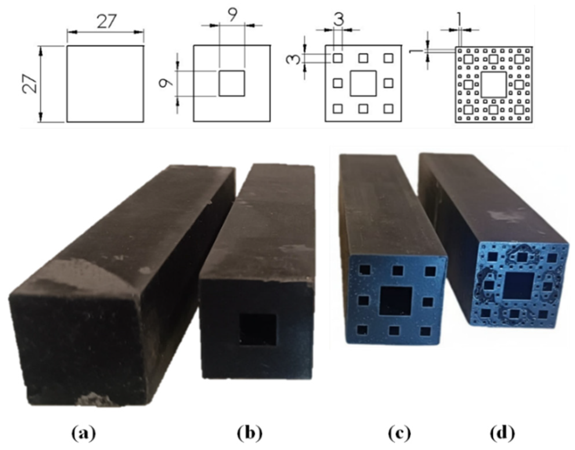
For the design of the waveguide-type beams, the Euclidean geometry of the Sierpinski set was used, considering up to the third iteration. The cross-sectional architecture is defined by the recursive generation of the square Sierpinski carpet, whereby each sub element is subdivided into a 3 × 3 grid and the central square is removed. The design rule establishes that the void side length at each iteration i is given by L v o i d , i = 27 3 i . Thus, the resulting void dimensions are 9 mm (i = 1), 3 mm (i = 2), and 1 mm (i = 3), as noted in Figure 1. The models of the samples were designed with the software SolidWorks (Version 2025); then they were converted to .STL files to facilitate the 3D printing. Figure 1 shows the dimensions of the cross-section of the studied beams. The fabrication of these structures was carried out by a 3D stereolithography printing, using F69 resin from Resione® (Resione, Dongguan, China) and a Creality® R6 printer (Shenzhen Creality 3D Technology Co., Ltd., Shenzhen, China). This technology allows reproducing a high-fidelity fractal geometry, this is essential for precise experimental characterization of their structural properties. The Euclidean and fractal samples were printed at a layer thickness of 50 μm and post-cured during 2 h at room temperature. The F69 resin was selected due to its favorable mechanical properties, such as its flexibility, which is especially useful for studying dynamic phenomena in structures subjected to vibrations. This material has a density of 1079 kg/m3 and an elastic modulus of 2 MPa, tensile strength of 4.87 MPa and a Poisson’s ratio of 0.47 [34].
Considering the printing area limitations of the equipment, the maximum beam length was set to 15 cm. Figure 1 illustrates the printed structures, highlighting the high geometric precision and surface quality achieved through the additive manufacturing process.

2.2. Experimental Setup for Dynamic Responses

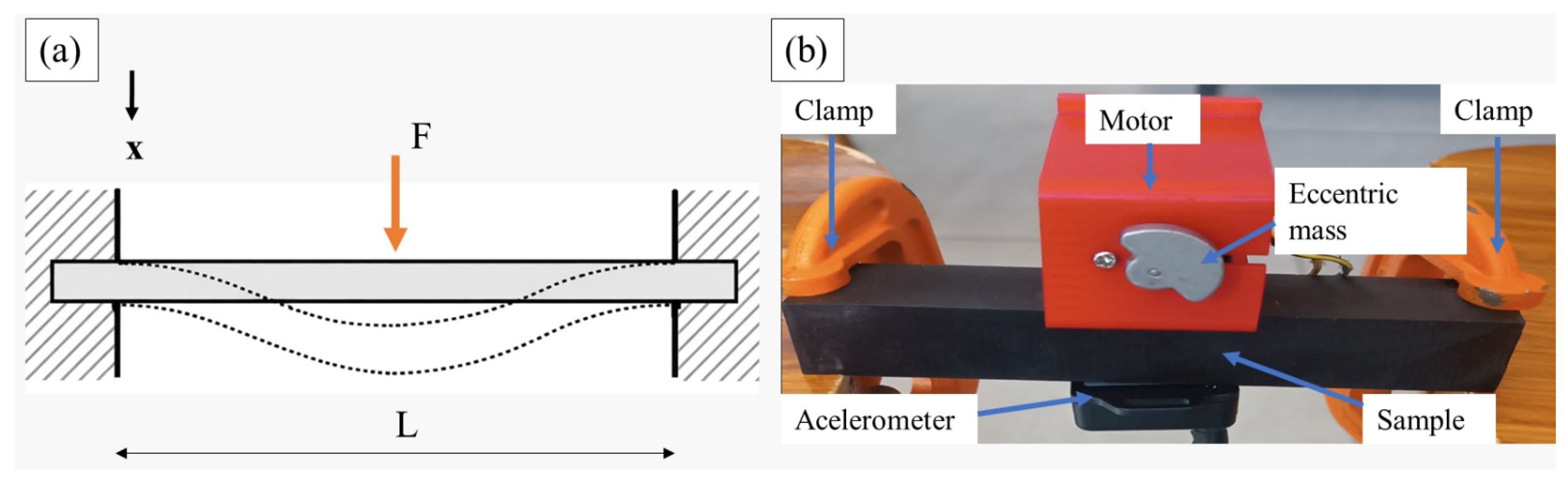
To understand the dynamic behavior of structures subjected to vibrations, it is essential to develop a precise experimental setup that allows capturing and analyzing their structural response. In this study, a doubly clamped beam (Figure 2a) loaded at its midspan is considered. Figure 2b shows the experimental setup implemented in this study.
The excitation system used in this study consists of a vibration motor designed to induce controlled vibrations in the tested beams. This motor has a maximum operating frequency of 80 Hz and is equipped with two eccentric masses (one at each end of the shaft) of 10 g each, specifically designed for vibration generation. The mass of the motor is 50 g. Thus, the total mass of the excitation system used is 70 g. This configuration ensures an adequate application of a punctual normal force, allowing for precise characterization of the dynamic excitation transmitted to the mid-span of the beam, as shown in Figure 2, ensuring that only a single vibration mode is induced in the beam being doubly clamped. Additionally, the motor is operated using a pulse-width modulation (PWM) system, enabling precise frequency control from 1 to 80 Hz. Thanks to this control, a complete frequency sweep within this range can be performed, ensuring reproducible and reliable experimental conditions for evaluating the dynamic behavior of the studied structures.
The WithMotion® accelerometer sensor (WitMotion Shenzhen Co., Ltd. Shenzhen, China) was selected for its advanced measurement capability in the three Cartesian axes (x, y, z), providing essential data on velocity, acceleration, displacement, and frequency. Its high precision and real-time capture permit the characterization of the dynamic response of the doubly clamped beam under external excitations, correlating the experimental results with theoretical models. The purpose of this setup is to validate the mathematical model that describes the vibration response of the doubly clamped beam with the traditional mass–spring model. The data obtained through the accelerometer will be processed with Fourier transforms, which will allow identifying key patterns in frequency, vibration amplitude, and structural stability. This approach provides a solid basis for future research on adaptable stiffness control and material optimization in dynamic environments.

2.3. Determination of the Theoretical Stiffness

This section addresses the determination of the theoretical stiffness ( K ) of the fractal beams. Based on the classical deflection equation for the doubly clamped beam configuration, the stiffness is calculated as follows:
K   =   192 EI L 3 ,
where E is the elastic modulus of the material, I is the moment of inertia of the cross section, calculated specifically for the fractal geometry of each beam (Table 1), and L is the length of the beam (150 mm). This approach enables to obtain a fundamental parameter that characterizes the structure’s ability to withstand deformations under static load, which is essential for comparing the structural response of the different fractal configurations and validating the experimental results.
The precise determination of stiffness requires calculating the moment of inertia I , which depends on the complex geometry of the cross section of each fractal beam. Once the geometric parameters and the E value are obtained, they are substituted into Equation (1) for each case studied, thus allowing comparison of the stiffness between the different fractal iterations and the reference Euclidean beam.
By decomposing the cross section of the beams into geometric subelements (shown in Figure 1) and applying the parallel axis theorem, the moments of inertia I 0 , I 1 , I 2 and I 3 corresponding to the Euclidean beam, first-iteration fractal beam, second-iteration fractal beam, and third-iteration fractal beam, respectively, are calculated using the following expressions:
I 0 = h 4 12
I 1 = h 4 12 h 3 4 12
I 2 = h 4 12 h 3 4 12 6 h 9 4 12 + A 2 D 2 x 2 2 h 9 4 12
I 3 = h 4 12 h 3 4 12 6 h 9 4 12 + A 2 D 2 x 2 2 h 9 4 12
18 h 27 4 12 + A 3 D 3 x 2 18 h 27 4 12 + A 3 D 4 x 2 12 h 27 4 12 + A 3 D 5 x 2
where h is the width of the reference Euclidean beam and serves as the basis for generating the width of the fractal subelements h 3 , h 9 , h 27 . The terms of the form h 4 12 represent the centroidal moments of inertia of each subelement, while the numerical coefficients (6, 2, 18, 12) indicate the number of substructures generated in each fractal iteration. A 2 and A 3 represent the areas of the small voids in the second and third iterations, respectively, and D 2 x , D 3 x , D 4 x and D 5 x represent the distances from the general centroid to the centroid of each group of squares in the second and third iteration. In this way, the moments of inertia I 0 , I 1 , I 2 and I 3 reflect the progressive removal of material and the geometric redistribution characteristic of each fractal iteration.

2.4. Determination of the Effective or Experimental Stiffness

The natural frequency of the doubly fixed beam is determined experimentally by applying a programmed frequency sweep with the vibrating motor, using a PWM system from 1 Hz to 80 Hz. During the experimental procedure, the vibration response generated in the beam from the applied excitation is recorded. To analyze these data, the FFT is used to obtain the spectral components, enabling identification of the magnitude of the different dominant frequencies. The natural frequency of the beam is determined by identifying the frequency value in the FFT spectrum that shows the maximum magnitude. This peak corresponds to the resonance point, where the structure responds with the greatest amplitude to the applied excitation. Once the natural frequency is identified from the experiment, it is possible to estimate the effective stiffness ( K f ) of the system using the following relation:
K f = m ω n 2 ,
where ω n is the natural frequency and m is the total mass of the system (the sum of the mass of the beam and the mass of the excitation system).
In the SDOF model, the motor is represented as a lumped mass located at the beam mid-span, corresponding to the point of maximum displacement in the fundamental vibration mode. Under this assumption, the beam and the excitation system (motor and eccentric weights) are considered to oscillate together as a single dynamic unit. Therefore, the total mass m in Equation (6) is defined as the combined mass of the beam and the excitation system, allowing the dominant inertial behavior of the structure to be accurately represented.
In this way, by having the experimentally obtained effective stiffness values and the theoretical values calculated from the geometric and material properties of each beam, a direct comparison between both results can be made. This comparison allows for the evaluation of the accuracy of the mathematical models used and verifies the correspondence between theory and practice, identifying possible discrepancies attributable to factors such as manufacturing imperfections, effects of the fractal geometry, or limitations of the experimental setup.

2.5. Determination of the Dynamic Stiffness

Although a doubly fixed beam is, in principle, a continuous system with an infinite number of vibration modes, in the present study, a single degree of freedom (SDOF) model is adopted to describe its dynamic behavior. This choice is based on modal analysis principles and the nature of the excitation used in the experimental setup described in Section 2.2.
From a theoretical point of view, the response of a continuous structure can be decomposed into the superposition of its own modes. However, when the external excitation has a limited spectral content and acts within a narrow frequency range, as is the case with the unbalanced motor used in the experiment, the energy supplied to the system is predominantly concentrated in the fundamental mode. In double-fixed beams, this first mode exhibits a significantly lower frequency than the higher modes, causing the contribution from higher-order modes to be negligible within the operating interval. Under these conditions, the overall dynamics are governed by a single dominant mode, which allows the system to be represented by an SDOF model without significant loss of accuracy as supported in Section 3.3. Additionally, using a multiple degrees of freedom (MDOF) model would require identifying several modal masses and stiffnesses, as well as characterizing the interaction between modes. These parameters cannot be reliably determined from the type of measurement obtained with the sensor mounted on the beam, since the experiment does not appreciably excite the higher modes. Including them in the model would introduce unnecessary uncertainty and would not provide relevant information for the dynamic phenomenon observed.
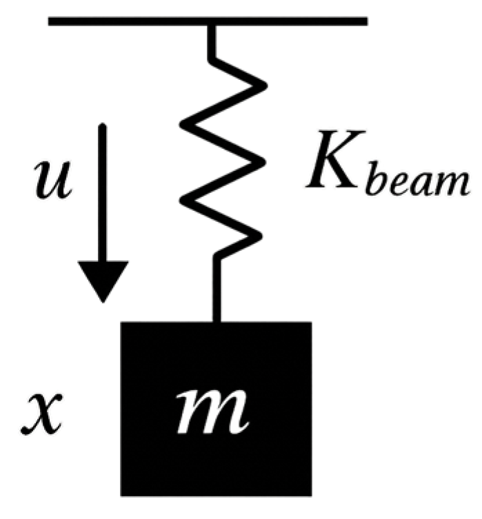
For these reasons, the SDOF model shown in Figure 3 constitutes an appropriate representation of the system. In this representation, the stiffness K f = K b e a m captures the global equivalent stiffness of the doubly fixed beam, while the mass m represents the sum of the mass of the beam and the actuator. This formulation allows for a direct connection between the experimental response and the system’s equation of motion, facilitating physical interpretation and validation of the theoretical model, neglecting the complexities inherent in an MDOF approach.
The variable x in Figure 3 represents the displacement of the system (which simulates the deflection at the mid-span of the beam in the experimental setup), while u denotes the external force applied to the system, responsible for generating the dynamic excitation. The analytical model for this system is given by the following second-order differential equation:
m x ¨ + K b e a m x = u ,
where x is the displacement and x ¨ is the acceleration.
Within the framework of classical physics, Equation (7) represents the model that describes the motion of a system subjected to various load conditions. This formulation is widely accepted and used to calculate and analyze the displacements, velocities, and accelerations of physical bodies subjected to static, harmonic, and even, in more complex cases, random loads. This equation is based on Newton’s second law and considers elastic behavior according to Hooke’s law. However, if a forced excitation is introduced, such as the force generated by a rotating motor, the dynamics of the system are significantly altered, requiring the calculation of dynamic stiffness, as it is necessary to describe the system’s response. When considering an external dynamic force, the equation of motion is rearranged, allowing the total force applied to the system to be expressed as follows:
u = K b e a m x m ω 2 x
By dividing Equation (8) by the displacement, the expression for the dynamic stiffness is written as:
K D = u x = K b e a m m ω 2
It can be observed that the dynamic stiffness K D , is the sum of two contributions:
  • K b e a m : the effective stiffness of the system, which is associated with the spring or elastic element.
  • m ω 2 : an additional term that reflects the effect of inertia due to the mass of the system and the angular frequency given by the motor ( ω ).
This expression allows us to interpret how the structure appears to be stiffer or more flexible depending on the frequency at which it is excited. Its behavior does not describe a physical stiffness of the material, but an apparent stiffness that simultaneously integrates the effects of elasticity and inertia.
When the excitation frequency is lower than the natural frequency of the system, the inertial term m ω 2 is small compared to the effective stiffness. In this regime, the response is dominated by the elasticity of the structure, and therefore, the dynamic stiffness remains positive. This implies that the force and displacement are in phase, which is a typical characteristic of the stiffness-controlled region.
As the excitation frequency approaches the natural frequency, the inertial term increase until it equals the effective stiffness. At this point, the dynamic stiffness is vanished:
K D ω n = 0
which corresponds to the condition of resonance, where the structure offers minimal opposition to the excitation and the response amplitude reaches its theoretical maximum.
For frequencies higher than the natural frequency, the inertial term m ω 2 surpasses the effective stiffness, resulting in negative values of dynamic stiffness. This result does not imply that the structure possesses a physically negative stiffness, but rather that the response is dominated by the inertia. In this regime, force and displacement are out-of-phase, which is characteristic of the mass-controlled region. Negative dynamic stiffness is therefore a mathematical manifestation of phase inversion and the predominance of inertial behavior at high frequencies. In summary, the change in the sign of dynamic stiffness constitutes a fundamental tool for interpreting the transition between stiffness-dominated, resonance, and inertia-dominated regimes, providing a theoretical framework for the analysis of vibration systems modeled as a single degree of freedom. This concept is essential because it allows us to understand how the system’s behavior varies when subjected to dynamic loads, especially when the excitation frequency approaches the natural frequency of the system ( ω n ) , a condition in which resonance phenomena may occur.

2.6. Evaluation of the Vibration Absorption in Fractal Beams

The characterization of the vibration absorption in fractal waveguide beams was carried out through a comprehensive analysis of their frequency spectra. For each experimental signal, the amplitude spectrum was obtained using the FFT, and subsequently the spectral area (A) was calculated as follows:
A = f m i n f m a x X f d f ,
where X f is the normalized spectral amplitude and f_min and f_max represent the interval of the excitation range used in the tests (from 1 to 80 Hz). In this work, this integral represents the vibratory energy distributed in the frequency domain and serves as a direct indicator of each beam’s ability to absorb or transmit vibrations. Note that X f represents a local behavior of the beam, i.e., at the mid-span.
The use of the spectral area as a metric is especially relevant in fractal structures, since their multiscale geometry induces a nontrivial redistribution of vibratory energy. Unlike Euclidean beams, where energy is concentrated around the dominant natural frequency, fractal beams display a more complex spectral dispersion, with multiple contributions associated with their self-similar substructures. Thus, the spectral integral captures not only the main resonant peak but also the accumulated contribution of the secondary modes that emerge due to fractal iteration.
To compare the dynamic performance between fractal beams, their spectral area was normalized with respect to the value obtained from the Euclidean beam, thus defining a stiffness index K i :
K i = A 0 A i ,
where A 0 represents the spectral area of the Euclidean beam and A i is the spectral area of the fractal beams. This ratio is formulated such that larger values of K i correspond to higher dynamic stiffness. This relationship arises because a lower spectral amplitude A i , indicative of greater vibration attenuation, results in a higher K i , reflecting a stiffer structural response. Conversely, higher values of A i , associated with reduced vibration absorption, yield lower K i , indicating a more compliant behavior. In this way, the proposed index transforms spectral response data into a direct measure of relative dynamic stiffness.
Furthermore, defining the ratio as A 0 A i ensures that the reference (Euclidean) beam has K i = 1 , facilitating direct comparison with the remaining configurations. Values of K i > 1 indicate that beam i exhibits a smaller spectral amplitude than the reference beam, which corresponds to higher dynamic stiffness and, consequently, a lower capacity for vibration absorption within the analyzed frequency range. Conversely, values of K i < 1 reflect greater vibration absorption and reduced stiffness. This approach enables a direct comparison among beams with varying fractal complexity, revealing trends that are not apparent from spectral peaks alone. In particular, the spectral integral provides a global measure of the dynamic response, capturing both the dominant resonant behavior and the contributions of additional modes induced by the fractal geometry.

3. Results and Discussion

3.1. Geometric Characterization and Inertial Properties

The geometric evolution of the waveguide beams was defined through the systematic application of the Sierpinski set, while maintaining a constant external square cross-section with a side length of h = 27   m m for all tested samples. As detailed in the design description, the transition from the Euclidean beam (i = 0) to the third fractal iteration (i = 3) involved a progressive removal of material from the center of each solid subelement, following a proportion of 1/3 with respect to the side of the preceding square. This process resulted in a notable increase in porosity and structural complexity, without altering the external dimensions of the beam.
The results of the calculation of the moments of inertia obtained with Equations (2)–(5), as well as the measured masses, are summarized in Table 1. Analytical calculations show that the moments of inertia ( I 0 , I 1 , I 2 , I 3 ) reflect the redistribution of mass and the elimination of material characteristic of fractal geometry. Table 1 shows how the geometric properties, mass, and inertia of the beams evolve as the iteration order increases, according to the progressive material removal process based on the Sierpinski geometry. It can be seen that both mass and inertia decrease with each iteration, since the removal of material significantly reduces both parameters.

3.2. Comparative Analysis of Theoretical and Experimental Stiffness

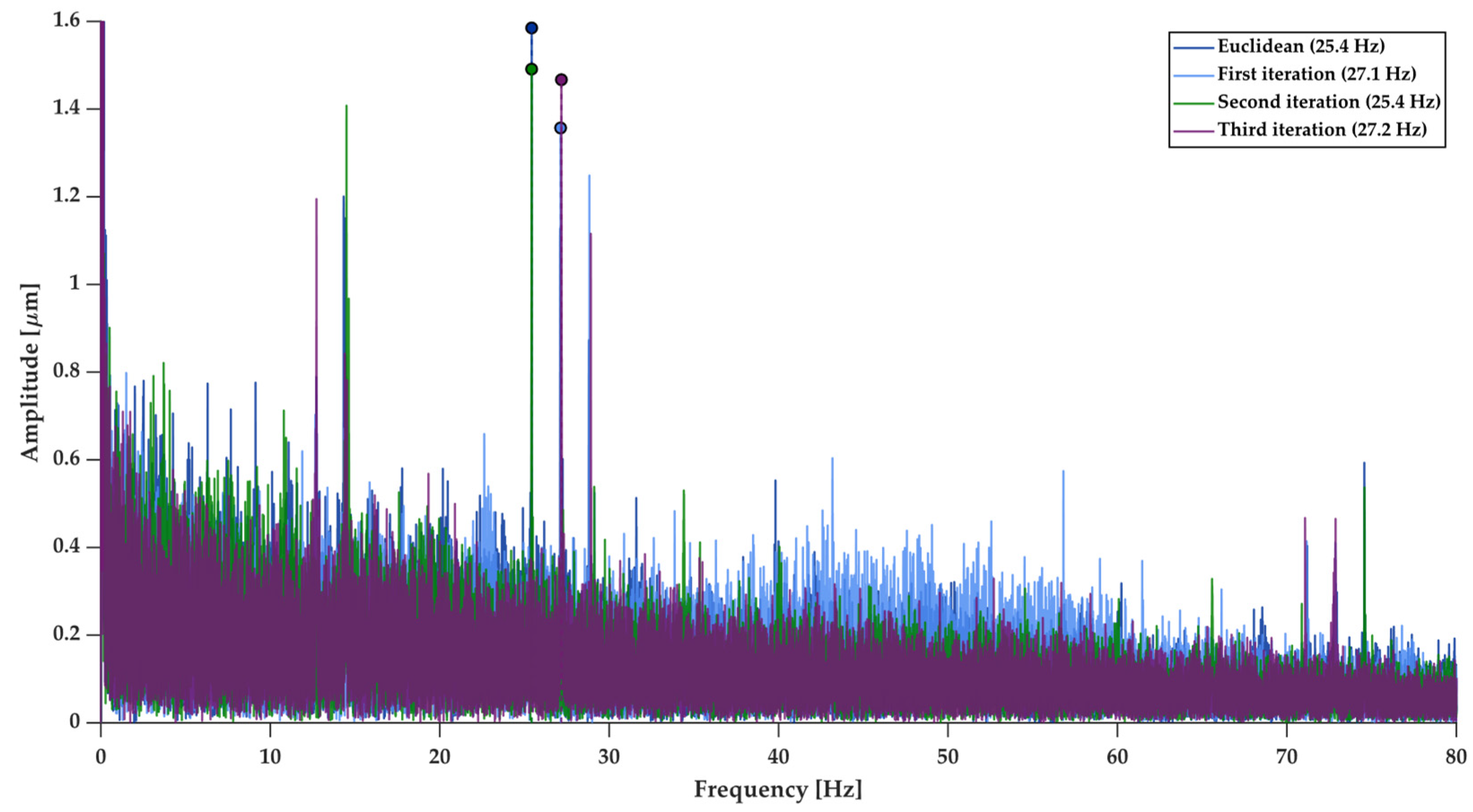
This section presents a comparative analysis of the theoretical and effective stiffness of the studied waveguide beams. The theoretical stiffness was calculated using Equation (1), assuming an elastic modulus of 2 MPa as specified by the manufacturer of the flexible resin. In contrast, the effective stiffness was estimated using Equation (6), based on the experimentally determined natural frequencies extracted from the frequency spectra shown in Figure 4.
Figure 4 illustrates the variations in dynamic behavior associated with the progressive removal of material. The magnitude spectra enabled the identification of the natural frequency of each sample, corresponding to the peak amplitude in each case. The tested beams exhibited resonance frequencies of 24.4 Hz, 27.1 Hz, 25.4 Hz, and 27.2 Hz, respectively. Notably, although the total system mass decreased (from 193 g to 158 g), the natural frequencies did not follow a proportional reduction. In fact, the highest-order fractal beam exhibited the highest recorded frequency. The consistency of the peaks between 1 and 80 Hz confirms that the energy was concentrated in the fundamental vibration mode, justifying the SDOF model, since there were no significant excitations of higher modes.
The selection of the 1–80 Hz bandwidth was constrained by the hardware’s operational limits but proved adequate to capture the transition between operating regimes for all iterations. Furthermore, the spectral area (Equation (11)) is employed as the primary metric for attenuation because it offers a global quantification of energy dissipation. Unlike damping ratios or loss factors, which are sensitive to specific peak identification, the spectral integral captures the total vibratory energy distributed across the complex fractal spectrum. This approach accounts for the cumulative effect of secondary modes and spectral dispersion induced by self-similarity, which are characteristic of fractal architectures and would be partially omitted by traditional modal extraction methods.
The magnitude spectra shown in Figure 4 provides a clear characterization of the dynamic displacement (μm) across the frequency range. As indicated by the colored dots at the peaks, the natural frequencies were identified at the points of maximum spectral magnitude, confirming the transition of the system’s energy into the fundamental vibration mode.
Table 2 summarizes the theoretical and effective stiffness values, along with the natural frequencies identified from the spectra and the corresponding effective masses. It also reports the relative errors between the estimated stiffness values. The table highlights the evolution of mass, natural frequency, stiffness, and relative error across the different beam configurations.
Additionally, it can be observed that the lower-order iterations exhibit a strong agreement between theoretical and experimental results. However, in the third iteration (i = 3), a relative error of 16.16% is obtained, representing the largest discrepancy in the study. This deviation can be attributed to factors associated with both the increased geometric complexity and porosity of the beam, as well as limitations of the manufacturing process. As the fractal order increases, the structure reaches a higher level of porosity and intricacy, making it more sensitive to slight variations in material distribution, which significantly affect the experimental response. Additionally, despite the use of high-resolution SLA printing, the accurate reproduction of the smallest geometric features in the third iteration may introduce imperfections or edge effects not captured by the ideal analytical model, which in turn affect the actual moment of inertia of the beams.
Despite this discrepancy, the overall trend supports the validity of the proposed methodology. The results confirm that the SDOF model provides a reliable approximation of the dynamic response, although uncertainty increases with the geometric complexity of the metamaterial.

3.3. Assessment of Dynamic Stiffness and Operating Regimes

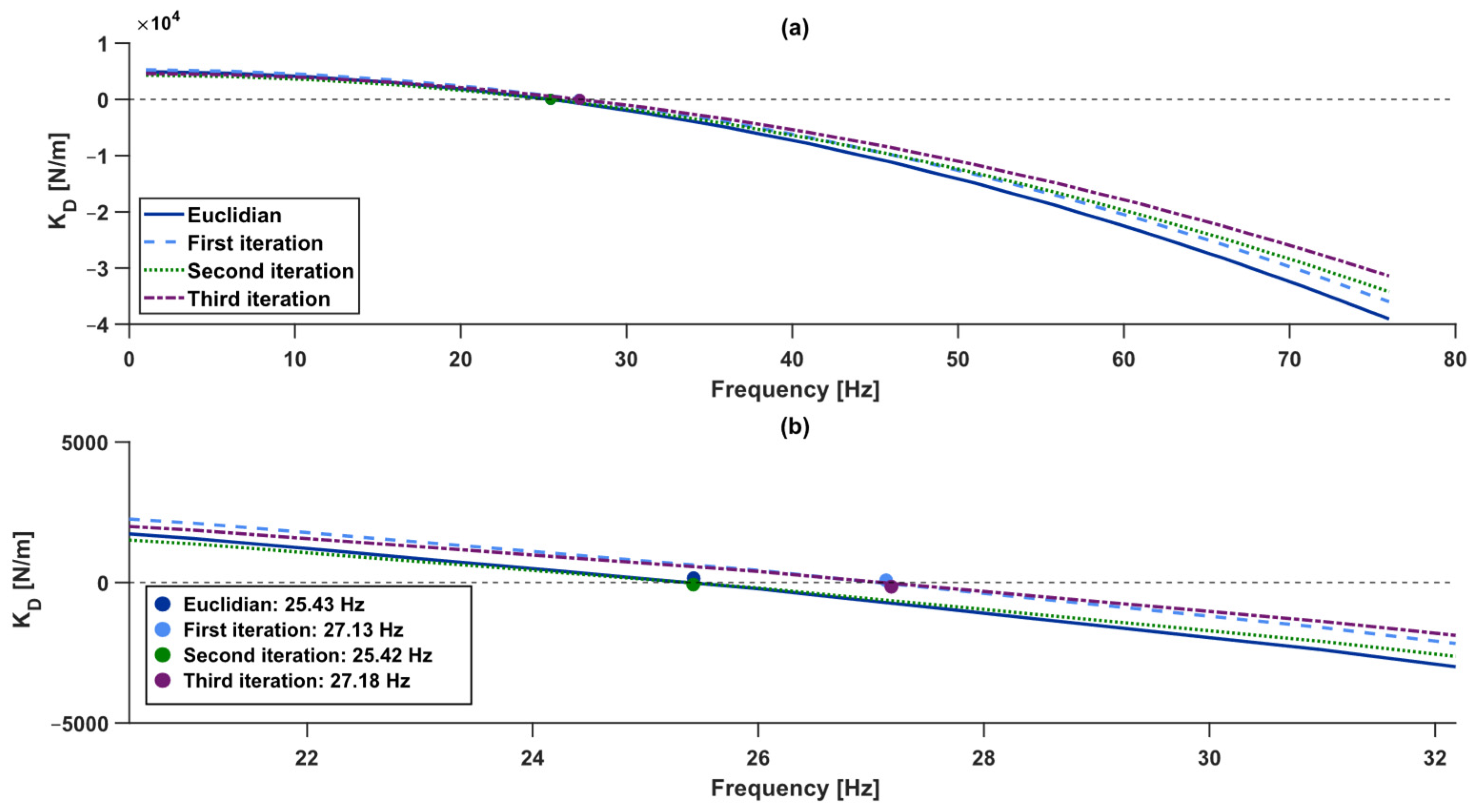
The dynamic stiffness of each beam was evaluated using Equation (9), which enables identification of the transition between stiffness-dominated and inertia-dominated regimes. Calculations have been performed over a frequency range of 1–80 Hz. The results are presented in Figure 5 in two formats: an overall comparison of the four beam configurations and a detailed view focused on the vicinity of their natural frequencies.
In the general graph (Figure 5a), it can be seen that all beams exhibit a decreasing behavior of K D as the excitation frequency increases. At low frequencies, the inertial term is small and the dynamic stiffness remains positive, corresponding to the elastic or stiffness-dominated regime. In this interval, the system response is mainly controlled by the effective stiffness ( K f ) , and the differences between the beams can be explained by their variations in mass and static stiffness.
As the excitation frequency increases, the inertial term grows rapidly until it equals the value of K f . This point corresponds to the natural frequency of each beam, where theoretically dynamic stiffness becomes zero ( K D = 0). The zoomed view in Figure 5b clearly shows this transition, highlighting the zero-crossing of K D . The frequencies at which K D = 0 agree with the natural frequencies identified from the spectra (Figure 4), confirming that the model captures the general experimental behavior.
Additionally, Figure 5b shows that the natural frequencies do not follow a monotonic sequence with increasing fractal iteration; rather, they appear unordered and do not exhibit uniform progression. This non-monotonic evolution of natural frequencies results from the competition between material removal and the redistribution of local stiffness through the Sierpinski multiscale architecture. While the first iteration causes a slight decrease in the stiffness index ( K 1 = 0.96 ), higher-order iterations ( i = 2 , 3 ) leverage self-similarity to optimize the stiffness-to-mass ratio. This creates a waveguiding effect where the porous sub-structures strategically modulate energy transfer, allowing the third iteration to achieve the highest resonance frequency (27.2 Hz) and energy attenuation despite its lower mass. A similar trend is observed in the dynamic stiffness at low frequencies (below resonance). However, as the excitation frequency increases, the dynamic stiffness curves tend to organize according to the iteration sequence (0, 1, 2, and 3). This behavior reflects the combined influence of geometric complexity and mass distribution. The ordering observed at higher frequencies suggests that fractal metamaterials can modulate resonance and dynamic stiffness in a nonlinear manner, leading to a more predictable response as the fractal order increases. Beyond the natural frequency, the dynamic stiffness becomes negative, indicating a transition to an inertia-dominated regime, as clearly shown in Figure 5a, where the curves drop sharply after crossing zero.
The differences observed among the beams can be attributed to their physical parameters: configurations with lower mass and reduced effective stiffness tend to exhibit slightly lower natural frequencies and transition more rapidly into the inertia-dominated regime. Despite these variations, the overall trend remains consistent across all cases, confirming that the SDOF model adequately captures the dynamic behavior within the analyzed frequency range.
Overall, the evaluation of dynamic stiffness and the identification of operating regimes enable a robust characterization of the beams’ vibratory response. This framework provides a reliable basis for comparing configurations and supports a consistent physical interpretation of the experimental results.

3.4. Comparative of Vibration Absorption: Spectral Analysis in Fractal Beams

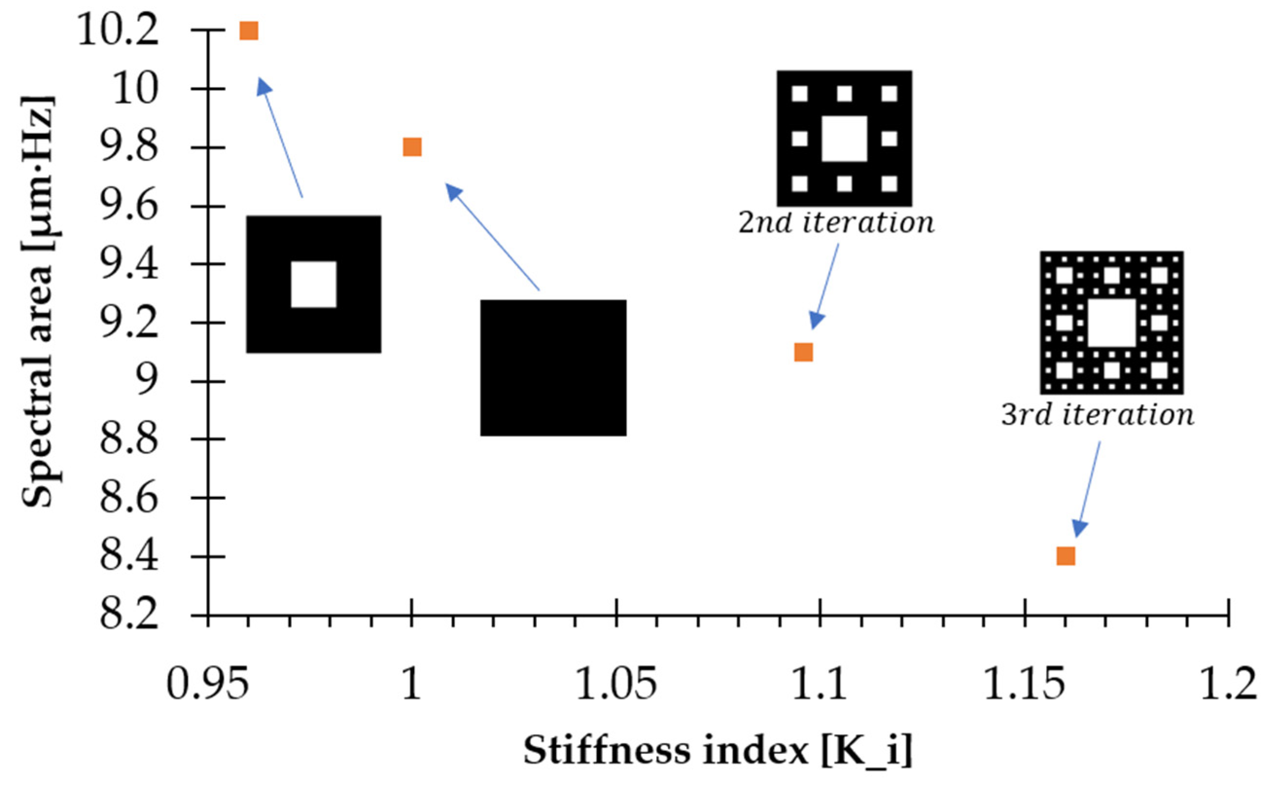
Figure 6 presents the stiffness index calculated from Equation (12) and the spectral area obtained from Equation (11). The FFT-based spectral integrals reveal clear differences in vibration absorption among the four waveguide beams. Beam 3 exhibits the highest absorption, as indicated by the smallest spectral area within the analyzed range, reflecting a lower-amplitude, more distributed response and enhanced energy dissipation. Beam 2 follows, also showing a reduced spectral area relative to the Euclidean beam, though less pronounced than Beam 3. Beam 1 displays a larger area, corresponding to intermediate absorption and a response closer to that of a less complex structure. Interestingly, Beam 0 shows a spectral area slightly smaller than Beam 1, indicating a non-monotonic trend. Overall, the reduction in spectral area with increasing fractal complexity supports the conclusion that higher-order fractal beams achieve more effective vibration attenuation.
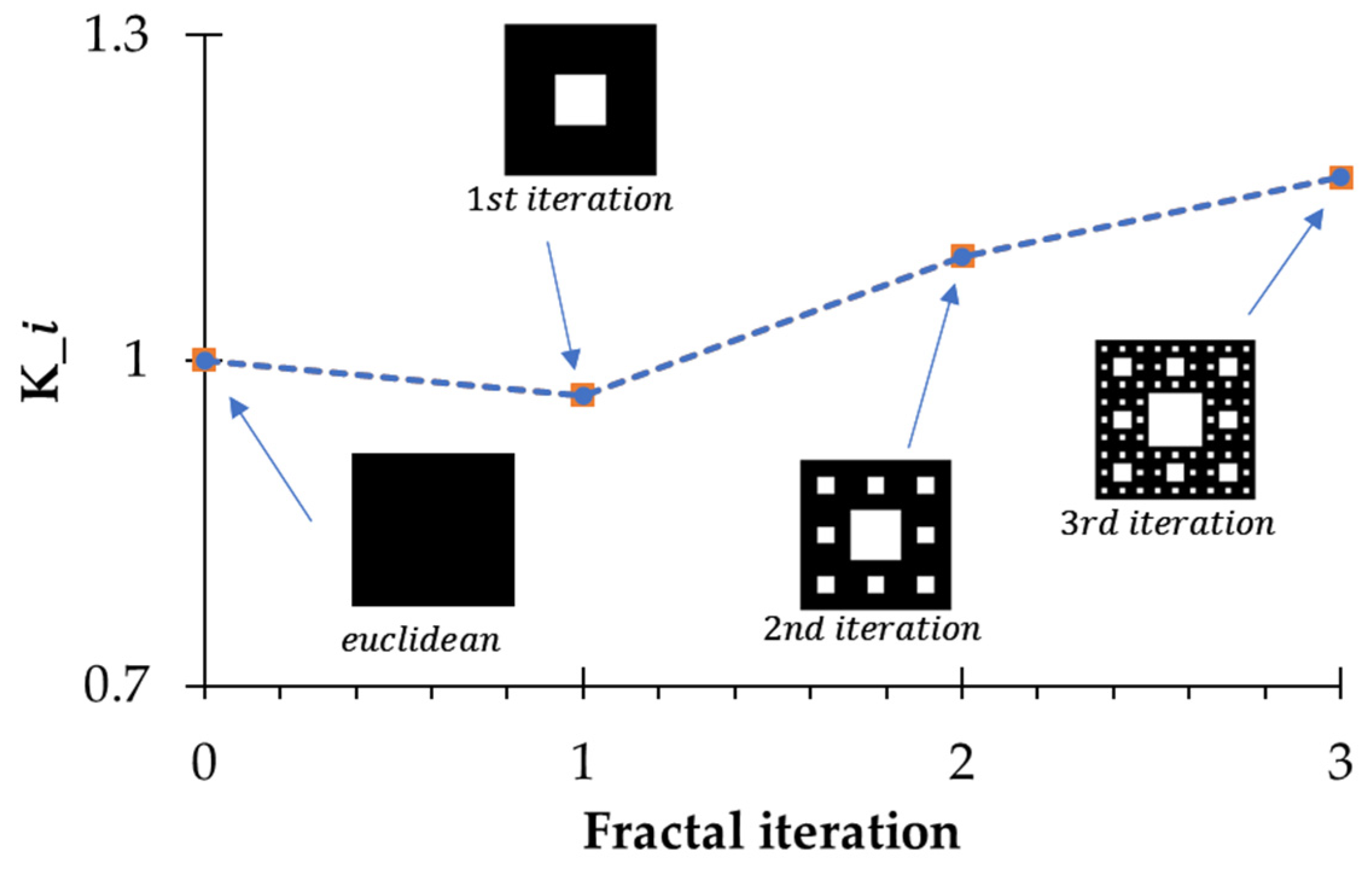
On the other hand, Figure 6 shows that the stiffness index K i evolves systematically with increasing fractal iteration, although the trend is clearly non-linear, as illustrated in Figure 7. For the Euclidean configuration (iteration 0), the reference value is K 0 = 1 . With the introduction of the first fractal iteration, the index decreases slightly to K 1 = 0.96 , indicating reduced vibration absorption relative to the reference geometry. In the second iteration, the index increases to K 2 = 1.09 , marking a transition toward a stiffer response and enhanced vibration attenuation. The third iteration reaches the highest value, K 3 = 1.16 , reflecting the greatest stiffness and the highest absorption capacity among the configurations. This progression indicates that the incorporation of fractal complexity does not produce a monotonic effect; instead, an initial reduction in performance is followed by a steady improvement at higher iterations. The observed behavior suggests that multiscale interactions inherent to fractal geometries modify vibrational energy transfer in a nontrivial manner, giving rise to emergent dynamic properties that become more pronounced as the fractal order increases.

4. Conclusions

This research has successfully demonstrated the technical feasibility of waveguide-type fractal beams based on the Sierpinski set as an advanced solution for modulating and controlling mechanical vibrations. Through detailed characterization of the first three iterations, it was verified that incorporating this geometry enables structures to achieve greater energy absorption capacity compared to conventional Euclidean configurations, while maintaining dynamic integrity despite the progressive removal of mass.
Validation of the dynamic model through a single degree of freedom system proved to be a robust approach for describing the system’s behavior, supported by the high agreement between theoretical and experimental stiffness values. Although a relative error of 16.16% was observed for the third iteration (i = 3), this discrepancy highlights the increased sensitivity of mechanical properties to the geometric complexity and porosity of higher-order fractals. Specifically, at the 1 mm scale of the third iteration, the inherent anisotropy of the layer-by-layer SLA process and slight variations in material distribution become dominant factors that are not captured by idealized assumptions. This result underscores the need to refine analytical models to explicitly account for these manufacturing-related artifacts and edge effects in multiscale metamaterials.
A key finding is the optimization of the stiffness-to-mass ratio achieved through the fractal architecture. The highest-order fractal beam (i = 3) exhibits the highest resonance frequency (27.2 Hz) despite having the lowest effective mass. This behavior indicates that the Sierpinski-based material distribution enhances structural stiffness more efficiently than mass reduction alone would suggest. Consequently, the proposed geometry optimizes the stiffness-to-mass ratio, enabling the beam to function as an effective waveguide that strategically tailors and shifts resonance frequencies through its hierarchical multiscale architecture.
The spectral-area and stiffness-index analyses further show that energy dissipation increases with fractal order, with the third iteration delivering the most efficient performance. Together with the clear identification of operating regimes where dynamic stiffness transitions from positive to negative, these results position fractal metamaterials as promising candidates for lightweight design and adaptive vibration control in advanced engineering applications.
This investigation provides a useful basis for further study of fractal-based metamaterials. The results support their potential for lightweight vibration-control applications and reinforce the value of the proposed experimental framework for characterizing their dynamic response. Possible extensions of this work include refining predictive models and examining more complex loading conditions or three-dimensional configurations. Applications in machinery vibration attenuation may also be considered as a practical line of study.

Author Contributions

Conceptualization, J.A.S.-d.-M. and J.B.P.-F.; methodology, J.A.S.-d.-M.; validation, J.B.P.-F., O.S.-H. and L.I.F.-C.; formal analysis, J.A.S.-d.-M. and V.E.-M.; investigation, J.A.S.-d.-M. and E.C.-U.; resources, L.I.F.-C. and O.S.-H.; data curation, J.A.S.-d.-M.; writing—original draft preparation, J.A.S.-d.-M. and J.B.P.-F.; writing—review and editing, V.E.-M., L.I.F.-C. and J.B.P.-F.; visualization, E.C.-U.; supervision, J.B.P.-F. and L.I.F.-C. All authors have read and agreed to the published version of the manuscript.

Funding

The APC was funded by the Instituto Politécnico Nacional, SEPI-Escuela Superior de Ingeniería Mecánica y Eléctrica, Unidad Zacatenco, via the funding number SIP 20260479. The Secretaría de Ciencias, Humanidades, Tecnología e Innovación (SECIHTI) of the Government of Mexico for the scholarship number 656438.

Data Availability Statement

The original contributions presented in the study are included in the article; further inquiries can be directed to the corresponding authors.

Conflicts of Interest

The authors declare no conflicts of interest.

References

  1. Ormeño, B.L.A. Riesgo Físico y Enfermedades Profesionales En Trabajadores Que Operan Equipos de Vibración En Construcciones Civiles. Rev. San Gregor. 2019, 1, 97–110. [Google Scholar] [CrossRef]
  2. Francisco, L.-R.D. Avances En Aislamiento de Vibración Por Impacto Usando Rigidez No Lineal. Ing. Investig. Tecnol. 2015, 16, 307–316. [Google Scholar] [CrossRef][Green Version]
  3. Gonzalez, R.A.G.; Gonzalez-Rodriguez, A.; Chacon, J.M.; Castillo, F.J. Sistema de Absorción de Vibraciones de Amplio Espectro Basado En Un Nuevo Muelle de Rigidez Variable. Rev. Iberoam. Automática Informática Ind. RIAI 2017, 14, 163–173. [Google Scholar] [CrossRef]
  4. Ibarra, I.J.E.H. Control Pasivo de Vibraciones En Una Estructura Tipo Edificio Utilizando Múltiples Absorbedores Flexibles. Bachelor’s Thesis, Tecnológico Nacional, Pachuca de Soto, Mexico, 2024. [Google Scholar]
  5. Bicerano, J.; Rieke, J.K. Internal Friction in Polymer Systems. J. Acoust. Soc. Am. 1989, 86, S51–S52. [Google Scholar] [CrossRef]
  6. Geethamma, V.G.; Asaletha, R.; Kalarikkal, N.; Thomas, S. Vibration and Sound Damping in Polymers. Resonance 2014, 19, 821–833. [Google Scholar] [CrossRef]
  7. Prieto, S.A. Caracterización Mecánica de Un Material Viscoelástico Mediante Probetas Fabricadas Con Impresión 3D. Bachelor’s Thesis, Universidad de Sevilla, Sevilla, Spain, 2023. [Google Scholar]
  8. Quichimbo, V.M.A. VMED Análisis de Desempeño Estructural En Una Estructura de Hormigón Armado Con Sistemas de Disipación Sísmica. Bachelor’s Thesis, Universidad Politécnica Salesiana, Guayaquil, Ecuador, 2024. [Google Scholar]
  9. Martinez, L.R.A. Diseño y Fabricación de Ruedas a Base de Polímeros Por Medio de Manufactura Aditiva. Bachelor’s Thesis, Universidad Tecnológica Centroamericana, Tegucigalpa, Honduras, 2023. [Google Scholar]
  10. Ion, A.; Frohnhofen, J.; Wall, L.; Kovacs, R.; Alistar, M.; Lindsay, J.; Lopes, P.; Chen, H.-T.; Baudisch, P. Metamaterial Mechanisms. In Proceedings of the 29th Annual Symposium on User Interface Software and Technology; ACM: New York, NY, USA, 2016; pp. 529–539. [Google Scholar]
  11. Jiao, P.; Mueller, J.; Raney, J.R.; Zheng, X.; Alavi, A.H. Mechanical Metamaterials and Beyond. Nat. Commun. 2023, 14, 6004. [Google Scholar] [CrossRef] [PubMed]
  12. Zhang, L.; Liu, H.; Song, B.; Gu, J.; Li, L.; Shi, W.; Li, G.; Zhong, S.; Liu, H.; Wang, X.; et al. Wood-Inspired Metamaterial Catalyst for Robust and High-Throughput Water Purification. Nat. Commun. 2024, 15, 2046. [Google Scholar] [CrossRef] [PubMed]
  13. Yuan, Y.; Ma, S.; Sun, X.; Chen, B.; Luo, Y.; Lin, Z.; Liang, Y. 3D Printed Auxetic Metamaterials with Tunable Mechanical Properties and Morphological Fitting Abilities. Mater. Des. 2024, 244, 113119. [Google Scholar] [CrossRef]
  14. Palomino Ovando, M.A. CGH La Refracción Negativa y Los Metamateriales: Los Nuevos Materiales Para Dispositivos Ópticos. Rev. Interdiscip. Nanociencias Nanotecnología 2008, 1, 21–32. [Google Scholar]
  15. Babaee, S.; Shim, J.; Weaver, J.C.; Chen, E.R.; Patel, N.; Bertoldi, K. 3D Soft Metamaterials with Negative Poisson’s Ratio. Adv. Mater. 2013, 25, 5044–5049. [Google Scholar] [CrossRef] [PubMed]
  16. Maconachie, T.; Leary, M.; Lozanovski, B.; Zhang, X.; Qian, M.; Faruque, O.; Brandt, M. SLM Lattice Structures: Properties, Performance, Applications and Challenges. Mater. Des. 2019, 183, 108137. [Google Scholar] [CrossRef]
  17. Castellanos, L.M.; Lopez, F.; Reyes-Vera, E. Metamateriales: Principales Características y Aplicaciones. Rev. Acad. Colomb. Cienc. Exactas Fis. Nat. 2016, 40, 395. [Google Scholar] [CrossRef]
  18. Hernández, A.; López, F.; Ossa, O. Generación de Doble Banda En Antenas de Microcinta Rectangulares Utilizando Ranuras Separadas En Secuencia de Cantor. Ingeniare. Rev. Chil. Ing. 2020, 28, 204–213. [Google Scholar] [CrossRef]
  19. Zheng, X.; Lee, H.; Weisgraber, T.H.; Shusteff, M.; DeOtte, J.; Duoss, E.B.; Kuntz, J.D.; Biener, M.M.; Ge, Q.; Jackson, J.A.; et al. Ultralight, Ultrastiff Mechanical Metamaterials. Science 2014, 344, 1373–1377. [Google Scholar] [CrossRef] [PubMed]
  20. Rian, I.M. Fractal Geometry in Architectural Education: Three Case Studies. In International Conference on Geometry and Graphics; Springer Nature: Cham, Switzerland, 2024; pp. 370–379. [Google Scholar]
  21. Márquez, E.M.; de Luna, E.R.; De León, D.; Carrión-Viramontes, F.J.; Kryvko, A.; Samayoa, D. Free Vibration Analysis on Fractal Beams. Eur. J. Mech.-A/Solids 2025, 114, 105719. [Google Scholar] [CrossRef]
  22. Polloni, C.J.G. Diseño y Optimización de Vigas de Metamateriales Con Enrejado Quiral Para Supresión de Vibraciones, Utilizando Modelos de Elementos Finitos y Algoritmos Genéticos; Universidad de Chile: Santiago, Chile, 2020. [Google Scholar]
  23. Cartes, G.V.C. Diseño y Evaluación de Vigas Con Remoción Periódica de Material Para La Reducción de Vibraciones; Universidad de Chile: Santiago, Chile, 2023. [Google Scholar]
  24. Zhao, H.; Wu, Q. Application Study of Fractal Theory in Mechanical Transmission. Chin. J. Mech. Eng. 2016, 29, 871–879. [Google Scholar] [CrossRef]
  25. Brake, M.R.W. The Mechanics of Jointed Structures; Springer International Publishing: Cham, Switzerland, 2018; ISBN 978-3-319-56816-4. [Google Scholar]
  26. Kunin, V.; Yang, S.; Cho, Y.; Deymier, P.; Srolovitz, D.J. Static and Dynamic Elastic Properties of Fractal-Cut Materials. Extrem. Mech. Lett. 2016, 6, 103–114. [Google Scholar] [CrossRef]
  27. D’Alessandro, L.; Ardito, R.; Braghin, F.; Corigliano, A. Low Frequency 3D Ultra-Wide Vibration Attenuation via Elastic Metamaterial. Sci. Rep. 2019, 9, 8039. [Google Scholar] [CrossRef] [PubMed]
  28. Ullah, A.M.M.S.; D’Addona, D.M.; Harib, K.H.; Lin, T. Fractals and Additive Manufacturing. Int. J. Autom. Technol. 2016, 10, 222–230. [Google Scholar] [CrossRef]
  29. Viccica, M.; Galati, M.; Calignano, F.; Iuliano, L. Design, Additive Manufacturing, and Characterisation of a Three-Dimensional Cross-Based Fractal Structure for Shock Absorption. Thin-Walled Struct. 2022, 181, 110106. [Google Scholar] [CrossRef]
  30. Hadjileontiadis, L.J.; Douka, E.; Trochidis, A. Fractal Dimension Analysis for Crack Identification in Beam Structures. Mech. Syst. Signal Process. 2005, 19, 659–674. [Google Scholar] [CrossRef]
  31. Mondal, S.; Mukhopadhyay, T.; Scarpa, F.; Naskar, S. Frequency-Band Programmable Piezoelectric Energy Harvesters with Variable Substrate Material, Tip Mass and Fractal Architectures: Experimental and Numerical Investigations. Mech. Based Des. Struct. Mach. 2025, 53, 1603–1634. [Google Scholar] [CrossRef]
  32. Ostoja-Starzewski, M.; Li, J. Fractal materials, beams, and fracture mechanics. Z. Angew. Math. Phys. 2009, 60, 1194–1205. [Google Scholar] [CrossRef]
  33. De La Rosa Silva, S.; Burgos Pintos, A.; Pardo Vicente, M.Á.; Mayuet Ares, P.F.; Rodriguez Parada, L. FRACTAL GEOMETRIES DESIGN For Three-Dimensional Printing: Analysis of Performance and Vibration Response for Product Design. Dyna 2025, 100, 56–62. [Google Scholar] [CrossRef]
  34. Pascual-Francisco, J.B.; Susarrey-Huerta, O.; Farfan-Cabrera, L.I.; Flores-Hernández, R. Creep Properties of a Viscoelastic 3D Printed Sierpinski Carpet-Based Fractal. Fractal Fract. 2023, 7, 568. [Google Scholar] [CrossRef]
  35. Su, H.; Zhu, Z.; Jia, W.; Li, T.; Cheng, Z.; Xiang, H. Analysis of Fractal and Energy Characteristics of Low-Temperature Concrete under an Impact Load. Cold Reg. Sci. Technol. 2025, 235, 104493. [Google Scholar] [CrossRef]
Figure 1. Cross-section and fabrications of the beams: (a) Euclidean, (b) first iteration, (c) second iteration, and (d) third iteration. Units given in mm.
Fractalfract 10 00435 g001
Figure 2. (a) Diagram of a doubly clamped beam and (b) experimental setup.
Fractalfract 10 00435 g002
Figure 3. Single-degree-of-freedom (SDOF) mass–spring system.
Fractalfract 10 00435 g003
Figure 4. Normalized FFT spectra for the Euclidean beam and the first, second, and third iteration beams derived from the dynamic response.
Fractalfract 10 00435 g004
Figure 5. (a) Dynamic stiffness of Euclidean and fractal beams; (b) zoom near zero-crossing, indicating natural frequencies.
Fractalfract 10 00435 g005
Figure 6. Relationship between the stiffness index K i and the spectral area of the fractal waveguide beams.
Fractalfract 10 00435 g006
Figure 7. Stiffness index evolution across Euclidean and fractal iterations.
Fractalfract 10 00435 g007
Table 1. Comparison of mass and inertial properties of the beams studied.
Fractal Iteration ( I )Mass (g)Moment of Inertia (mm4)
0 (Euclidian)12344,200
111143,700
29939,300
38835,100
Table 2. Comparison of theoretical and experimental (effective) stiffness for the beams across different iterations.
Fractal Iteration ( I )Effective Mass (g)Natural Frequency (Hz)Theoretical Stiffness (N/m)Experimental Stiffness (N/m)Relative
Error (%)
019325.45038.764915.222.45
118127.14970.645247.795.58
216925.44472.834327.333.25
315827.23993.144638.1816.16
Disclaimer/Publisher’s Note: The statements, opinions and data contained in all publications are solely those of the individual author(s) and contributor(s) and not of MDPI and/or the editor(s). MDPI and/or the editor(s) disclaim responsibility for any injury to people or property resulting from any ideas, methods, instructions or products referred to in the content.