Article

Online Microfluidic Droplets Characterization Using Microscope Data Intelligent Analysis

by
Oleg O. Kartashov
*,
Sergey V. Chapek
,
Dmitry S. Polyanichenko
,
Grigory I. Belyavsky
,
Alexander A. Alexandrov
,
Maria A. Butakova
and
Alexander V. Soldatov
The Smart Materials Research Institute, Southern Federal University, 178/24 Sladkova, 344090 Rostov-on-Don, Russia
*
Author to whom correspondence should be addressed.
Big Data Cogn. Comput. 2023, 7(1), 7; https://doi.org/10.3390/bdcc7010007
Submission received: 7 December 2022 / Revised: 27 December 2022 / Accepted: 6 January 2023 / Published: 10 January 2023

Abstract

:
Microfluidic devices have opened new opportunities for functional material chemical synthesis in a few applications. The screening of microfluidic synthesis processes is an urgent task of the experimental process in terms of automation and intellectualization. This study proposes a methodology and software for extracting the morphological and dynamic characteristics of generated monodisperse droplets from video data streams obtained from a digital microscope. For this purpose, the paper considers an approach to generating an extended feature space characterizing the process of droplet generation using a microfluidic device based on the creation of synthetic image datasets. YOLOv7 was used as an algorithm for detecting objects in the images. When training this algorithm, the values in the test dataset [email protected] 0.996 were obtained. The algorithms proposed for image processing and analysis implement the basic functionality to extract the morphological and dynamic characteristics of monodisperse droplets in the synthesis process. Laboratory validation and verification of the software demonstrated high results of the identification of key characteristics of the monodisperse droplets generated by the microfluidic device with the average deviation from the real values not exceeding 8%.

1. Introduction

Droplet-based microfluidic systems have proven to be effective in solving the problems of synthesizing new functional materials in several field applications, such as chemistry, biology, and medicine [1,2]. In each individual case, the authors propose a new microfluidic system architecture, a Lab-on-Chip topology, or unique synthesis conditions and parameters to achieve the targets of the synthesized materials [3]. For example, in the study [4], the authors propose a new technology for screening and diagnosing surfactants during the droplet generation, where the platform is controlled and optimized on the genetic algorithm’s support. Microfluidics has gained wide popularity in biomedical engineering [5,6,7]. Some research focuses on exploring the possibilities for microfluidic synthesis based on monodisperse droplets, in general. Thus, work [8] is devoted to the anisotropic metal particles controlled and reproducible synthesis description proposed by the authors, using the example of monodisperse gold particles. In general, the use of droplets as individual carriers of the active substance in the synthesis process provides certain advantages. Using passive fusion methods, positive results were obtained in the cadmium sulfide particles synthesis [9]. In general, microfluidic synthesis made it possible to take a fresh look at existing problems in the field of nanoscale particle synthesis [10]. The use of droplet capillary reactors not only allowed the efficient organization of magnetic iron oxide nanoparticles, but also the rapid change in the morphology of the resulting substance by varying a few experimental parameters [11,12]. The authors’ main efforts are focused on the microfluidic synthesis system’s individual elements creation. In [13,14], a unique microfluidic reactor structure is proposed for the synthesis of silver particles. A very popular topic in this field is the synthesis of microfluidic systems-based synthesis platforms. In [15], the authors propose a platform for the making of drug microparticles, and in [16,17,18] for the synthesis of polymer nanoparticles. In general, droplet synthesis microfluidic technologies provide researchers with a wide and flexible toolkit for manipulating substances’ dimensional and structural characteristics, as well as determining the structural transitions dynamics in materials [19,20,21,22,23].
At the same time, the current task is to automate the continuous screening of monodisperse droplets’ morphological and dynamic parameters that characterize the obtained substances’ properties. The methods and software implementation development of such tools will make it possible to develop effective systems for screening and controlling the parameters and conditions for the synthesis and diagnosis of new materials with target properties in the fewest number of experimental iterations. To solve this problem, researchers used instrumental evaluations of these various methods on the experimental results and methods of machine learning, deep learning, and computer vision. In the paper [24], numerical solution methods for modeling the dynamic characteristics of objects and flows in microchannels with different structures and orientations when considering various influencing factors are proposed. Special architectures of microfluidic systems are used to determine a dynamic characteristic of flow in a microchannel as velocity. For example, in [25], the authors propose a unique optofluidic device, allowing the measurement of fluid flow velocity in a microchannel using a non-contact optical technique. Some solutions in this field focus not only on the extraction of key characteristics of microfluidic synthesis, but also on their prediction with respect to the initial parameters and experimental conditions. For example, in one study [26], the authors propose an effective web-based tool for predicting the morphological parameters of generated droplets based on machine learning models. This approach allows the automated design of microfluidic devices for the required conditions of microfluidic synthesis. The concept of integrated technology and methods for the intelligent analysis of computer vision and droplets to automate and intellectualize the microfluidic synthesis process and build a platform for a digital microfluidic setup is very promising [27,28,29,30,31,32,33,34]. The general intelligent control concept of the microfluidic chemical synthesis process can be the vectors of parameters and predictive experimental conditions in accordance with the material’s target properties or the planning and developing of a winning strategy for dynamically changing the microfluidic system parameters in real time for the monodisperse droplets with targeted properties. The main solutions proposed in this subject area are based on the use of machine learning models or deep reinforcement learning agents trained in a virtual environment that simulates the real behaviour of the experiment process [26,35,36,37,38].

2. Related Work and Problem Statement

The most important point when using microfluidic droplet synthesis is the monodispersed droplets formation principle in the Lab-on-Chip. This process depends on the microchannel’s geometry and the droplet microreactor’s structure [9,37,38]. To form monodisperse water-in-oil macroemulsions, there are several types of microfluidic generator topologies that provide coaxial flows, flow focusing, or T-injection. One of the main parameters that determines the conditions for the emulsion formation is the continuous and dispersed phases’ capillary numbers. In a Lab-on-Chip with flow focusing, depending on the ratio between the capillary numbers, the emulsion formation can occur in a dripping or jet mode. The advantage of using the flow focusing topology is the greater control it has over the droplet generation mode. In addition, due to the droplet introduction into the generator design, which restricts the aperture flow, it is possible to control the formed emulsion size, regardless of its generation frequency. In the proposed study, a Lab-on-Chip was used, the schematic diagram of which is shown in Figure 1.
This microfluidic device was made using 3D printing technology. In this Lab-on-Chip topology, (1) and (2) are the droplet generator, a geometry structure where monodispersed water or oil droplets in an immiscible phase are generated; (3) is the channels where microdroplets are moving in the flow; (4) is the chamber for storing droplets and for flow visual monitoring; and (5) is the outlet port. It contains an inlet for the continuous and dispersed phases and one outlet for collecting the macroemulsion. The device has a reaction serpentine zone, as well as a droplet collector. The channel cross section is 400 µm, and the droplet generation zone narrows to 200 µm; the depth of all channels is 200 µm. The microfluidic device was created using an Asiga UV MAX digital 3D printer (Asiga, Sydney, Australia) with a wavelength of 385 nm and a light intensity of 7.25 mW/cm2. The first layer was chosen to be 25 µm thick and exposed for 20 s. to avoid delamination of the imprint from the platform. The layer thickness was set to 25 µm and each layer was exposed for 1.2 s. To avoid layer separation during the process, the z compensation was set to 300 µm. For better processability of the resin during printing, the printing temperature was set to 45 °C. Immediately after printing, the microfluidic device was sonicated in the IRS for one minute at a frequency of 80 kHz and then placed in a holder for manual washing of the IRS channels. After flushing the channels, the devices were again sonicated and purged with nitrogen gas. Finally, the device was post-cured for 2 min using a UV lamp (Flash type DR-301C, Asiga, Sydney, Australia).
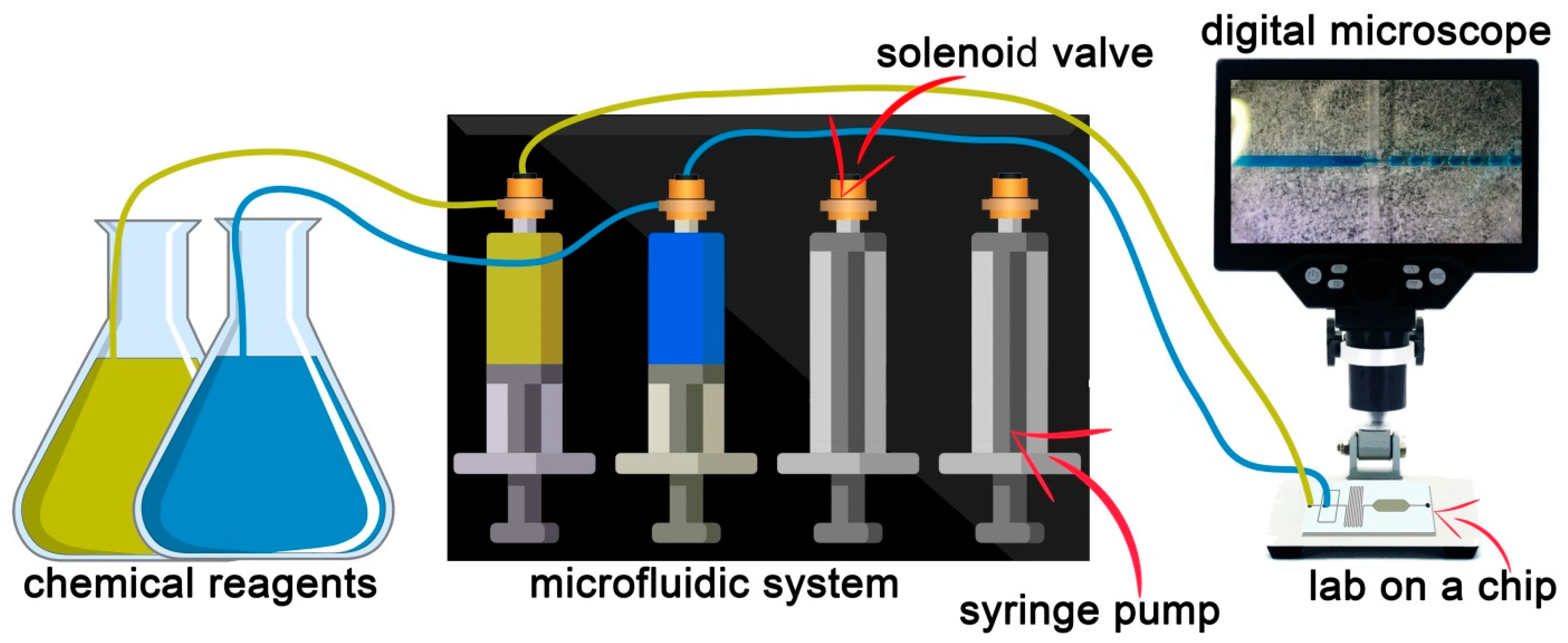
Mineral oil (catalog no. 330779, Sigma-Aldrich, St. Louis, MO, USA) was used as the continuous phase to form a monodisperse microemulsion with the addition of a non-ionic surfactant (surfactant) Span 80 (Sigma-Aldrich, St. Louis, MO, USA). The surfactant stabilized the emulsion and prevented its coalescence by reducing the surface tension and creating a barrier at the interface between the two phases. As a dispersed phase for the formation of droplets, diionized water tinted with methylene blue dye was used at a concentration of 1:10. The liquids were introduced into the microfluidic device using syringe pumps (BYZ-810, Hunan Beyond Medical Technology Co., Ltd, Changsha, China). The flow rate of the dispersed phase was constant and amounted to 200 μL per hour, and the continuous phase rate varied from 200 μL/h to 2000 μr/h. The process of droplet formation was observed and recorded using a digital microscope. The general process of conducting the experiment is shown in Figure 2.
In the proposed study, the analysis objects for extracting the synthesized monodisperse droplets’ morphological and dynamic characteristics will be captured video data streams from a digital microscope. Furthermore, one of the main conditions is online screening in real time to visualize the results with a minimal model inference delay to expand the dynamically changing parameters functionality during the experiment.
The Data Preprocessing paragraph defines the methods used in the study for generating synthetic image data. These image datasets are designed to form an enriched representation of the feature space of possible outcomes of the monodisperse droplet generation process. An automatic procedure is implemented to label the synthetic images, which eliminates the human factor and reduces the time required to prepare the datasets. The paragraph Intelligent Object Detection Models is devoted to the choice of methods for identifying objects in the image. Data on the training and validation of the selected object detection model is presented. The Section 5 describes the proposed methods for analyzing and processing video data streams from the microscope. A modification of the YOLOv7 (You Only Look Once) model logical output system is proposed to extend its functionality within the scope of the list of problems to be solved. The Programs and Tests paragraph presents the main results of the research and shows examples of laboratory tests of the created software. The paragraph Discussion reveals the main limitations of this study and defines the scope and complexity of the problems to be solved and the prospects for further research in this subject area. The final paragraph contains conclusions and experiences gained during the study.

3. Data Processing

Initially, the image processing and analysis classical methods as well as standard computer vision algorithms were considered when solving the monodisperse droplets extracting morphological and dynamic characteristics problems based on microscope video data streams. Intellectualization of the process was required because of the technical means used and the chemical reaction types with high variability, the noise, and distortions present, which greatly hampered the operation in the spatial and frequency images domain and affected the accuracy and detecting monodisperse droplet reliability on video recordings from a microscope. As a result, it was decided to discriminately model the process using the one-stage detector algorithm-trained model.
To ensure the formation of feature space extracted by the model and providing the reliable detection of objects, it is required to expand the initial data sample. Since we are talking not only about the already known reaction control, but also about maintaining functionality when setting up new experiments for the functional material microfluidic synthesis, it is required to ensure a stable pattern formation based on visual data that considers geometric shapes, sizes, and colors variety, including signs occurrence, which is an unlikely event. To form such a unique data set, an infinite number of staged experiments would be required, which would incur enormous resource and time costs, which is an inefficient approach to solving the problem. In addition, even having such an example of an available sample, it would be necessary to carry out its labeling in a qualitative way, which leads to even greater costs.
To quickly solve this problem, it is proposed to create synthetic image datasets that consider such high variability and distortions and noise presence, as in the original. In addition, this approach allows for automatic data labeling, eliminating the human factor and, consequently, qualitatively affects the final precision of the model being trained [39]. The proposed approach to the methods implementation and the software development for generating synthetic image data of the capillary microfluidic synthesis results is to create algorithms that model an unknown data distribution, considering the restrictions imposed on the droplets geometric shape, size, and color, and also to combine these parameters with different arbitrary probabilities. This will go significantly beyond the representative real data sample and provide the droplet stability detection possibility under any, even previously unknown, conditions. The main software tools for the implementation of synthetic image modeling were: Blender 3D graphics environment and its application programming interface; and the functional programming language Python.
The microfluidic synthesis images synthetic datasets generating and labeling took place in several stages. At first, using the application programming interface Blender and using the Python programming language, sphere and ellipsoid templates were created in a virtual environment scene. To do this, at the initial stage, a vertex is created, which is the future sphere lower point. The classical circle formula was then used to define the series of radii of two-dimensional geometric shapes. This happened in two directions. The first step was performed according to the circle and vertex current radii were assigned according to the formula. The second step was to create the next circle over the previous one with a proportional change in radius. These steps are repeated until the vectors for all the circles that model the sphere have been assigned. The more steps we take at each stage, the more polygons the three-dimensional figure surface will end up with resulting in a “smoother” sphere. Then, all the obtained vertexes are connected by edges, considering four neighboring circles belonging to two neighboring circles, with two points each, to form faces. Thus, moving from top to bottom, we create the sphere surface fragments until we run out of free vertex.
The formula for a regular ellipse was used to create a three-dimensional ellipsoid template. The three-dimensional ellipsoid figure software reconstruction general structure corresponds to the procedure for creating a sphere, except for operating with two radius values, and not one as in the first case. In this way, two general templates of a sphere and an ellipsoid were created. They correspond to two formalized microfluidic synthesis droplet geometry cases using a droplet generator. In principle, we separated these two cases to obtain droplets two classes in the future. This was done for objective reasons and will make it possible to calculate the synthesized droplet volume more accurately from its microscopic image.
The next stage was devoted to the materials and modifiers development that allow the automated implementation droplet images variability on synthetic data. Two materials were developed, one of which was a droplet representing the image form, and the second was in the mask nature to implement the generated data automatic labeling function. Each of the materials has its own shader. In the first case, a noise texture with a gloss effect was integrated, which made it possible to implement a blur change by choosing Fresnel coefficients in the range of values from 0 to 1, where a coefficient equal to 1 gives a high level of image blur. In general, it was necessary to cover the contour of a geometric figure, and here a coordinate node was created, connected to a 3D noise texture, combined with a 1D noise texture. Furthermore, by connecting the resulting block with emission, the effect of blurring the contour of the sphere was obtained, which in turn made it possible to adjust the internal color gradient of the synthetic droplet by changing the Fresnel coefficient and transparency. The general shader structure for the first material is shown in Figure 3.
In the second case, to create a mask shader, we needed to represent the generated objects in a uniform white color. For this, Emission and the Principal BSDF were used, where the adjustment took place by changing the mixing ratio through white.
The main droplets generated features in dynamics by a certain transient process of establishing their geometric shape. As well as the geometry features in general, as mentioned earlier, all the synthesis results can be formalized through two ideal three-dimensional figures, but in the future, when intelligently analyzing video data streams from a microscope and detecting drops of two classes, it is necessary to extract the required features for reliable identification and recognition of the control objects with geometry slightly different from ideal.
In general, face smoothing is applied to existing templates. Then, the arbitrary selection function for several templates within one created scene is implemented. This value is regulated by the objects minimum and maximum number and in our case is in the range from eight to twelve pieces, with the subsequent specification of the number relative to the figure final size. In the microfluidic drop synthesis study case of images, it is practically impossible to obtain a situation where one type of geometry replaces another with a high frequency during the next droplet generation, but in general, there can be moments with a change in the geometry type within a series of monodisperse droplets within the experimental parameters during the synthesis. For the algorithm to operate stably on synthetic images, an arbitrary set of droplets of various geometries are implemented. Therefore, after selecting the objects number, the automatic selection and arrangement of the sphere and ellipsoid templates takes place, provided that in the scene from the total droplets number there must be at least two of the figures’ presented types. Then, for each of the templates, the size is randomly chosen in arbitrary units and in the values range from 0.1 to 0.3 blender unit. At the next step, the first type is applied to all objects, where the RGBA randomization procedure is implemented using the Basecolor parameter located in the Principal BSDF module, if A is always equal to 1. Next come the two modifiers (Simple Deform). To ensure the objects’ spatial forms’ variability, the modifiers assignment is dependent and arbitrary. This means that the procedure for choosing the first modifier purpose, whether it will be used or not, and then the second, considering the first one’s parameters formation, is initially implemented. It is necessary to consider the first modifier parameters when designing the second, so that there is no violation of the generated three-dimensional object spatial geometry. The modifiers implement a procedure for determining the deformation type based on stretching or cone. These deformation types were chosen as the most representative for solving the problem and not violating the template figures smoothness. Then, there is an automatic adjustment of the deformation-selectable type parameters, as well as the choice of the axis along which the distortions will be implemented. In our case, three cases are considered, only the X axis, only the Y axis, or the X and Y axes. Then, depending on the deformation type choice and the axis along which the distortion will occur, there is a limited choice of the deformation factor value (multiplier). The deformation axis choice is one of the conditions for assigning the second modifier and forming its parameters set. This implementation feature is associated with the need to modify the figure along the X and Y axes so that the change in geometry occurs evenly on all figure sides and does not require its rotation.
When we have the prepared objects set, we need to place them in the scene according to the formation in one line. This arrangement is typical for monodisperse droplet microfluidic generator channels. To do this, in turn, each next object is placed to the left of the previous one at a distance that is a multiple of 1.5 object widths in two-dimensional coordinates. This process continues until we reach the placement limit of −3.4 blender unit. This indicator was chosen considering the future image at a resolution of 1920 by 1080 pixels. If the placement limit was reached earlier than it was possible to place all the generated objects according to the specified template number, the placement is terminated. This scenario is useful in cases where the figure sizes are arbitrarily selected and the function for choosing the objects’ number in all cases gives the maximum values. A line is created under the distributed objects and stretched to the future image target resolution. The plane is fitted closely; in this case, the scale limit was selected experimentally. Using the graphics processing environment, we prepared in advance a texture that mimics the Lab-on-Chip surface. This texture is superimposed on the created plane to ensure the synthesized graphic data reliability. It was also necessary to adjust the lighting for the scene, which should correspond to the conditions for conducting an instrumental study of the microfluidic chemical synthesis results. For this, the Sun was chosen as a light source with a light propagation corpuscular type, and the source power was set at 50,000 points.
After preparing the scene, the next step was to render synthetic monodisperse droplets microscopic images datasets. This was implemented like a cycle to create several thousand images in jpeg format, the resulting image sample is shown in Figure 4.
Parallel to it, for each such image, its black-and-white mask was generated. To create this image mask, material two was applied to the generated objects and a solid black texture was applied to the plane. The mask image data was rendered in png format with the same resolution and spatial elements arrangement. The resulting image mask sample is shown in Figure 5.
The png format was used because of the alpha channel preservation considerations, i.e., producing images without compression. The image files names in the first and second cases were the same.
In the next stage, an algorithm for automatic pseudodroplets labeling in synthetic data was developed and implemented. For the proposed algorithm, black-and-white synthetic images masks were used. To do this, using the Pillow library, we converted the color space from the RGBA standard to HSV. After color space conversion, pixel-by-pixel image processing took place. The pixels were processed from top to bottom, from left to right. In each pixel data array column, a search was made for a volume greater than 10 in HSV values. After finding the first pixel, the search function was started for the last white pixel in the column. The coordinate addresses of all the first and last pixels with volume > 10 are recorded in a separate data array. After that, a transition to the right occurred and the script repeated until there were only black pixels in the column. This means that the first droplet descriptor is finished. The operation was repeated until the image spatial region ends and the descriptions for all the figures were retrieved. Then, in each array corresponding to one pseudodroplet, the minimum and maximum values of the x and y coordinates were found. As a result, four points characterizing our region of interest were extracted. To correctly interpret the images labeling for the training of the algorithm for detecting and classifying objects, the txt format text file was created. Data about marked objects were written line by line to this file. The data label formation principle is presented in Algorithm 1.
Algorithm 1 Tailoring data labeling for the target model
    INPUT: Top left pixel position (x, y) and bottom right pixel position (x, y) of Bounding Box, image width, and height
OUTPUT: List with YOLO-format parameters (class, x-center, y-center, width, height)
start function
p_1 = [bbox [2][0], bbox [0][1]]
p_2 = [bbox [3][0], bbox [0][1]]
p_4 = [bbox [3][0], bbox [1][1]]
width_p = p_2[0]–p_1[0]
height_p = p_4[1]–p_2[1]
width = width_p/image.width
height = height_p/image.height
x = ((p_2[0] + p_1[0])/2)/image.width
y = ((p_4[1] + p_2[1])/2)/image.height
class = 0
if width_p/height_p > 1.2 then
   class = 1
else
   class = 0
yolo_format = [class, x, y, width, height ]
return yolo_format
end function
All text descriptions retain the child image names. The labeled image sample is shown in Figure 6 and Table 1.
The data given in Table 1 correspond to the class and position of the objects in Figure 6. Class 0 corresponds to the approximated spatial shape of the drop-sphere, and 1 to an ellipsoid. The marking of the objects on the images was performed using Algorithm 1 above.
The original microfluidic drip synthesis video stream captured from a digital microscope is quite noisy. In addition, the real digital microscopes models used in the instrumental study process of the experiment results are quite different. They have different video stream output resolutions, support video recording with different frames per second, and are also subject to various distortions and noise due to technical and optical features. Therefore, it was decided not to filter and process the input stream of video data from the microscope, but to expand the data-used feature space for the training of the model by introducing noise and distortions into the synthetic sets. At the beginning, a randomized choice a is randomized in a synthetic data postprocessing scenario a. Among the scenarios used are: changing the image quality factor in the range from 1 to 5 (multiplying by 10 we get an original image quality percentage); blurring; and introducing noise. Among the main noises used are Gaussian, Spekle, Poisson, Salt, Paper, Salt, and Paper. After post-processing at the output, we get a labeled dataset of the droplet synthetic images, considering the great variability and the problem being solved of specificity.

4. Intelligent Object Detection Models

Intelligent object detection models in this section refer to machine learning models, deep neural network architectures, and complex computer vision algorithms for object detection and classification of images. Reliable object identification by these models requires a training set of labeled data to implement a learning procedure with a teacher. This choice was due to the weak formalization of potentially possible images of monodisperse droplets and the variety of noise introduced by different models of digital optical microscopes. One of the alternative approaches to solve the designated problem could be the development of a mathematical model of generated monodisperse droplets to form feature spaces based on the key characteristics of identification objects. This approach required the implementation of a numerical method of image search, including two stages where the first one selects the applicants, and the next one uses the joint classification method to make the final selection. However, this approach, other things being equal, is more computationally expensive than some trained models of one-stage and two-stage detectors and requires more time to generate analysis results. To solve the monodisperse droplets stable online detection problem based on digital microscope video streams data, several algorithms for one-stage and two-stage detectors, as well as machine learning models and neural networks, were considered. Basically, most of the existing approaches cannot be used in the current study due to the requirements for soft real-time inference generation. Therefore, our attention was focused on the algorithm consideration for one-stage detectors YOLO algorithms which turned out to be more suitable for solving our problems. According to data given in [40,41], the version of the YOLOv7 algorithm is currently the fastest and most accurate means of detecting and classifying objects in images. In addition, the algorithm source code is available in a public repository, so the algorithm functionality extension required in our project is quite convenient for integrating the program code into inference generation modules, as well as extracting data about the Bounding Box. Thus, the algorithm was trained exclusively on synthetic image datasets. The hyperparameters shown in Table 2 were used for training.
Training was performed on an Nvidia RTX 8000 GPU (48 GB DDR6 VRAM) for 300 epochs and took 2.8 h. The training and test set consisted of 3000 synthetic image samples. There was a division into training (2300 images), test (500 images), and validation (200 images) samples. During the training process, the object detection and classification model reached the best value on the [email protected] test set of 0.996. The main training and validation metrics for the YOLOv7 model are shown in Figure 7.
Here, the results group at the top shows the model performance during training, and at the bottom during the validation process. For the qualitative assessment possibility of the trained model in Figure 8, additional metrics and a confusion matrix are given.
After evaluating the results obtained, we can confidently state that the model obtained is highly accurate and stable. The droplet detection sample on a video sequence frame captured from a digital microscope is shown in Figure 9.
When we have achieved confident detection rates and the classification of monodisperse droplets in various forms based on video streams from a digital microscope, it is necessary to implement an image series data analysis to extract the required morphological and dynamic characteristics. These algorithms were interpreted as the YOLO model functionality extension and integrated into the main structure.

5. Monodisperse Droplets Extracting Morphological and Dynamic Characteristics

It is necessary that all the monodisperse droplet characteristics extracted from the video stream be presented in the metric system, and not in conventional units. To do this, it is required to organize the scale factor finding function to bring the considered images’ screen coordinates into the Cartesian system. At the first step, the first frame is extracted from the video sequence and filtered in the frequency domain; for this, the Discrete Fourier Transform is implemented, and low-pass filters are used. Then there is a transition back to the spatial processing area and a brightening of the image by adding a positive constant to the color value for each pixel, in cases where the sum is greater than 255, we force the maximum color value to be written. The resulting image is then processed using the Canny edge detection operator. Since the channel with liquid in the dispersed phase in our case is always located on the right and we know in advance the image spatial resolution, we analyze from right to left, while retreating 20% of the pixels in width. Then we sample nine columns of pixels and in each column, we denote the coordinates of the first and last white pixel. Then we find the difference in coordinates and average it over all nine samples. Since we always know the channel width of a microfluidic chip, using the ratio of the pixels’ average number to the chip channel’s actual value, we find the conditional correspondence of a pixel to the object’s real physical size. A common example of finding the scale factor is shown in Figure 10.
After that, a tensor array is formed that stores the spatial arrangement of the region in the xyxy (min and max) format, the droplet class shape being determined, and the precision percentage being determined. Since there is some false positive detection at a high frame rate and we cannot directly identify specific droplets on the same frame, we filter out records with a detection accuracy value less than the average classification accuracy value within one video frame. Next, the remaining data of the array is sorted in ascending order by the value of the x-coordinate of the Boundary Box. Thus, the droplet numbering on the frame is set, starting from the left most one.
To find the distance between monodisperse droplets in the image, the minimum x value within the nth Bounding Box is taken, where n is the number assigned in the previous step and the maximum x value for n + 1 Bounding Boxes. After that, the difference X max ( n + 1 ) X min ( n ) is found and multiplied by the scale factor to convert to the metric system. This procedure is repeated for each adjacent droplet detection. The inference sample of the distance example between adjacent drops in conventional units is shown in Figure 11.
One of the droplet’s main morphological characteristics for researchers is their volume. To find it, the Bounding Box spatial descriptions in the inference of the used model are also used. Since the Bounding Box boundaries accurately describe the detected object’s location, the droplets two-dimensional projections can be considered inscribed in the Bounding Box. Thus, we are dealing with two formalized figures—a circle and an ellipse. For a circle, we find the Bounding Box center coordinate as the difference between the X and Y coordinates, X max X min and Y max Y min . Then the difference between the maximum value of the x coordinate for the Bounding Box and the x coordinate of the center will be equal to the circle radius and, accordingly, of our sphere, since the possibility of individual deformations along the z axis is not expected, which is associated with the peculiarities of laminar fluid flows in the Lab-on-Chip channels. The existing difference is multiplied by the scale factor and the volume of the sphere V s = 4 3 · π · r 3 is calculated. The ellipsoid in our case is regular and extended along the X axis, so you can find the semi-axes as a = X m a x X m i n and b = c = Y m a x Y c e n t e r _center and find the volume of the figure V e = 4 3 · π · a · b · c .
To find the droplet color in the synthesis process, a 3 × 3 pixel matrix is selected, which coincides with the Bounding Box center determined at the previous step. The resulting values are then averaged over each RGB channel. These morphological characteristics are constantly updated and averaged over a frame series. A frame series is determined by the magnitude of the change in these morphological parameters. If there is a sharp change in one of them, the average values are reset, and a new recalculation begins.
One of the monodisperse droplet’s main dynamic characteristic that determines the synthesized substance behavior is its speed. To find the speed on the frame, two extreme left Bounding Boxes are fixed. For each of the drops, the value of the minimum x coordinate is stored. This coordinate value extraction is repeated for each frame and always with the two left detectable droplets. We also constantly evaluate the minimum x coordinate value for a droplet located at the image space on the left edge. This estimate allows you to track the moment the droplet leaves the frame and, as a result, the detection loss. Then the numbering is reassigned and the minimum coordinate array of the two extreme neighboring Bounding Boxes is overwritten. Thus, we always determine the change in the minimum x coordinates for the second droplet from the left within adjacent video sequence frames. Having made a frame selection, before reassigning the numbering, we will get the total difference between the x coordinate values and the frame number for which this change occurred. We will also need to extract metadata from the digital microscope video file to determine the frame’s number of the real time sequence per second. After that, a series is formed from i = 1 to the frame value obtained, where you can find the sum of the coordinate changes sum in the form i = 1 f p s | x i · c o e f x i 1 · c o e f | . Then, this sum can be divided by the number of frames per second and multiplied by the scale factor to find the speed.

6. Programs and Tests

The main approach scheme of this study is introducing in Figure 12.
Supplementary Materials, including the study code and the necessary descriptions for its use, as well as examples of work, are deposited in the public repository of projects at: https://github.com/codeConcil/droplets_detection (accessed on 7 December 2022) and cloud storage at: https://drive.google.com/drive/folders/1ByIo2A2Y6yNHHRejmqk8EyVaCg_DhWeG?usp=sharing (accessed on 7 December 2022). To check the proposed solution’s accuracy and adequacy, a few staged experiments were carried out on the microfluidic droplet synthesis instrumental study based on digital microscope video streams. For this, parameters were selected, including different colors, speeds, sizes, and geometries of the generated monodisperse droplets. Examples of the results obtained are shown in Figure 13.
The extracted characteristics comparison with the real ones is shown in Table 3. This table shows the results of the evaluation of the proposed software. In order to implement laboratory testing, a series of staged experiments on microfluidic capillary synthesis were performed, with changing experiment parameters during testing. Table 3 shows the evaluations of four staged experiments with different staining, speed, volume, and the position of monodisperse drops. The field “extract data parameters” in the table shows results of the software for the extraction of morphological and dynamic characteristics of monodisperse drops on the basis of video data streams from a digital microscope. The field “real data parameters” shows the initial values of these parameters manually by experts. The item Deviation score shows the percentage of deviation of results of work of the software from the reference values received manually by the expert. In the evaluation process, the averaged values of the required characteristics collected throughout the experimental synthesis were compared.
As can be seen from the Deviation Score values, an accurate tool was obtained to extract the morphological and dynamic characteristics of monodisperse droplets during microfluidic synthesis. This toolkit will allow researchers to quickly screen new functional materials synthesis and diagnostic processes using microfluidic technologies.

7. Discussion

7.1. Limitations of the Study

The main limitations of this study are related to the screening of microfluidic capillary fusion, where a digital microscope is used as an instrumental method of investigation. For this purpose, microfluidic devices whose channel topology ensures the generation of macroemulsion droplets can be used. An important point in the practical use of the software is the proper setting of the field of view for the digital microscope. In this case monodisperse droplets should be necessarily located on the left side in the frame of video sequence and go beyond image borders when moving. The inclusion of additional objects in the frame under consideration can partially disrupt the functionality of the software and reduce the reliability of the determined characteristics of monodisperse droplets. Correct interpretation of parameters in the metric system requires the correct specification of the real size of the substance channel in the dispersed phase. To calculate the velocity of monodisperse droplets in the channel of a microfluidic device, it is necessary to know the metadata of the video stream captured from a digital microscope. A key parameter directly affecting the quality of the velocity determination is the value of frames per second. The proposed software can maintain its functionality when working with different models of digital microscopes, as well as various parameters of video recordings, such as the number of frames per second, bitrate, resolution, and number of colors. To realize the possibility of online screening of microfluidic capillary synthesis results it is necessary to support data streaming on the microscope side. If this functionality is not available, you can use screen capture and broadcast or use the analysis of an already prepared video file.

7.2. The General Points

One of the main problems of using artificial intelligence methods in solving problems of accelerating the synthesis and diagnosis of new functional materials is the shortage of experimental data. This deficit is not in the simple absence of experimental datasets, but in their variety, capable of characterizing all possible variants of synthesis outcomes, including the most unlikely ones. To collect and prepare for artificial intelligence applications sets of real data that can qualitatively characterize the object or process under study in the experiment requires large time and resource costs. In the proposed study, the analysis of microscopic images is proposed as an instrumental study. In the fields of material science, microscopic studies are widely used to evaluate the results of physical and chemical experiments. They include many different techniques such as scanning electron microscopy, transmission electron microscopy, optical microscopy, multiphoton microscopy, X-ray microscopy, and X-ray laser microscopy. The common point is the representation of the result in an image format. Automating the analysis and processing of microscopic images has long been a hot topic in computer vision. When using neural network models, the main task is to form a stable representation of the feature space capable of qualitatively characterizing the target object or process to form a reliable logical conclusion. To solve this problem, this study proposes an approach to the generation of synthetic data of microscopic images of monodisperse droplets. The main task of such generation is the modeling of the distribution of experimental data able to characterize all valid synthesis outcomes. For this purpose, in the process of synthetic data generation the procedures have been proposed that the implement random assignment of key features characterizing the droplets on the images. The creation of separate masks for synthetic images allowed for the automation of the labeling procedure. The concept of this approach can be extended to all fields of the automation and intellectualization of the analysis of microscopic images, allowing one to significantly reduce the resource investment.
The use of one-stage detector algorithms, in particular YOLO models, as models for detecting objects on images is due to several key advantages. Among the main ones are high speed, precision, the reliability of detection, the ability to seamlessly use the trained model on a wide range of hardware computing platforms, and its open-source code, allowing the necessary modifications to solve highly specialized problems. In general, the proposed software can maintain its full functionality when working with a large list of optical digital microscopes and various microfluidic devices. Using the YOLOv7 algorithm as the base node allows the efficient analysis of video data streams with a high acquisition frame rate. This factor allows the extraction of the morphological and dynamic characteristics of monodisperse droplets at a high rate of droplet synthesis. The proposed concept, individual methods, and software for the analysis of microscopic video data streams allows us to solve a number of problems in the accelerated discovery of new functional materials in related areas of experimental research in the physical and chemical industries.

8. Conclusions

The main novelty of the proposed study lies in the complex integration of the algorithm of a one-stage detector and the authors’ algorithms for the analysis and processing of video data streams captured from a digital optical microscope to solve the problem of extracting monodisperse droplets’ morphological and dynamic characteristics in the microfluidic synthesis process. To ensure the stability and reliability of identification of monodisperse droplets on microscopic images, we proposed a methodology for modeling synthetic data, providing the formation of an extended representation of the feature space, and taking into account the high variability of possible scenarios of the course of microfluidic droplet synthesis.
In the proposed study, a few results were obtained. The main ones are the methodology for generating monodisperse droplet synthetic image datasets and the algorithms development that increase the YOLOv7 model functionality in solving screening problems for microfluidic droplet synthesis of functional materials based on video data streams from a digital microscope. The means for generating and automatically labeling synthetic images made it possible to form a stable and variable feature space representation that characterizes the generating monodisperse droplet process under various conditions and the parameters of the experiment without significant resource and time costs. The trained model for detecting and classifying objects in images achieved a high accuracy of [email protected] at the level of 0.99, which allows us to speak about the identifying reliability of all observed objects. The proposed methods for the joint analysis of video streams and the one-stage detector logical inference made it possible to implement the extracting of the synthesized monodisperse droplets’ morphological and dynamic characteristics process at a qualitatively high level.
In the study process, software was prepared to extract morphological and dynamic characteristics of monodisperse droplets during microfluidic synthesis based on video data streams from a digital optical microscope. An approach based on the modification of the logical output module of the one-stage detector algorithm YOLOv7 has proven to be effective in solving this kind of problem. The low latency of the model result and its low weight allowed the use of computing platforms with minimal system requirements. To verify and validate the proposed solution, test measurements were carried out under laboratory conditions. An evaluation of the proposed approach showed that the magnitude of error levels of the morphological and dynamic characteristics measurement is within acceptable limits. In addition, during the work on the study, the use of exclusively synthetic datasets in the training of object detection models showed high efficiency. From this we can conclude that the distribution of measurement data of simple objects with a small number of highly variable morphological parameters can be directly simulated without the need for many real samples. Moreover, if detailed object descriptions are available, they can be simulated in the absence of real images using the simplest software tools. Individual solutions to modify the YOLOv7 model’s logic output module have shown varying levels of accuracy and reliability. Thus, the function of determining the distance between identifiable objects showed the worst performance, even though all droplets were reliably detected and correctly classified. Some features of the proposed software could still be improved, but the approach proposed in this study could well be considered a technological concept with a working software prototype.
The main direction of further study is the development of an intelligent feedback-based microfluidic droplet synthesis control model for solving problems of new functional materials’ accelerated discovery. The droplets’ morphological and dynamic characteristics data in the synthesis course will be used as feedback for the tools for extracting which are presented in this manuscript.

Supplementary Materials

The following supporting information can be downloaded at: https://github.com/codeConcil/droplets_detection and https://drive.google.com/drive/folders/1ByIo2A2Y6yNHHRejmqk8EyVaCg_DhWeG?usp=sharing, accessed on 6 December 2022.

Author Contributions

Conceptualization, O.O.K., M.A.B. and A.V.S.; methodology, G.I.B.; software, O.O.K., A.A.A. and D.S.P.; validation, S.V.C. and O.O.K.; formal analysis, S.V.C. and O.O.K.; investigation, G.I.B.; resources, M.A.B. and A.V.S.; data curation, D.S.P., S.V.C. and A.A.A.; writing—original draft preparation, G.I.B., O.O.K., S.V.C., A.A.A., D.S.P., M.A.B. and A.V.S.; writing—review and editing, O.O.K. and G.I.B.; visualization, D.S.P.; supervision, A.V.S.; project administration, M.A.B.; funding acquisition, A.V.S. All authors have read and agreed to the published version of the manuscript.

Funding

The research was funded by the Strategic Academic Leadership Program of the Southern Federal University (“Priority 2030”). The authors acknowledge the Ministry of Science and Higher Education of the Russian Federation for financial support (Agreement № 075-15-2021-1363).

Data Availability Statement

Not applicable.

Conflicts of Interest

The authors declare no conflict of interest. The founding sponsors had no role in the design of the study; in the collection, analyses, or interpretation of data; in the writing of the manuscript; or in the decision to publish the results.

Abbreviations and Symbols

AbbreviationsDescription
Texture Coordinate Nodeused for the coordinates of textures, typically used as inputs for the Vector input for texture nodes
Noise Texture Nodeevaluates a fractal Perlin noise at the input texture coordinates
Geometry Nodegives geometric information about the current shading point. All vector coordinates are in World Space. For volume shaders, only the position and incoming vector are available
Fresnel Nodecomputes how much light is reflected off a layer, where the rest will be refracted through the layer
Emission Nodeused to add Lambertian emission shader. This can, for example, be used for material and light surface outputs
BSDF Nodebidirectional scattering distribution function
Glossy BSDF Nodeused to add reflection with microfacet distribution, used for materials such as metal or mirrors
Linear Light Nodemixes images by working on the individual and corresponding pixels of the two input images. Called “Mix Color” in the shader, geometry, and texture context
Hue Saturation Value Nodeapplies a color transformation in the HSV Color Model
Mix Shader Nodeused to mix two shaders together. Mixing can be used for material layering, where the Factor input may, for example, be connected to a Blend Weight node
Principled BSDF Nodecombines multiple layers into a single easy to use node. The base layer is a user-controlled mix between diffuse, metal, subsurface scattering, and transmission. On top of that there is a specular layer, sheen layer, and clearcoat layer
Transparent BSDF Nodeused to add transparency without refraction, passing straight through the surface, as if there were no geometry there
Color Ramp Nodeused for mapping values to colors with the use of a gradient
Material Output Nodeused to output surface material information to a surface object
X min ( n ) X position of the leftmost pixel of the current droplet
X max ( n + 1 ) X position of the rightmost pixel of the next droplet
X max X position of the rightmost pixel of the droplet
X min X position of the leftmost pixel of the droplet
Y min Y position of the bottommost pixel of the droplet
Y max Y position of the topmost pixel of the droplet
V s Volume if the droplet is shaped like a sphere
V e Volume if the droplet is ellipsoidal in shape
a the first (huge) semi-axis of the ellipsoid
b the second (middle) semi-axis of the ellipsoid
c the third (minor) semi-axis of the ellipsoid
r Sphere radius
i = 1 f p s sum of x coordinates of pixels to calculate the speed (fps—frames per second in the current stream)
c o e f scale factor for one pixel
x i 1 left X coordinate of the observed drop from the previous frame
x i left X coordinate of the observed drop from the current frame

References

  1. Sohrabi, S.; Kassir, N.; Moraveji, M.K. Droplet microfluidics: Fundamentals and its advanced applications. RSC Adv. 2020, 10, 27560–27574. [Google Scholar] [CrossRef] [PubMed]
  2. Kulkarni, M.B.; Goel, S.G. Microfluidic devices for synthesizing nanomaterials—A review. Nano Express 2020, 1, 032004. [Google Scholar] [CrossRef]
  3. Xie, X.; Wang, Y.; Siu, S.-Y.; Chan, C.-W.; Zhu, Y.; Zhang, X.; Ge, J.; Ren, K. Microfluidic synthesis as a new route to produce novel functional materials. Biomicrofluidics 2022, 16, 041301. [Google Scholar] [CrossRef]
  4. Bawazer, L.A.; McNally, C.S.; Empson, C.J.; Marchant, W.J.; Comyn, T.P.; Niu, X.; Cho, S.; McPherson, M.J.; Binks, B.P.; Demello, A.; et al. Combinatorial microfluidic droplet engineering for biomimetic material synthesis. Sci. Adv. 2016, 2, e1600567. [Google Scholar] [CrossRef] [Green Version]
  5. Hao, N.; Nie, Y.; Zhang, J.X.J. Microfluidic synthesis of functional inorganic micro-/nanoparticles and applications in biomedical engineering. Int. Mater. Rev. 2018, 63, 461–487. [Google Scholar] [CrossRef]
  6. Zhao, X.; Bian, F.; Sun, L.; Cai, L.; Li, L.; Zhao, Y. Microfluidic Generation of Nanomaterials for Biomedical Applications. Small 2020, 16, e1901943. [Google Scholar] [CrossRef] [PubMed]
  7. Ma, J.; Wang, Y.; Liu, J. Biomaterials Meet Microfluidics: From Synthesis Technologies to Biological Applications. Micromachines 2017, 8, 255. [Google Scholar] [CrossRef] [Green Version]
  8. Abalde-Cela, S.; Taladriz-Blanco, P.; De Oliveira, M.G.; Abell, C. Droplet microfluidics for the highly controlled synthesis of branched gold nanoparticles. Sci. Rep. 2018, 8, 2440. [Google Scholar] [CrossRef] [Green Version]
  9. Hung, L.-H.; Choi, K.M.; Tseng, W.-Y.; Tan, Y.-C.; Shea, K.J.; Lee, A.P. Alternating droplet generation and controlled dynamic droplet fusion in microfluidic device for CdS nanoparticle synthesis. Lab Chip 2006, 6, 174–178. [Google Scholar] [CrossRef]
  10. Wojnicki, M.; Luty-Błocho, M.; Hessel, V.; Csapó, E.; Ungor, D.; Fitzner, K. Micro Droplet Formation towards Continuous Nanoparticles Synthesis. Micromachines 2018, 9, 248. [Google Scholar] [CrossRef]
  11. Ahrberg, C.D.; Choi, J.W.; Chung, B.G. Droplet-based synthesis of homogeneous magnetic iron oxide nanoparticles. Beilstein J. Nanotechnol. 2018, 9, 2413–2420. [Google Scholar] [CrossRef]
  12. James, M.; Revia, R.A.; Stephen, Z.; Zhang, M. Microfluidic Synthesis of Iron Oxide Nanoparticles. Nanomaterials 2020, 10, 2113. [Google Scholar] [CrossRef] [PubMed]
  13. Kwak, C.H.; Kang, S.-M.; Jung, E.; Haldorai, Y.; Han, Y.-K.; Kim, W.-S.; Yu, T.; Huh, Y.S. Customized microfluidic reactor based on droplet formation for the synthesis of monodispersed silver nanoparticles. J. Ind. Eng. Chem. 2018, 63, 405–410. [Google Scholar] [CrossRef]
  14. Liu, G.; Ma, X.; Sun, X.; Jia, Y.; Wang, T. Controllable Synthesis of Silver Nanoparticles Using Three-Phase Flow Pulsating Mixing Microfluidic Chip. Adv. Mater. Sci. Eng. 2018, 2018, 1–14. [Google Scholar] [CrossRef] [Green Version]
  15. Yeap, E.W.Q.; Ng, D.Z.L.; Lai, D.; Ertl, D.J.; Sharpe, S.A.; Khan, S.A. Continuous Flow Droplet-Based Crystallization Platform for Producing Spherical Drug Microparticles. Org. Process. Res. Dev. 2019, 23, 93–101. [Google Scholar] [CrossRef]
  16. Karnik, R.; Gu, F.; Basto, P.; Cannizzaro, C.; Dean, L.; Kyei-Manu, W.; Langer, R.; Farokhzad, O.C. Microfluidic Platform for Controlled Synthesis of Polymeric Nanoparticles. Nano Lett. 2008, 8, 2906–2912. [Google Scholar] [CrossRef] [PubMed]
  17. Park, J.I.; Saffari, A.; Kumar, S.; Günther, A.; Kumacheva, E. Microfluidic Synthesis of Polymer and Inorganic Particulate Materials. Annu. Rev. Mater. Res. 2010, 40, 415–443. [Google Scholar] [CrossRef]
  18. Puigmartí-Luis, J.; Rubio-Martínez, M.; Hartfelder, U.; Imaz, I.; Maspoch, D.; Dittrich, P.S. Coordination Polymer Nanofibers Generated by Microfluidic Synthesis. J. Am. Chem. Soc. 2011, 133, 4216–4219. [Google Scholar] [CrossRef]
  19. Pilkington, C.P.; Seddon, J.M.; Elani, Y. Microfluidic technologies for the synthesis and manipulation of biomimetic membranous nano-assemblies. Phys. Chem. Chem. Phys. 2021, 23, 3693–3706. [Google Scholar] [CrossRef]
  20. Zhang, L.; Niu, G.; Lu, N.; Wang, J.; Tong, L.; Wang, L.; Kim, M.J.; Xia, Y. Continuous and Scalable Production of Well-Controlled Noble-Metal Nanocrystals in Milliliter-Sized Droplet Reactors. Nano Lett. 2014, 14, 6626–6631. [Google Scholar] [CrossRef]
  21. Baruah, A.; Singh, A.; Sheoran, V.; Prakash, B.; Ganguli, A.K. Droplet-microfluidics for the controlled synthesis and efficient photocatalysis of TiO2 nanoparticles. Mater. Res. Express 2018, 5, 075019. [Google Scholar] [CrossRef]
  22. Yaghmur, A.; Hamad, I. Microfluidic Nanomaterial Synthesis and In Situ SAXS, WAXS, or SANS Characterization: Manipulation of Size Characteristics and Online Elucidation of Dynamic Structural Transitions. Molecules 2022, 27, 4602. [Google Scholar] [CrossRef] [PubMed]
  23. Günther, A.; Jensen, K.F. Multiphase microfluidics: From flow characteristics to chemical and materials synthesis. Lab Chip 2006, 6, 1487–1503. [Google Scholar] [CrossRef]
  24. Ali, N.; Asghar, Z.; Sajid, M.; Bég, O.A. Biological interactions between Carreau fluid and microswimmers in a complex wavy canal with MHD effects. J. Braz. Soc. Mech. Sci. Eng. 2019, 41, 446. [Google Scholar] [CrossRef]
  25. Lucchetta, D.E.; Vita, F.; Francescangeli, D.; Simoni, F.; Francescangeli, O. Optical measurement of flow rate in a microfluidic channel. Microfluid. Nanofluidics 2016, 20, 1–5. [Google Scholar] [CrossRef]
  26. Lashkaripour, A.; Rodriguez, C.; Mehdipour, N.; Mardian, R.; McIntyre, D.; Ortiz, L.; Campbell, J.; Densmore, D. Machine learning enables design automation of microfluidic flow-focusing droplet generation. Nat. Commun. 2021, 12, 25. [Google Scholar] [CrossRef] [PubMed]
  27. Rizkin, B.A.; Popovich, K.; Hartman, R.L. Artificial Neural Network control of thermoelectrically-cooled microfluidics using computer vision based on IR thermography. Comput. Chem. Eng. 2019, 121, 584–593. [Google Scholar] [CrossRef]
  28. Durve, M.; Tiribocchi, A.; Bonaccorso, F.; Montessori, A.; Lauricella, M.; Bogdan, M.; Guzowski, J.; Succi, S. DropTrack—Automatic droplet tracking with YOLOv5 and DeepSORT for microfluidic applications. Phys. Fluids 2022, 34, 082003. [Google Scholar] [CrossRef]
  29. Zantow, M.; Dendere, R.; Douglas, T.S. Image-Based Analysis of Droplets in Microfluidics. In Proceedings of the 2013 35th Annual International Conference of the IEEE Engineering in Medicine and Biology Society (EMBC), Osaka, Japan, 3–7 July 2013; pp. 1776–1779. [Google Scholar]
  30. Shin, Y.-J.; Lee, J.-B. Machine vision for digital microfluidics. Rev. Sci. Instrum. 2010, 81, 014302. [Google Scholar] [CrossRef]
  31. Luo, Z.; Huang, B.; Xu, J.; Wang, L.; Huang, Z.; Cao, L.; Liu, S. Machine vision-based driving and feedback scheme for digital microfluidics system. Open Chem. 2021, 19, 665–677. [Google Scholar] [CrossRef]
  32. Rutkowski, G.P.; Azizov, I.; Unmann, E.; Dudek, M.; Grimes, B.A. Microfluidic droplet detection via region-based and single-pass convolutional neural networks with comparison to conventional image analysis methodologies. Mach. Learn. Appl. 2022, 7, 100222. [Google Scholar] [CrossRef]
  33. Esmaeel, A.M.; ElMelegy, T.T.H.; Abdelgawad, M. Multi-purpose machine vision platform for different microfluidics applications. Biomed. Microdevices 2019, 21, 68. [Google Scholar] [CrossRef] [PubMed]
  34. Mudugamuwa, A.; Hettiarachchi, S.; Melroy, G.; Dodampegama, S.; Konara, M.; Roshan, U.; Amarasinghe, R.; Jayathilaka, D.; Wang, P. Vision-Based Performance Analysis of an Active Microfluidic Droplet Generation System Using Droplet Images. Sensors 2022, 22, 6900. [Google Scholar] [CrossRef] [PubMed]
  35. Chen, X.; Lv, H. Intelligent control of nanoparticle synthesis on microfluidic chips with machine learning. NPG Asia Mater. 2022, 14, 69. [Google Scholar] [CrossRef]
  36. McIntyre, D.; Lashkaripour, A.; Fordyce, P.; Densmore, D. Machine learning for microfluidic design and control. Lab Chip 2022, 22, 2925–2937. [Google Scholar] [CrossRef]
  37. Saqib, M.; Şahinoğlu, O.B.; Erdem, E.Y. Alternating Droplet Formation by using Tapered Channel Geometry. Sci. Rep. 2018, 8, 1606. [Google Scholar] [CrossRef] [Green Version]
  38. Zhu, P.; Wang, L. Passive and active droplet generation with microfluidics: A review. Lab Chip 2017, 17, 34–75. [Google Scholar] [CrossRef]
  39. Polyanichenko, D.S.; Chernov, A.V.; Kartashov, O.O.; Alexandrov, A.A.; Butova, V.V.; Butakova, M.A. Intelligent Detection of the Nanomaterials Spatial Structure with Synthetic Electron Microscopy Images. In Proceedings of the 2022 XXV International Conference on Soft Computing and Measurements (SCM), Saint Petersburg, Russian, 25–27 May 2022; pp. 254–258. [Google Scholar]
  40. Wang, C.-Y.; Bochkovskiy, A.; Liao, H.-Y.M. YOLOv7: Trainable Bag-of-Freebies Sets New State-of-the-Art for Real-Time Object Detectors. arXiv 2022, arXiv:2207.02696. [Google Scholar]
  41. Yang, F.; Zhang, X.; Liu, B. Video Object Tracking Based on YOLOv7 and DeepSORT. arXiv 2022, arXiv:2207.12202. [Google Scholar]
Figure 1. The microfluidic device schematic diagram with a Droplet generator (1) and (2)—Channels for supplying liquid substances (3)—Reaction zone; (4)—Droplet collector; (5)—emulsion collection.
Bdcc 07 00007 g001
Figure 2. The instrumental check common scheme based on the chemical synthesis results.
Bdcc 07 00007 g002
Figure 3. The monodisperse droplet material shader.
Bdcc 07 00007 g003
Figure 4. The image generated sample at the render stage.
Bdcc 07 00007 g004
Figure 5. The image mask generated sample at the render stage.
Bdcc 07 00007 g005
Figure 6. The labeled synthetic image sample.
Bdcc 07 00007 g006
Figure 7. The YOLOv7 model training and validation main metrics.
Bdcc 07 00007 g007
Figure 8. The trained model quality metrics. (a) Confusion matrix; (b) Dependency Recall-Confidence; (c) Dependency F1-Confidence; (d) Dependency Precision-Confidence; (e) Dependency Precision-Recall.
Bdcc 07 00007 g008
Figure 9. The monodisperse droplet detection sample on real data from a digital microscope.
Bdcc 07 00007 g009
Figure 10. The image edges to find the scale factor.
Bdcc 07 00007 g010
Figure 11. Determining the distance between adjacent monodisperse droplet on a digital microscope video sequence frame.
Bdcc 07 00007 g011
Figure 12. The main steps of the proposed methods.
Bdcc 07 00007 g012
Figure 13. The proposed software toolkit operation for extracting the monodisperse droplets morphological and dynamic characteristics based on digital microscope video data streams in microfluidic synthesis.
Bdcc 07 00007 g013
Table 1. The sample of synthetic image label storage format.
Class MarkupX-CenterY-CenterWidthHeight
10.05850.49860.03590.0416
00.10070.50.02960.05
10.14600.49860.04210.0472
10.18750.49860.03120.0305
00.23280.49860.03750.0638
00.27260.49860.01710.0305
10.31010.49860.04210.0472
10.35620.49860.03430.0472
00.39290.49860.02030.0361
00.42810.50.02810.05
00.45780.49860.01560.025
Table 2. The YOLOv7 training hyperparameters.
Parameter NameSelected Value
1Momentum0.937
2weight_decay0.0005
3warmup_epochs3.0
4warmup_momentum0.8
5warmup_bias_lr0.1
6Box0.05
7Cls0.3
8cls_pw1.0
9Obj0.7
10obj_pw1.0
11iou_t0.2
12anchor_t4.0
13fl_gamma0.0
14hsv_h0.015
15hsv_s0.7
16hsv_v0.4
17Degrees0.0
18Translate0.2
19Scale0.5
20Shear0.0
21Perspective0.0
22Flipud0.0
23Fliplr0.5
24Mosaic1.0
25Mixup0.0
26copy_paste0.0
27paste_in0.0
28loss_ota1
Table 3. The results evaluation.
SpeedVolumeColorDistance
Experiment 1
(extract data parameters)
0.46 mm/s0.20 mm32 44 720.28 mm
Experiment 1
(real data parameters)
0.5 mm/s0.20 mm32 45 810.30 mm
Deviation score 18%0%within color7%
Experiment 2
(extract data parameters)
2.00 mm/s0.05 mm37 70 940.47 mm
Experiment 2
(real data parameters)
2.00 mm/s0.05 mm35 89 960.50 mm
Deviation score 20%0%within color6%
Experiment 3
(extract data parameters)
0.32 mm/s0.20 mm3201 43 00.38 mm
Experiment 3
(real data parameters)
0.250.20 mm3202 47 20.30 mm
Deviation score 328%0%within color27%
Experiment 4
(extract data parameters)
0.83 mm/s0.03 mm3191 89 571.35 mm
Experiment 4
(real data parameters)
0.80 mm/s0.03 mm3193 89 520.5 mm
Deviation score 44%0%within color170%
Disclaimer/Publisher’s Note: The statements, opinions and data contained in all publications are solely those of the individual author(s) and contributor(s) and not of MDPI and/or the editor(s). MDPI and/or the editor(s) disclaim responsibility for any injury to people or property resulting from any ideas, methods, instructions or products referred to in the content.

