1. Introduction
Due to the climate impact of electrical power generation from fossil sources as well as aircraft propulsion systems driven by regular jet engine fuels, there are two main pathways for the future development of those systems. On the one hand, further steps in the understanding and prediction of the aerodynamic, aeroelastic, and aeroacoustic characteristics of turbomachinery are needed. On the other hand, there is a strong request to investigate and understand the impact of new fuels and alternative combustion processes for jet engines. These requirements mentioned above have in common the strong request for new design tool validation on an experimental basis.
To meet these requirements with regard to academic and industrial research, the Leibniz University of Hannover has decided to build up a new turbomachinery and combustion technology test facility at the new campus for mechanical engineering [
1] at Garbsen.
The constantly increasing level of electrical power generated by wind turbines and solar systems has led to a massive change in the electrical power grid in Europe, especially in Germany [
2]. Although electrical energy from wind can temporarily cover large parts of the required power, conventional power plants are needed to ensure that enough power is available at all times at every place within the grid, especially during the winter term [
3]. Currently, the required power from conventional sources from time to time reaches nearly 100% of the overall produced power, although the installed net power of wind turbines can theoretically cover almost 50% of the required power. As a result, especially during the summer, a massive and quick change between electrical power produced by fluctuating renewable energies and conventional power plants has to happen. These high load gradients of up to 15 GW/h have already been expected in the past [
2].
In parallel to the increasing amount of fluctuating power generation from wind and solar sources, the volume of re-dispatched energy, which means unplanned changes in grid operation, has increased by a factor of 43 between 2010 and 2020. It can be expected that this effect is spreading from the German power grid to the European grid, as power generation all over Europe is still subject to change with regard to renewable energies [
4].
For future turbomachines for power generation, the market development described above means a strong request for highly flexible use with high numbers of start–stop cycles and load variations, as well as probably new designs like hydrogen-driven turbines or new thermodynamic-cycle processes, i.e., using supercritical CO2 cycles based on geothermal supply.
Current and future jet engine development will have to cope with strong market regulations by governments worldwide. These regulations focus on the strong reduction in the climate impact of worldwide travel as well as on local noise reduction, especially in the direct vicinity of airports and adjacent glide slopes. Two foci of future development efforts will be on massive aerodynamic changes in aircraft engine components driven by the mechanical evolution of concepts, i.e., geared turbofan designs, as well as on new concepts and an extended understanding of noise effects within the engine. Although direct noise emissions from jet engines have been drastically reduced over the last decades, there is still a significant lack of understanding with regard to noise generation and noise transport within multirow turbomachines [
5].
In conclusion, it can be stated that efficiency as a first-order design criterion is replaced by a reduction in emissions and capability for flexible operation while using new combustion technologies and aerodynamic designs.
2. New Experimental Test Facilities for Energy Conversion Processes
The Leibniz Universität Hannover has decided to establish the new research alliance “Dynamics of Energy Conversion.” The following section will provide a detailed insight into the new air supply system with regard to turbomachinery testing and will focus on the development of high-performance settling chambers required for new test rigs.
2.1. Aerodynamic Operating Parameters for the New Test Facilities
To validate computational models, resources such as a test facility are required. Technical boundary conditions, as well as the required budget, are always critical issues in research. For fundamental research as well as near-product design testing, the aerodynamic, aeroacoustic, and aeroelastic scaling methods are based on Mach number Ma, Reynolds number Re, and the reduced frequency k.
Furthermore, the geometrical and power-related scaling of turbomachines is also limited by geometric and mechanical constraints, i.e., increasing rotational speed. The new test facilities at Leibniz University have been designed to operate with up to 25 kg/s at a pressure range between 25 kPa and 800 kPa absolute pressure. The maximum temperature at the test rig’s inlet is 200 °C. Furthermore, the new test facility is capable of operating a large variety of test rigs in open-loop or closed-loop modes. During closed-loop operation, the fluid within the piping system is used in a closed circuit, providing higher or lower (below atmospheric) pressure levels as well as less interaction with environmental influences.
2.2. Test Facility Layout
Figure 1 shows a schematic view of the test facility’s overall layout. The facility was designed and built by AERZEN and was officially taken into operation in 2021. It can be seen that the core components of the facility consist of two large root-type blowers and two large screw compressors that are connected to the test rigs by a complex piping system [
6]. While overall temperature and pressure levels are adjusted by several heat exchangers and bypass-air systems, the high-quality local flow characteristics upstream of test rigs have to be ensured as well. The focus of this paper is on the experimental validation of the operational behavior of settling chambers that are installed upstream of the test rigs in order to provide high-quality inflow.
3. Settling Chamber Design
For the design of aerodynamic settling chambers for test rigs and other applications, very little open literature is available to the public. Most of the settling chambers of existing test facilities were designed between 1950 and 1980. Modern CFD methods and a large number of experimental investigations over the last decades have significantly reduced the number of operating hours for experimental research. Authors of former studies [
7,
8] regarding the design of settling chambers and wind tunnels mostly rely on basic fluid mechanic equations and procedures, and there is even less literature with regard to the use of CFD for calculating the flow through such structures. During the design phase of the settling chamber, several restrictions had to be taken into account. These restrictions were mainly set by the available space for installation and the wide operating range, such as
Maximum overall length: 5 m
Maximum diameter: 2.5 m
Inlet and outlet pipe diameter: 0.7 m
Operating pressure: up to 800 kPa
Operating temperature: up to 200 °C
Extremely wide range of through-flow velocities
Homogeneity of flow characteristics at the outlet is suited for state-of-the-art CFD-tool validation for the connected test rigs
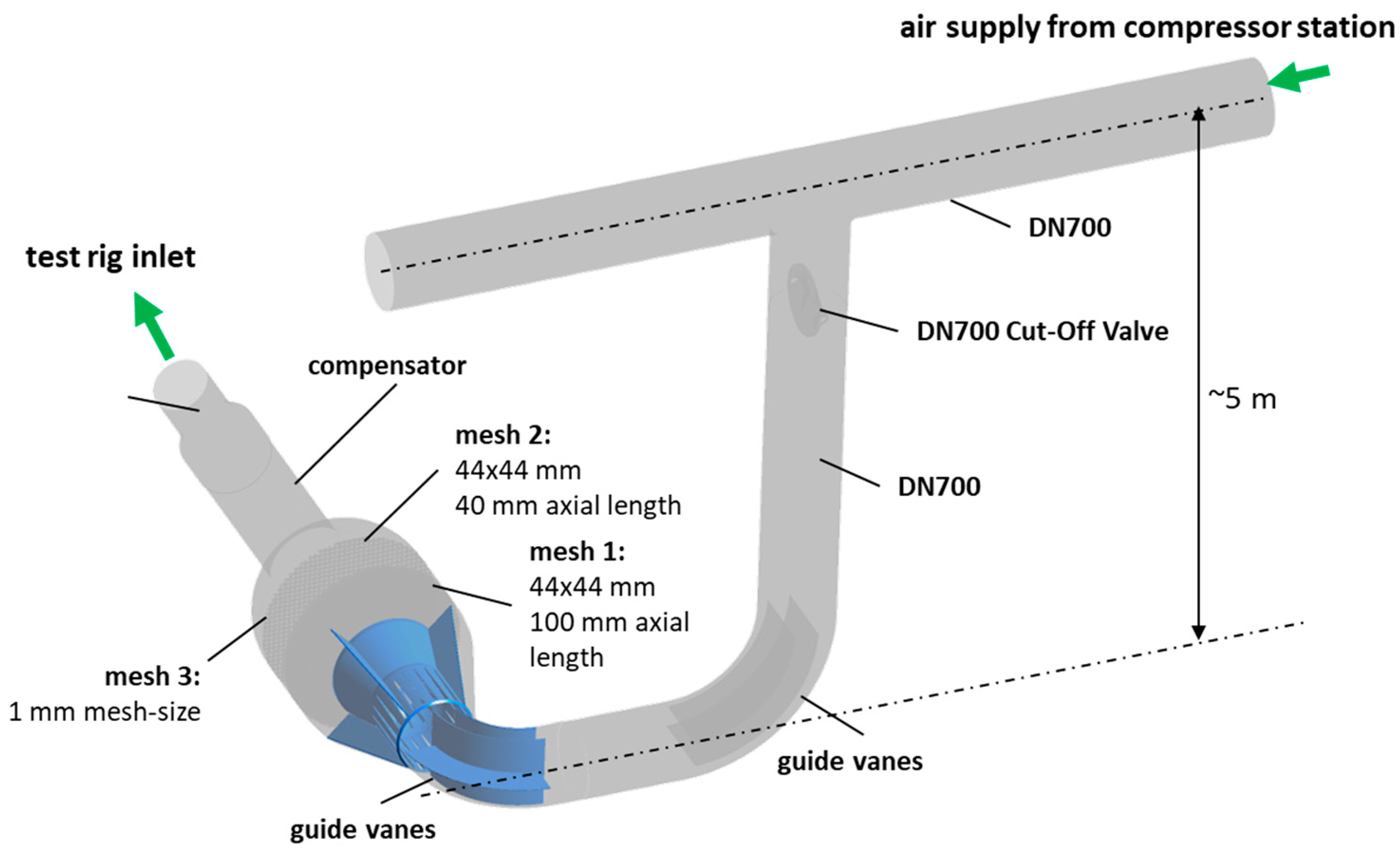
Figure 2 shows the position of the settling chamber in front of a standard test cell within the facility. Due to restrictions in the overall facility layout, the axial length is limited, as mentioned above. The test rig is fed compressed air from the supply line above the test cell. This means that the air passes the shut-off valve and, in total, three 90° bows before entering the settling chamber. The flow can be expected to be turbulent, while bows in different directions cause swirls and inhomogeneous flow profiles.
3.1. Mechanical Design
The settling chamber is part of an integrated piping system that has been designed to operate at pressure levels of up to 800 kPa and at more than 200 °C of static temperature. Thus, the settling chamber not only needs to fulfill aerodynamic criteria but also has to stand significant mechanical loads. The mechanical stress on several components puts additional constraints on the design to make sure that the system structure is stable, nonvibrating, and safe at all times.
As can be seen in
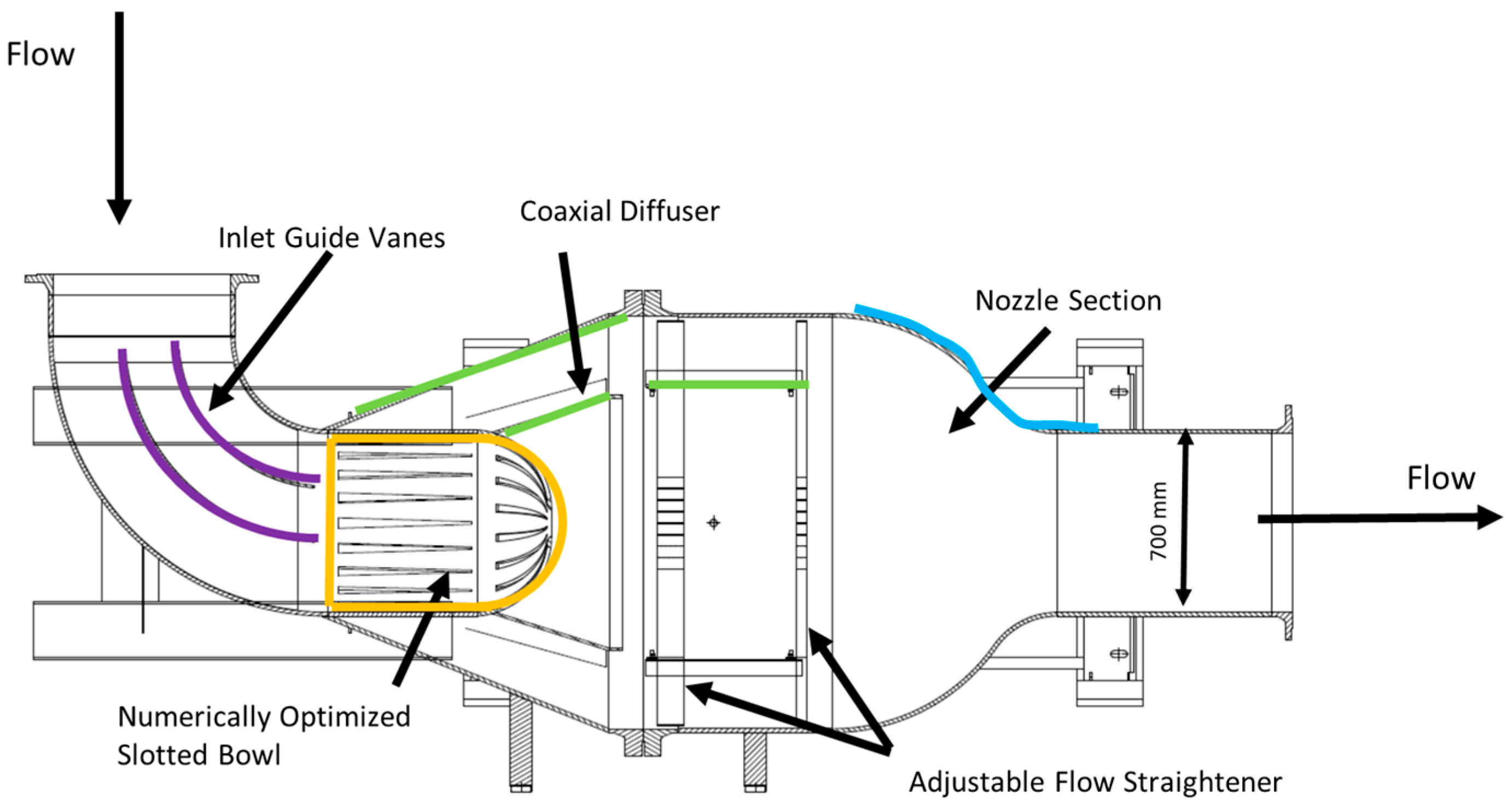
Figure 3, the starting point for the overall design was a standard pressure vessel [
9], including some guide vanes and several layers of meshes [
10]. The disadvantage of these types of designs is the unsymmetric flow distribution originating from the inlet section of the chamber in combination with the high amount of space needed for the dished ends of the vessel.
Due to the complex pipe geometry and the existence of several flaps and multi-axis bow elements upstream of the settling chamber, nearly one-third of the available length is covered by inlet guide vanes, turning the flow in a lateral direction. (compare
Figure 3). Due to the massive increase in cross-section, flow separation on the guide vanes occurs and can lead to local blockage and uncontrolled flow structures, which are then transported through the settling chamber.
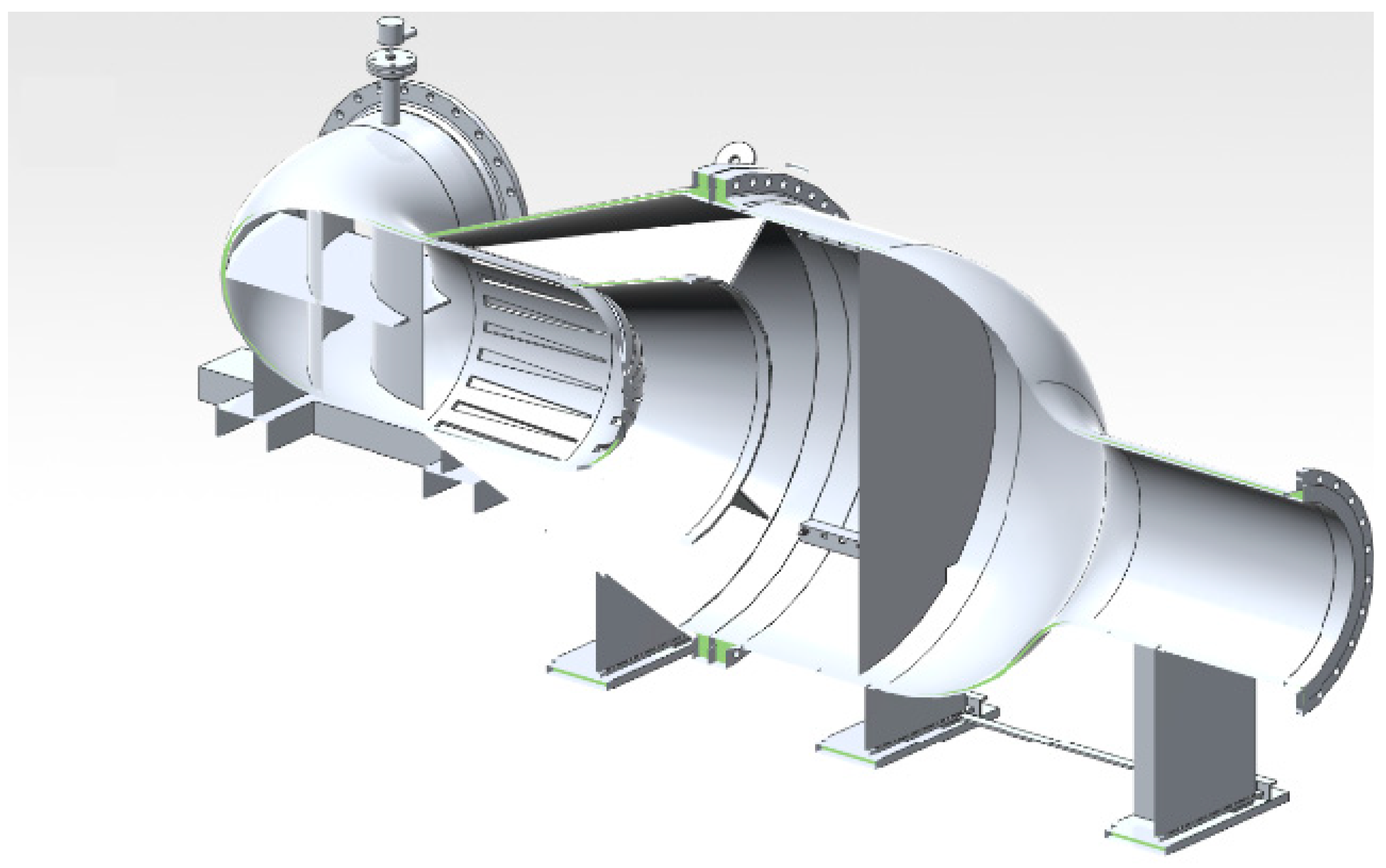
For flow homogenization, a mounting structure for up to three adjustable grating-type flow straighteners has been incorporated in the cylindrical part of the chamber. The gratings are equipped with wire screens on their upstream sides.
3.2. Aerodynamic Design
For the aerodynamic design of the settling chamber, the complete flow path between the supply line and the test rig has been optimized within the given restrictions.
Thus, geometry optimization has not only been conducted for the settling chamber itself but also for the piping system upstream of the settling chamber.
In order to aerodynamically stabilize the inlet section of the chamber, several iterative design steps have been performed. The final design can be seen in
Figure 3. Both bow segments upstream of the settling chamber are equipped with optimized internal guide vanes to reduce swirl and flow separations. The trailing edge of the guide vanes has been designed for a slightly overturning flow in order to achieve a mainly perpendicular flow pattern with regard to the inlet cross-section of the chamber.
Besides analytical overall methods ([
7,
11]), the main focus of the design optimization was on the slotted bowl, which has been designed instead of a flat bulging plate (see
Figure 4). This unique design has been optimized with regard to the overall geometry of the bowl itself as well as with regard to the geometry and the number of slots. The given design supports the axial as well as radial distribution of the flow within the inlet section of the settling chamber. Furthermore, the divergent section of the settling chamber is designed as a coaxial diffuser in order to reduce the risk of flow separation due to the aggressive cross-section extension in this part of the settling chamber. The support structure for the inner diffuser (“splitter cone”) acts as additional guide vanes to further suppress the swirl.
3.3. Flow Homogeneity Limits at Test Rig Inlet
The criteria for the evaluation of the settling chamber performance are mainly characterized by the maximum distortion of total pressure and total temperature field, velocities, and flow angles at the outlet section of the settling chamber. The limits related to mean values (except boundary layers) have been set to an allowed total pressure deviation of 0.1% of the mean value, or a maximum of 400 Pa. The allowed total temperature deviation has been set to 0.1% with a maximum of ±1 K. These limits are applied to all operating points as given in
Table 1.
3.4. Operating Conditions for the Acceptance Tests
A comprehensive analysis of the complete operating map of the air supply system has been performed.
Table 1 gives a survey of all operating points (OP) investigated. The points have been defined as charcteristig operating conditions for the assumed test rigts as well as reperesenting minimum and maximum operating conditions of the air supply system.
3.5. Numerical Model and Experimental Setup
Numerical Domain
During the design process as well as for the post-test analysis, a numerical model has been set up. The optimization was conducted using STAR CCM+ 11.02 at Leibniz University of Hannover as well as using ANSYS CFX 2022 R2 and OpenFoam at AERZEN. In the following, only results from the post-test analysis conducted with ANSYS CFX will be shown. A mesh study was performed for the discretization of the geometry and the flow volume, resulting in an unstructured mesh of 28,000,000 nodes. For high second-order accuracy, the “high resolution” discretization was used for the simulations. For turbulence modeling, the Menter SST model was used. As y+-values have been set to y+ > 100, boundary layers have been resolved by wall functions and have been assumed to be fully turbulent (no transition model).
Figure 5 shows the complete domain of the numerical model.
The overall boundary conditions were set to a given mass flow rate and stagnation temperature at the inlet while using a static pressure boundary condition at the outlet.
3.6. Setup and Operating Range for Experimental Data
For the recording of experimental data, a new measurement device has been developed to be used during the acceptance tests [
5]. The device consists of 12 rake probes for permanent measurement of total pressure and total temperature, with a total of more than 120 measurement positions. In addition, radially moving multi-hole pressure and temperature probes can be inserted into the flow. This enables the fast detection of the local flow field at the exit section of the settling chamber. While rake probes can be used to measure continuously at the complete cross-section of the core flow, traversing probes can be used to conduct high-resolution measurements of the core flow as well as for measuring the boundary layer near the walls. The device was developed and manufactured at Leibniz University [
5].
Figure 6 shows the schematic sketch of the measurement device as well as the device implemented in the piping system. A total of 19 operation points have been investigated, representing different load characteristics of the future test rigs.
4. Results and Discussion
As described in
Section 3, a detailed, iterative design process based on standard RANS simulations has been used to improve the internal aerodynamic design of the settling chamber. Therefore, internal mechanical guide vanes, throttle structures, and meshes have been installed and optimized. Due to limitations in available space, multiple distortion and vortex-generating structures can be found upstream of the settling chamber (twin-90-degree pipe bow, butterfly valve, etc.). The design efforts were mainly aimed at reducing inhomogeneous turbulence and swirl.
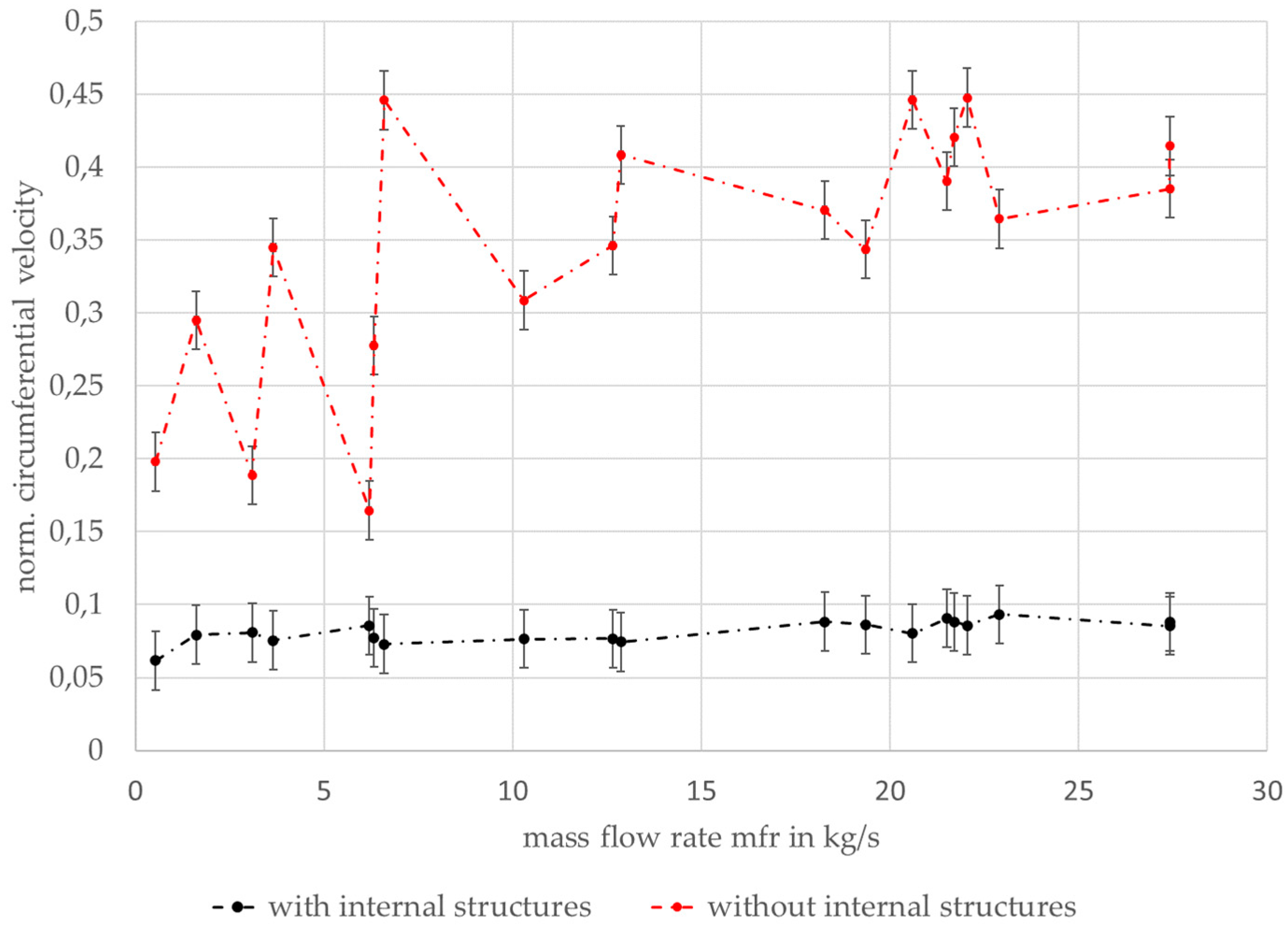
Figure 7 shows the effect of optimized internal structures on the swirl in comparison to an empty settling chamber with no internal structures. It can be clearly seen that a massive reduction in the normalized circumferential velocity can be achieved by the chosen design features. Despite an overall reduction in swirl for all operating points according to
Table 1, it can be seen from
Figure 7 that by using optimized internal structures, as shown in
Figure 4, the aerodynamic flow structures are much more independent from the operating conditions in general.
For the post-test analysis, OP5 and OP19, as given in
Table 1, have been investigated with regard to a comparison of the distribution of total pressure and total temperature within the core flow section. These operating points have been chosen for presentation because OP5 represents the operating conditions of most of the existing axial turbine test cases, while OP19 represents the upper limit of the new test facility itself, thereby defining the maximum operating parameters for future test applications. As the spatial resolution from the rake probe measurements is relatively low compared to the high resolution of the numerical simulation, all data from simulations have been reduced to the experimental grid in order to give a proper visual comparison of the data.
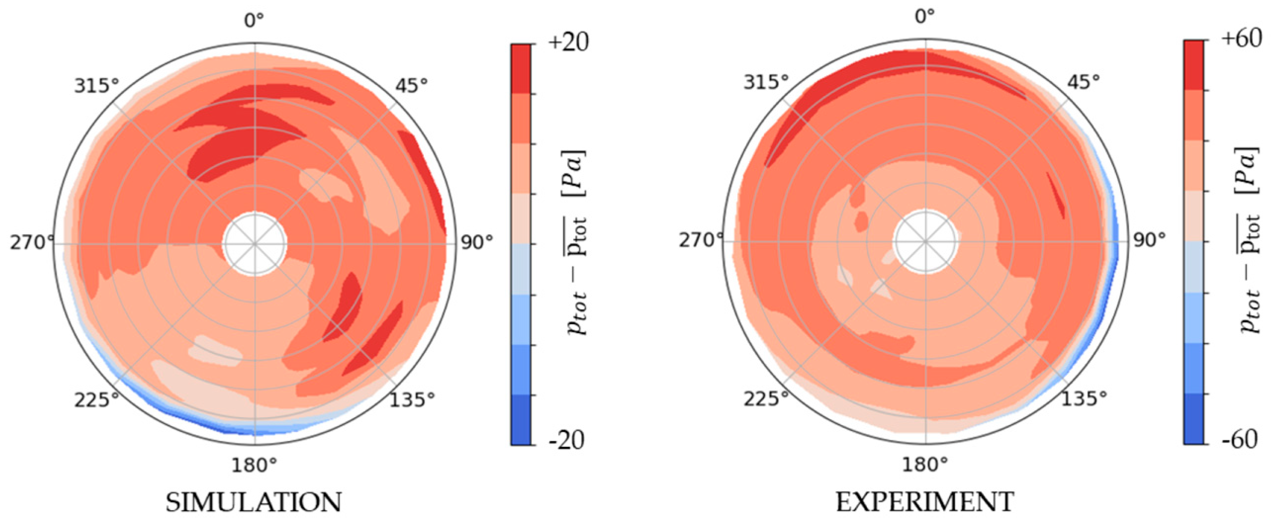
Figure 8 shows the relative total pressure distribution for OP5, representing a medium-load operating point for the facility and the settling chamber as well. It can be seen that the overall pressure distribution is quite good. The deviations in total pressure are clearly within the limits as given in
Section 3.3, for the simulation as well as for the measured data. As a matter of fact, the numerically predicted total inhomogeneity compared to the experimental data is smaller by a factor of 3, while the overall relative distribution shows a good match.
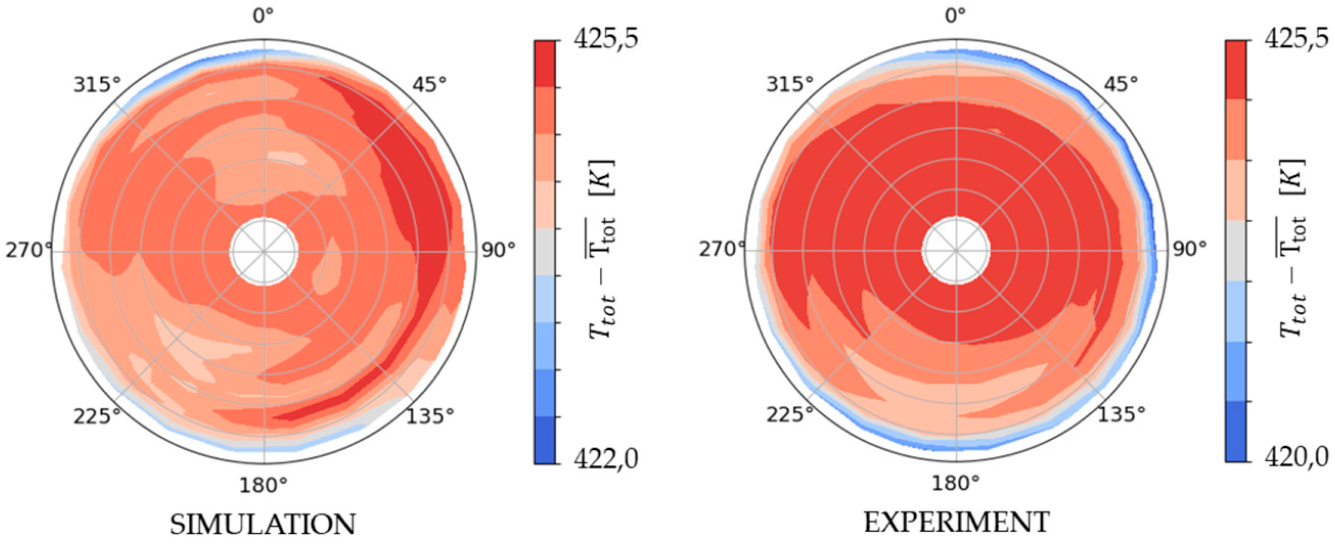
Pressure levels seem to be a bit higher in the upper part of the outlet pipe cross-section than in the lower part. The differences in the scale of total inhomogeneity are due to the lack of ability of RANS-based numerical models to give a good approximation of mixing processes. These mixing processes of turbulence and wake flow structures are often overestimated by the RANS models used. In addition, the measured data near the beginning of the boundary layer are very sensitive to errors in probe positioning. This might be an additional reason for the observed differences in near-wall regions. These arguments also account for the total temperature distribution shown in
Figure 9. It can be seen that the thermal boundary layer seems to be a bit larger than predicted. The size of the thermal boundary layer is, of course, very sensitive to the wall heat transfer. Although all pipes are thermally insulated during the measurement, the local heat transfer cannot be neglected. The actual wall temperature has been measured during the test, so for all temperature data shown in this paper, the numerical model has been adjusted to the real wall temperature of the piping components.
For the second operating point, OP19, the absolute inhomogeneity of the pressure flow field increases due to higher flow velocities, as can be seen in
Figure 10. The relative difference between the simulation and the measured data is at the same scale (factor 3–4) as for OP5. As already described for OP5, the pressure level in the upper part of the investigated pipe section is a bit higher than in the lower section but still at a very low level. This flow behavior can be seen in calculated data as well as in measured data. The total pressure boundary layer is larger than for OP5 due to different velocity profiles. Although the sensor positions near the pipe wall already seem to measure parts of the boundary layer profile, all pressure data are within the limits set for the overall settling chamber design.
Figure 11 shows the total temperature distribution for OP19. It can be seen that temperature boundary layers are larger than for OP5, especially for the measurements. On the one hand, the overall flow temperature for OP19 is higher than for OP5, which means a higher temperature gradient between the core flow and the wall. On the other hand, higher turbulence might cause higher mixing and, therefore, a stronger transport of cold air from the near-wall region to the center of the piping. The overall core flow at OP19 is also well within the given limits of ±1 K. In any case, further studies will give a more detailed view of the development of the temperature boundary layer.
To provide a more detailed view of the temperature distribution,
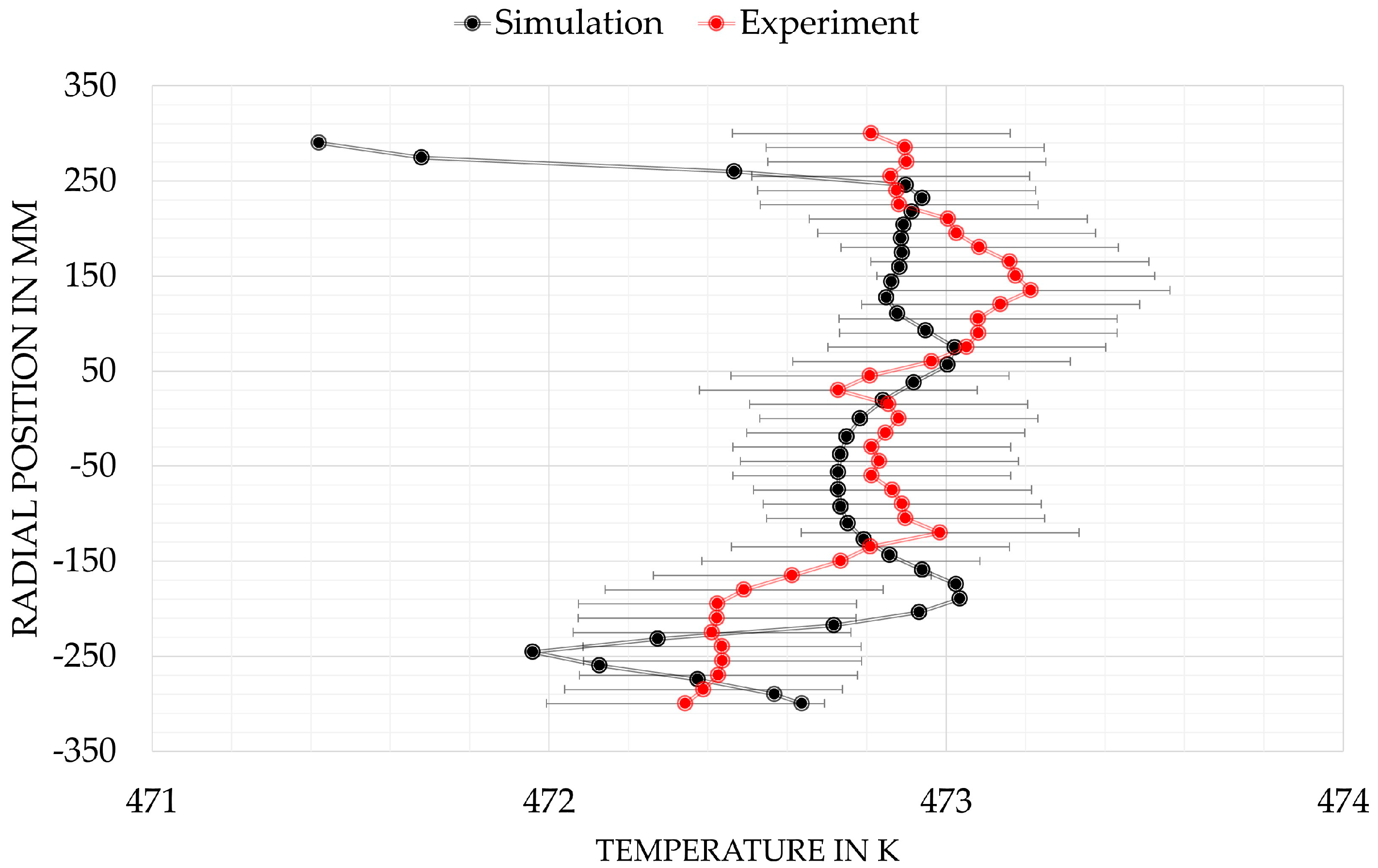
Figure 12 shows a comparison between the calculated temperature profile and the measured profile from a temperature probe traversing between the circumferential positions of 45° and 225° for OP19. Please note that there is no direct comparison between
Figure 11 and
Figure 12, as the resolution of the data, as shown in
Figure 11, is drastically smaller than in
Figure 12.
It can be seen that there is a very good match between the simulation and the measured data regarding the overall temperature level. In both data sets of
Figure 12, simulated and measured data, there is a very slight drift to higher temperatures within the profile for higher radial positions. As the fluid is directed in the horizontal direction when passing the settling chamber, the major flow direction is horizontal, which means that slightly warmer parts of the fluid convect to the upper part of the flow field. For the measured data, the measurement uncertainty is given in
Figure 12 as a benchmark for the quality of the flow.
5. Conclusions
A design approach for flow settling chambers for aerodynamic test rigs has been shown and experimentally validated. The authors can show that the use of state-of-the-art CFD tools is valid for the purpose of new settling chamber design iterations. By applying multiple flow straighteners upstream of the settling chamber itself, the authors can prove that disadvantages arising from the very limited axial length of these customized settling chambers can be equaled by individual concepts for the internal design, such as optimized slotted bowls and splitter cones. When analyzing numerical pre-test results, it should always be kept in mind that distortions in the flow field at the outlet section of the settling chamber will be predicted to be smaller than they are due to overestimated mixing by the numerical models.
Regarding the operating parameters, it can be stated that the chosen design is robust in terms of different pressure levels and mass flow rates and is well suited to provide a high-quality inflow to turbomachinery test rigs.


