1. Introduction
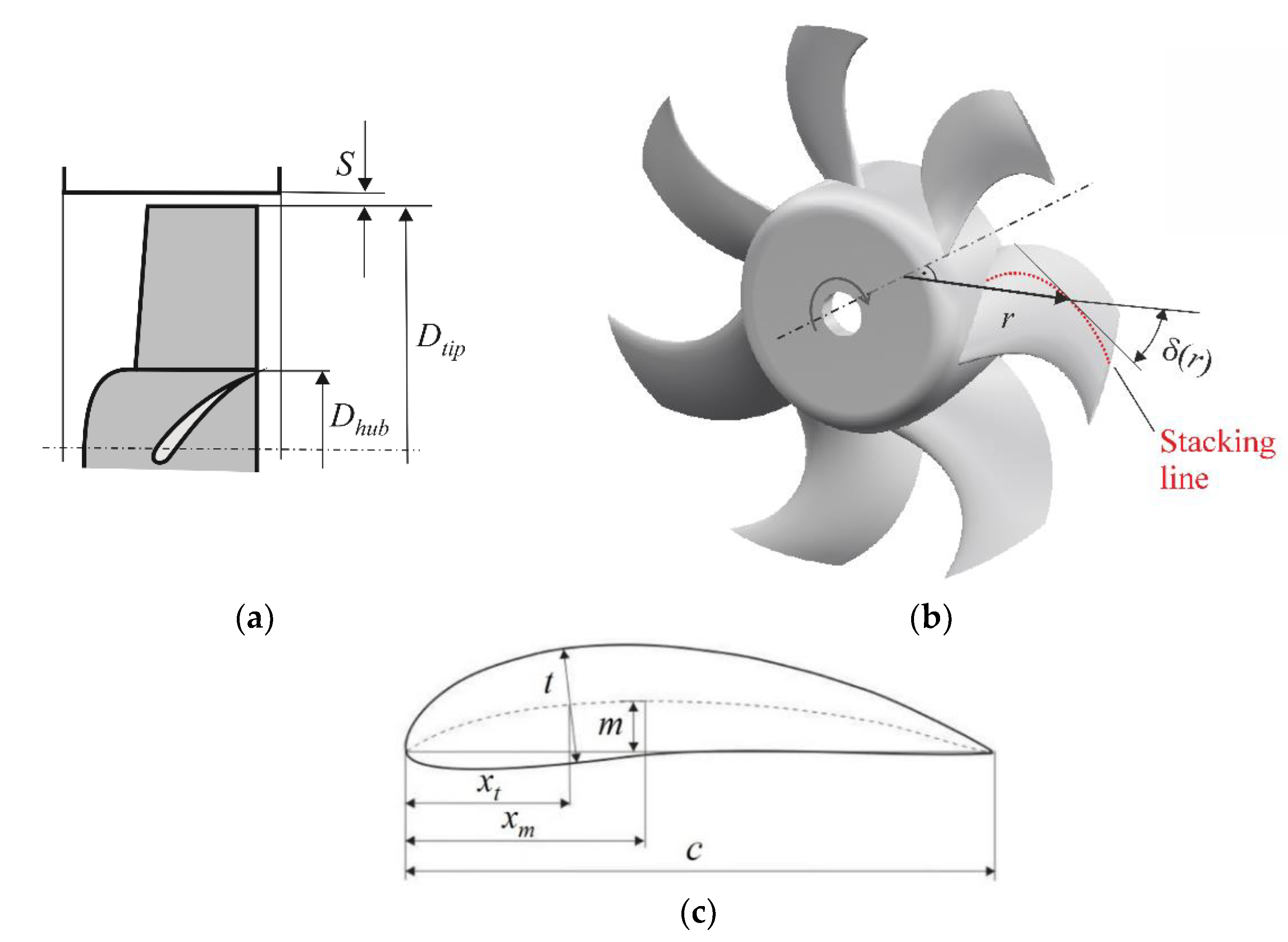
For several applications, the impeller-only axial fan in a duct-type casing is the preferred choice. Examples are dry cooling towers in thermal power plants, installations for locomotive and automotive engine cooling, railway and automotive air conditioning systems, heat pumps, etc. The appropriate hub-to-tip ratio of the fan impellers (
Figure 1) has been discussed for many years.
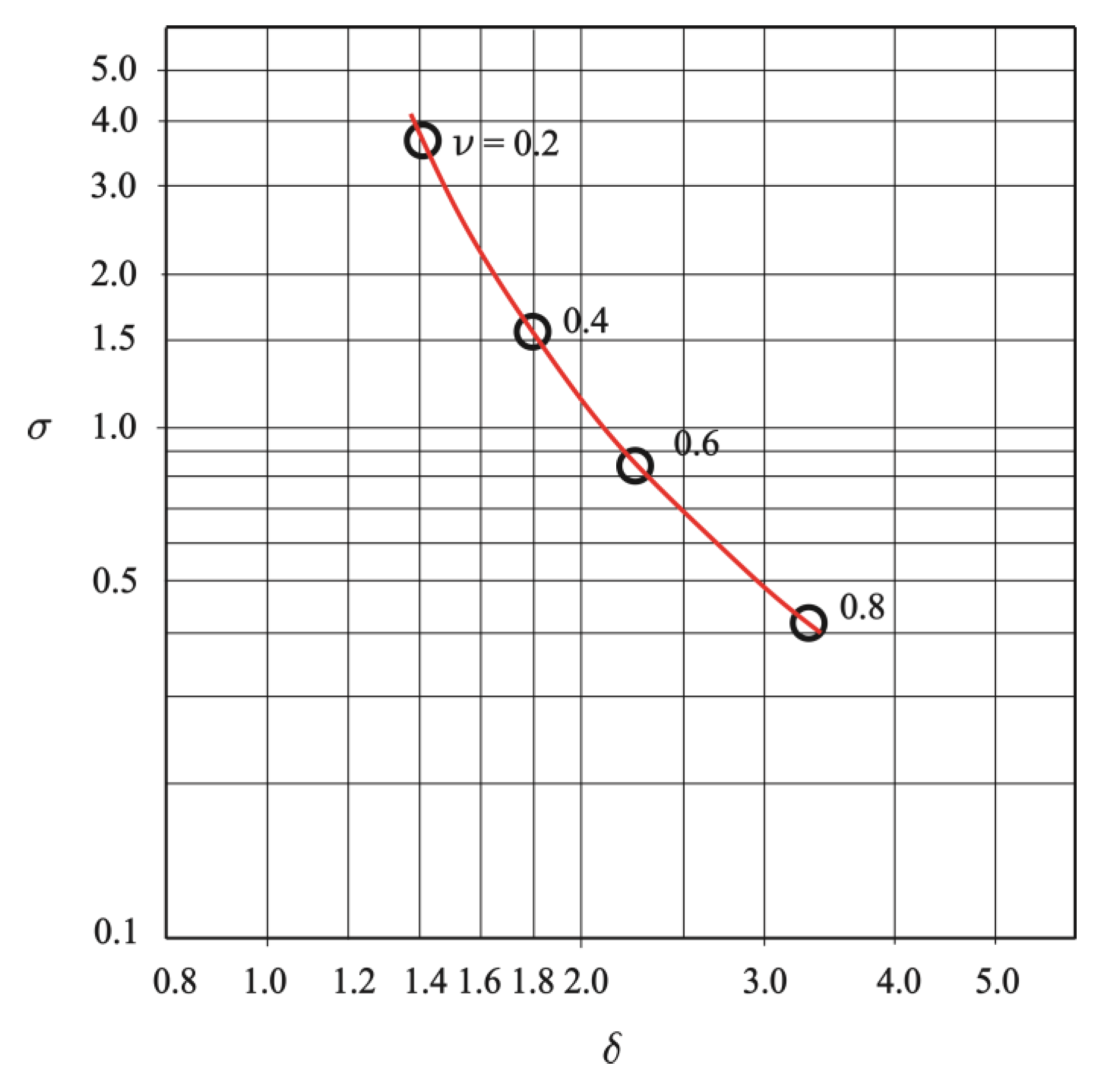
Figure 2 illustrates a historic example; the data is taken from the classic textbook by ECK [
1], 1972, where the recommended specific speed and diameter as well as the smallest hub-to-tip ratio of such fan impellers are given in the so-called Cordier diagram. Note that here and throughout this study, all values of non-dimensional coefficients refer to the optimal point of operation, i.e., the operating point of the performance characteristic, where the aerodynamic efficiency is maximal. The frequently used index “opt” is omitted for brevity.
From fundamental aerodynamic findings, early hints for the minimum hub-to-tip ratio had been established by Strecheltzky (see Horlock [
2], (p. 227), De Haller [
3], and Schiller [
4]). Nevertheless, designers frequently try to reduce the hub-to-tip ratio further. One driver is cost—a larger hub can be expensive. Another reason is reducing the blocked area of an impeller at stand-still. In automotive engine cooling units, for instance, the fan is mostly not running, as the outer airstream provides forced cooling at moderate and high speeds of the vehicle. A third argument is that too large a hub obstructs the throughflow through an up- or downstream installed heat exchanger matrix. This, however, is frequently incorrect. The near-hub sections of the blades on an inappropriate hub may experience or even generate a backflow which has the potential to increase the non-functional area of a heat exchanger.
Several authors worked on methods for designing impellers with a very low hub-to-tip ratio. For instance, Lindemann et al. [
5] suggested a design method for a small hub-to-tip ratio with swept blades, based on an empirical axial and tangential velocity distribution in the spanwise direction from hub to blade. In a more recent paper, Wang and Kruyt [
6] studied small hub-to-tip ratio fans. Among others, they analysed the influence of non-aerodynamically shaped parts of the blades and showed “that the presence of non-airfoil sections near the root has a minor influence on the pressure coefficient and hence on the total-to-static efficiency (of the fan), due the formation of a vortex upstream from the blades near the hub. Overall, the ‘main blade’ part well represents the aerodynamic performance.” The potential drawback in efficiency was not discussed in detail. Nevertheless, the idea in their subsequent paper [
7] was to quantify the potential of the overall blade sweep, dihedral, and skew on the aerodynamic performance of such fans. They found only minor benefits.
This study aims at determining highly efficient impellers with the minimum hub-to-tip ratio. The efficiency considered is the total-to-static efficiency which is an adequate metric for the energetic quality of the fan when it is the last component in a plant and exhausts directly into the free atmosphere or a large room. The dynamic pressure of the discharge jet constitutes the exit loss that is taken into account by the definition of this efficiency. In this study the dynamic pressure is associated with the flow velocity immediately downstream of impeller in the annulus formed by hub and cylindrical casing, not with the area of the complete rotor. This avoids the problem of taking into account a potential pressure recovery, e.g. due to a downstream tail cone or Carnot diffuser.
Differently from other studies, a holistic approach is chosen. Possible design points cover the complete range common for this class of fans. The radial, i.e., spanwise, distributions of the blade sweep angle, stagger angle, and chord length are varied to adapt the blades to the complex flow in the hub and tip regions. The tool being used is an optimization scheme developed and validated by Bamberger [
8]; see also Bamberger and Carolus [
9].
2. Methodology
2.1. Non-Dimensional Coefficients Used
In this study, the common definitions of non-dimensional coefficients are used.
Q (kg/m
3) is the volume flow rate, Δ
p (Pa) a pressure rise,
n (1/s) is the rotational speed of the impeller,
Dtip (m) is the rotor outer diameter (and approximately the clear diameter of the casing
D),
ρ (kg/m
3) is the (constant) density of the gas, and
P (W) the shaft power. The volume flow and pressure rise coefficients as well as the efficiency are defined as
The specific diameter and speed are:
ϕ and
ψ can be expressed in terms of
δ and
σ, and vice versa. Depending on the case of application,
ψ and
η can be defined using either the total-to-
total (index „tt”) or the total-to-
static (index „ts”) pressure rise. (In ISO 5801 [
10] the total-to-
total pressure rise is simply called the „fan pressure” with the symbol
pf; the total-to-
static pressure rise is called „fan static pressure”
pfs which must not be mistaken for the true static pressure rise of the fan.) The total-to-
total pressure rise Δ
ptt is a measure of the total energy transferred from the shaft to the fluid and equals the difference between the total pressure downstream of the fan and the total pressure upstream of the fan. In applications where the dynamic pressure downstream of the fan dissipates in the free atmosphere or a large room, the total-to-
static pressure rise Δ
pts (i.e., Δ
ptt diminished by the so-called exit loss) is more adequate to describe the design point, and
ψts and
ηts become the relevant dimensionless quantities. In contrast,
σ and
δ are always defined with Δ
ptt, with most probably an exception in
Figure 2, which will be discussed below.
The geometrical quantity which is most relevant in this paper is the hub-to-tip ratio (see
Figure 3a)
2.2. Optimization Scheme
A short summary of the optimization scheme is given in this section. Details can be found in [
8,
9]. Three key components are essential: (i) a database of performance characteristics of 14,000 different axial fan impellers, (ii) a metamodel for the fan performance as function of the impeller parameters varied, and (iii) an evolutionary algorithm as an optimization method.
2.2.1. Database
The database consists of the performance characteristics of 14,000 individuals in the class of axial fan impellers. It was created beforehand by an automated Reynolds-averaged Navier–Stockes (RANS) prediction.
Figure 3 shows the geometrical parameters varied. In
Table 1 the geometrical parameters are compiled which are varied throughout the optimization. It is important to note that the range of permissible hub-to-tip ratios has been limited to values between 0.3 and 0.7. This means in particular that there are no impellers in the database with a hub-to-tip ratio <0.3. The blades are composed of 4-digit NACA airfoil sections with the parameters “maximum thickness”, “maximum camber”, and their respective “chordwise positions”. The maximum blade thickness is fixed to 5% of the chord length, which may allow production in plastic injection molding.
Empirically, the optimal points of operation of common high-efficiency single-flow and single-stage centrifugal, mixed-flow, and axial fans lie—in terms of specific diameter
δ and speed
σ—in a relatively narrow band called the Cordier band; see the hatched area in
Figure 2. Guided by this Cordier band, Bamberger in [
8] fixed the sensible range of aerodynamic design parameters of axial impeller-only fans according to
Figure 4 and
Table 2, here in terms of
ϕ and
ψts. This design space is more or less adopted for the current study. Note that the range of aerodynamic design parameters is deliberately chosen to be broader than the conventional Cordier band suggests.
A sketch of the computational domain for the CFD simulations is presented in
Figure 5. The computational domain comprised one blade channel using periodic boundary conditions at the lateral surfaces. Further boundary conditions were: fixed mass flow at the inlet, ambient pressure at the outlet, and no slip at the walls. The turbulence was modelled using the
k-ω SST model. The solver was Ansys CFX™. Numerical grid generation and evaluation of the RANS results were automated. Combinations of a total of 26 geometrical parameters were determined systematically with a method of design of experiment (DoE). The resulting pressures were evaluated in plane 1 and 2.
Three minor constraints associated with the database thus obtained are:
2.2.2. Metamodel
The metamodel is based on an artificial neural network. It enables predicting the performance characteristics, including efficiency and the circumferentially averaged flow velocity in the impeller exit plane, of any impeller made of a reasonable combination of the 26 geometrical parameters. The neural network type selected is the multi-layer perceptron (MLP). MLPs consist of the input layer, an arbitrary number of hidden layers, and the output layer. The number of hidden layers and the number of neurons in each of them determines the model complexity. A too-simple model will lead to large errors because of insufficient flexibility. On the other hand, a too-complex model will suffer from overfitting effects, i.e., the error will be small on the training data but high on fresh data that was not used for the training. Therefore, the available data were split into training and test data, and the model complexity was optimized aiming at a minimal error on the test data.
2.2.3. Optimization Method
The actual optimization is performed on the metamodel. For optimization, an evolutionary algorithm is implemented. One essential advantage of evolutionary algorithms is their ability to find the global optimum, which is considered important for the present work. The main disadvantage compared to local optimization algorithms (e.g., gradient-based ones) is the high number of function evaluations that is required for convergence. Due to the extreme quickness of the metamodels, however, this disadvantage is less relevant for the present study. The main optimization target is always the maximization of ηts with the constraint that the targeted design point must be fulfilled.
The complete scheme is implemented in Matlab™ and requires standard PC computer resources only.
3. Results and Discussion
A systematic design of impellers in the design space yields the hub-to-tip ratios plotted in the upper plot of
Figure 6. For fans designed for large values of
ϕ and low to moderate values of
ψts (such as B), a lower hub-to-tip ratio could be feasible. As mentioned before, such a design has been excluded a priori because the initial training data for the metamodel were deliberately confined to the parameter range of
ν = 0.3–0.7. The maximum achievable total-to-static efficiency for each design is depicted in the lower plot of
Figure 6. Clearly, the fans with the highest efficiencies are those designed for
ϕ /
ψts pairs in the region of the lower left corner with a hub-to-tip ratio
ν ≈ 0.3–0.4 accordingly.
Selected fans (i.e., pairs of
ϕ and
ψts) in
Table 3 illustrate the results. In contrast to conventional designs, the optimization suggests blade shapes with an unexpected spanwise distribution of chord length, stagger angle, and especially sweep angle.
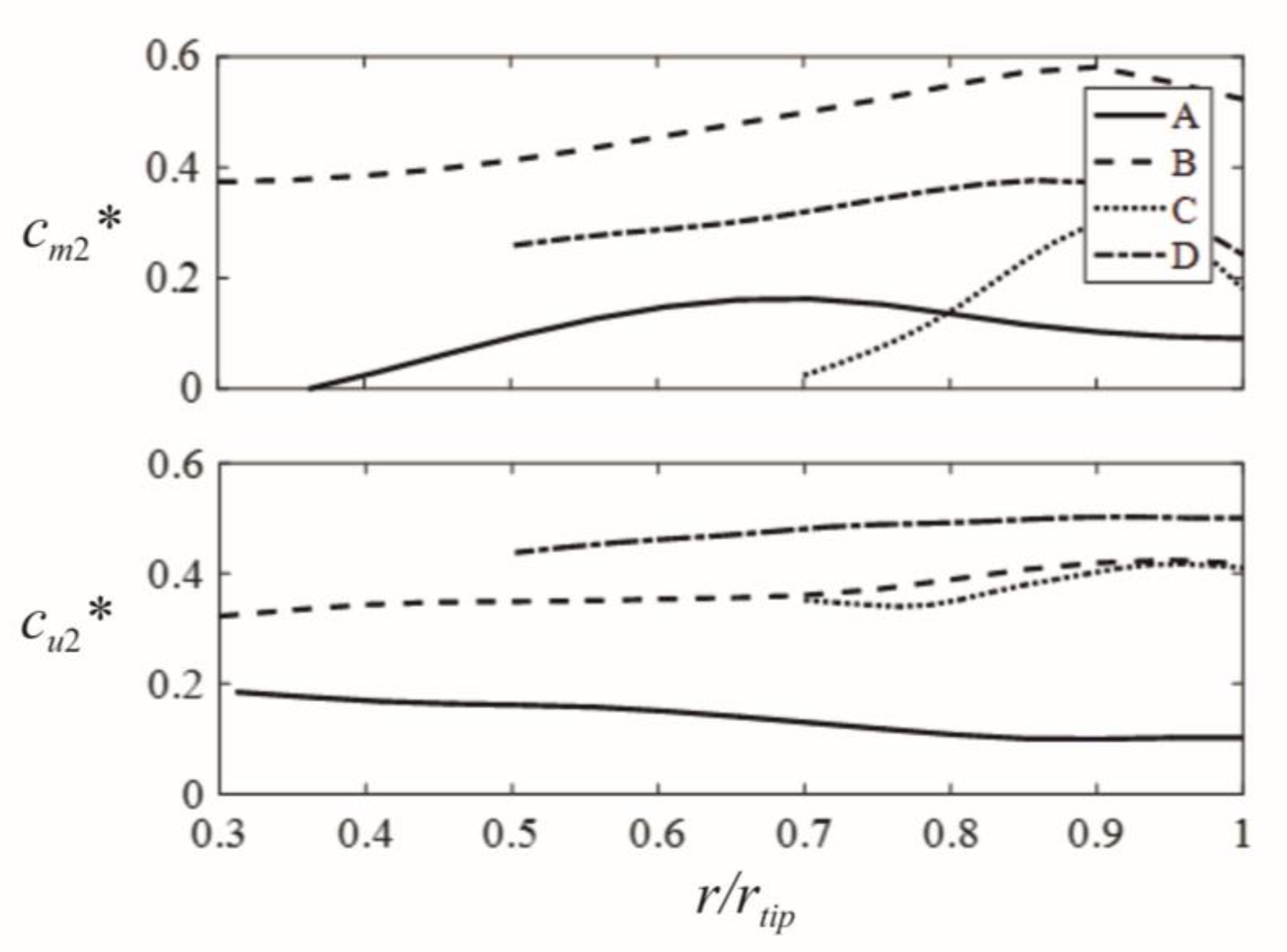
The metamodel also yields the circumferentially averaged flow field at the impeller exit, as shown in
Figure 7. Seemingly, the optimal blade shape causes a meridional velocity component at the fan exit
cm2, with a maximum in the middle or outer blade section. This means that the volume flow rate is not evenly distributed in the bladed annulus of the impeller. In the critical hub region the throughflow is reduced. The tangential velocity cu2, which is a measure of energy transfer to the fluid, is shown as well. In all graphs the velocities are normalized with the blade tip speed π
Dtipn, indicated by a star as a superscript. Despite a small region of backflow, the most efficient impeller is A.
For comparison, for the same design point as A, an impeller was designed employing a standard textbook blade–element–momentum (BEM) method, cp. [
13]. The hub-to-tip ratio was chosen as
ν = 0.31 as well. As an empirical assumption, the frictional loss at each elemental blade section along the span was set to 10% (corresponding to a local hydraulic efficiency of 90%)—possible additional losses in the blade hub and tip regions were neglected. Furthermore, a volumetric loss in the tip gap region was neglected as well. A free vortex distribution was chosen which—in agreement with the requirement of radial equilibrium—results in
r x
cu2 =
const and
cm2 =
const along the span. In
Figure 8, these
r x
cu2– and
cm2–distributions are compared to those from the optimal impeller A. Both velocity distributions show distinct differences. This is due to the fact that the optimization method, which is based on comprehensive CFD data, takes into account all local losses. No assumption for the local efficiency is necessary. The optimizer even predicts the overall achievable efficiency. Moreover, the optimizer identifies those spanwise
cu2– and
cm2–distributions which are associated with the minimum overall dynamic pressure at the impeller exit, i.e., the minimum exit loss. Note that the classic free vortex distribution is not optimal with respect to the exit loss; the axial exit flow velocity is constant, but the tangential varies substantially from hub to tip:
cu2 (
r) =
const/
r. Hence, it is understandable that the overall dynamic exit pressure, which is based on the integral of the squared exit velocities from hub to tip, can be minimized by choosing optimal
cu2(
r)–and
cm2(
r)–distributions. In general, those distributions will deviate from the classic free vortex design. Eventually, the blades which provide that optimal exit flow are characterized by complex distributions of chord length, as well as stagger, sweep, and dihedral angles.
It is important to note that the chosen hub-to-tip ratio for the textbook design was by far below the classic limits according to Strecheltzky, De Haller, and Schiller. This is a general observation: the hub-to-tip ratios suggested by the optimization scheme are always smaller than those obtained according to the classic rules. This even applies to ECK’s recommendations, initially shown in
Figure 2. (Some caution is necessary when interpreting
Figure 2 qualitatively; most likely ECK obtained the Cordier-curve defining
σ and
δ with Δ
pts and not Δ
ptt, as is customary today.)
4. Conclusions
The objective of this study was the design of impeller-only axial fans with optimal hub-to-tip ratios for highest achievable total-to-static efficiency. This in contrast to other studies, where a primary design target is a very small hub at the potential expense of the efficient aerodynamic function of the near-hub blade region.
Differently from other studies, a holistic approach was chosen. Firstly, the complete class of these fans is considered, not only one particular design case. Secondly, an optimization method is applied, which allows determining the optimal hub-to-tip ratio, the radial distribution of the blade sweep angle, the stagger angle, and the chord length. The classic hub-design rules by Strecheltzky, De Haller, and Schiller need not to be applied.
In general, the hub-to-tip ratios for the class of axial impeller-only fans proposed by the optimization scheme are smaller than those obtained applying the classic rules. It should be pointed out again, however, that the permissible hub-to-tip ratios have been limited to a range of 0.3 to 0.7. In particular, this means that impellers with hub-to-tip ratios <0.3 cannot to be expected with the scheme used here. In the case of impeller B, whose hub-to-tip ratio is exactly 0.3, the selected lower limit of the permissible hub-to-tip ratios may have acted as a non-physical limitation.
A second outcome are the shapes of blades, which are adapted for minimum exit loss. These shapes deviate substantially from the classic and even the state-of-the-art “swept-only” or “swept with dihedral” designs: the chord length, stagger, and sweep angle are distributed from hub to tip in a complex manner. The inherent reason is that the scheme tries to minimize not only the overall dynamic exit loss, but also frictional losses due to secondary flows in the hub and tip regions.
Essentially, the optimization method used is based on RANS simulations. In the past the underlying RANS method has been validated for several examples. Nevertheless, the authors do provide the full geometry of the four impellers A, B, C, and D to any individual for experimental validation or further analysis of their performance (see data availability statement below). This would also allow comparison with commercial fans with similar performance parameters, but whose hub-to-tip ratios are smaller than those proposed by the method used.


