To investigate the effect of the stage gap, the axial distance between the rotor and the stator was reduced to
of the designed value, and its effect on the performance and the variation of flow characteristics studied numerically. For the back pressure producing the designed mass flow rate at the designed gap, simulations at the other three moderate gaps were also be performed at the same back pressure in order to examine whether the variation of aerodynamic performance was consistent if the row gap continuously changed. The relative positions of the rotor and stator at the designed gap and its 10% are shown in
Figure 9a,b, respectively. Note that the axial distance from the rotor’s trailing edge and the stator’s leading edge on the hub surface was measured as the gap distance in this paper, and the designed value denoted by
, i.e.,
. Reduction to the axial gap was achieved by adjusting the axial location of the stator with the rotor fixed. Specifically, the 5-level mesh on the hub surface for the smaller gap, i.e.,
, is presented in
Figure 10. Generation of a high-quality mesh at such a small gap is challenging to the traditional body-fitted approach, while it can be easily modeled by the IB method. As can be found from
Figure 10, there were still about 12 cells in the streamwise direction from the rotor’s trailing edge and the stator’s leading edge on the hub surface. The spatial scheme used in the present study required the first two closest layers of cells near the blade in the fluid domain to be marked as boundary cells, and their forcing points, thus, were always located near the third closest layer of cell near the blade. Therefore, even for the smallest-gap case, shown in
Figure 10, the impositions of the boundary condition for rotor and the stator would not influence each other. Moreover, for the designed cases with 10% gaps, the corresponding axial distances from the rotor’s trailing edge and the stator’s leading edge at the tip region were
and
, respectively.
3.1. Overall Performance at Different Gaps
Figure 11a,b show the comparisons of the total pressure rise and the adiabatic efficiency at two gaps,
and
, respectively, It can be seen, at each back pressure considered, the mass flow rate, the total pressure rise and the efficiency were all observed to be higher at the smaller gap, indicating that performance enhancement could be obtained through reduction of the stage gap. Cases 1–3, marked in
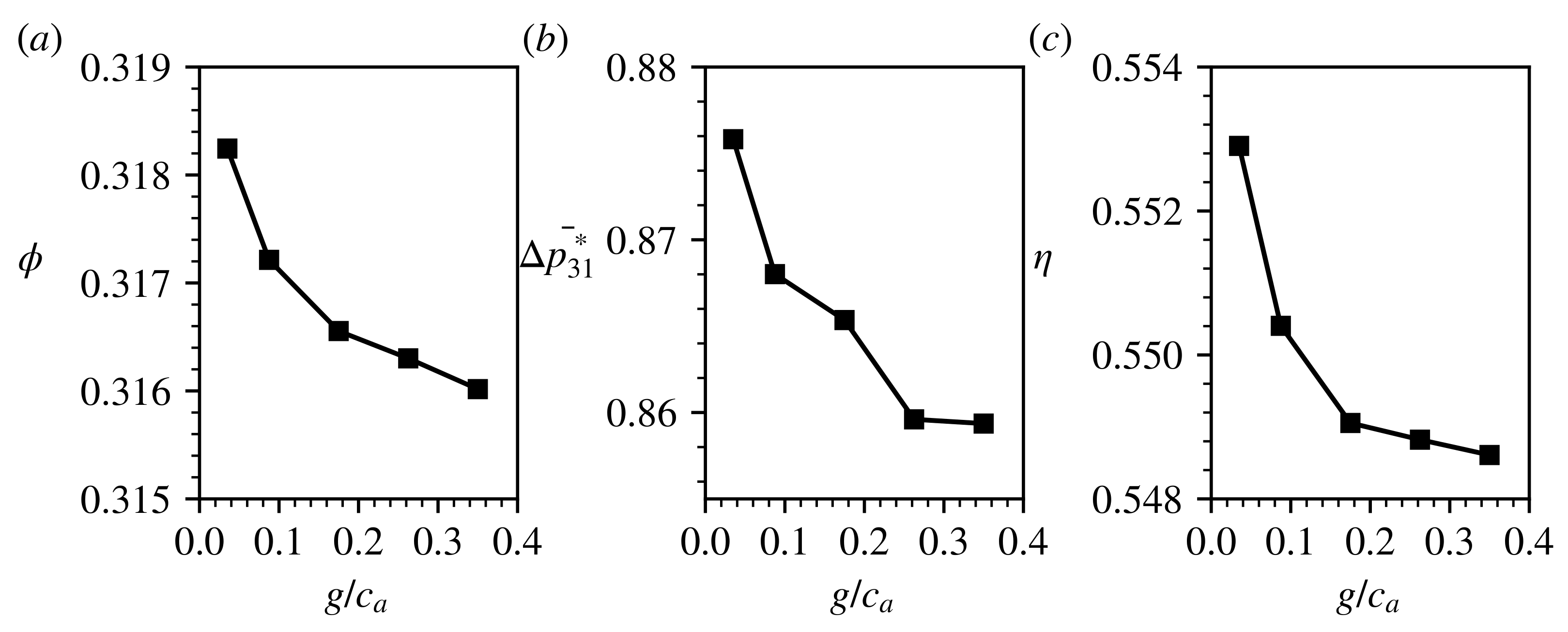
Figure 11a, were near the designed working point of the compressor. Cases 1 and 2 had the same back pressure but different gaps, the flow coefficients of which were 0.316 and 0.318, respectively. For cases 1 and 2, reducing the gap from
to
resulted in increases of
,
to the flow coefficient and the total pressure rise of the stage, respectively. Besides this, the stage efficiency also increased by
. To further demonstrate the effect of row gap under the same back pressure, cases 1 and 2 simulations were also conducted at the other three moderate gaps between
and
at the same back pressure.
Figure 12 shows the variation of the aerodynamic performance as a function of the blade–row gap. As the row gap continuously reduced, higher mass flow rate, total pressure rise and efficiency could be observed, suggesting the dependence of the aerodynamic performance on the row gap was consistent at the designed working point.
For a subsonic compressor, the mixing loss of rotor wake can be reduced when the gap becomes smaller, which was used to explain the generation of performance benefit by Smith [
3], Adamczyk [
4]. Du et al. [
10,
11] reported a vortex lift mechanism due to the blade–row interaction and the rotor loading was observed to be higher at a smaller stage gap. Therefore, both the flow variations of the rotor and the stator make some contributions to the performance enhancement of the compressor stage after the gap is reduced. Separating the contributions from the rotor and the stator was the main purpose of this work, which might be challenging in experiments because measurements at a narrow gap are normally not allowed.
In the following, comparisons are made for the results of cases 2 and 3, the flow coefficients of which were both 0.318. To quantify the contributions of the two blade rows to the performance enhancement individually,
Figure 13 shows the time profiles of the total pressure rise on the rotor and the stator outlets, as well as the axial torque of the rotor blade for cases 2 and 3, where their time-averaged values are also plotted through the horizontal dashed lines. It is remarkable that when the gap reduced, their averaged values also appeared to be higher, and increases of
and
were observed for the averaged total pressure rises on the rotor and the stator outlets, respectively, as shown in
Figure 13a,c. Correspondingly, the averaged axial torque on the rotor blade, shown in
Figure 13b, was also found to increase by
, confirming that the rotor worked at a higher-loading state when the gap reduced. It is noticeable that the benefit from the stator was more outstanding than that from the rotor. The following discussion reveals that, besides the contribution of wake recovery in the stator, the flow separation near the stator hub is well suppressed through the reduction of the stage gap, which results in a great influence on the performance of the stator. The higher pressure in the stage gap due to the increase of rotor loading plays a significant role in the suppression of the flow separation.
Note that the outlets of the rotor and the stator were located at and downstream of their trailing edges, respectively. The rotor outlet was also treated as the stator inlet. Since the variation of gap was achieved by adjusting the axial location of the stator, when the gap changed, the distance from the stator inlet to the stator was slightly different, and this effect was slight as the analysis mainly focused on the quantities of the outlets of the rotor and the stator.
3.2. Spanwise Distributions of the Performance Enhancement
The ratio of performance enhancement for the rotor between cases 2 and 3 appeared to be much lower than that reported by Du et al. [
10,
11] through 2D simulations. Since the stage gap was non-uniform along the span, as shown in
Figure 9, the benefit of reducing the gap might also differ along the span location. To demonstrate this dependence,
Figure 14a,b show the spanwise distributions of the averaged total pressure rise on the rotor and the stator outlets, respectively, which were obtained by firstly averaging the transient data along the pitch at each moment and then in a blade-passing cycle. Note that all the spanwise distributions in the following were obtained in this manner without additional mention. To further quantify the differences of performance along the span,
Figure 15a also shows the incremental ratios of the total pressure rise on the two planes as the gap reduced. It can be seen from
Figure 14 that the variations of performance were obvious in the low-span regions, i.e.,
, for both the rotor and the stator after the gap reduced. The contributions from the rotor and stator, as well as the corresponding flow variations, were of particular interest and the following discussion focuses on this aspect.
On the rotor outlet, reducing the gap to
resulted in increases of
for the total pressure rise in the range of
, as shown in
Figure 14a and
Figure 15. In contrast, the benefit in the rest of the span locations was negligible and even negative. Such a variation on the rotor outlet was well related to the nonuniform gap size along the span. Although the gap reduced to an extremely small value at the hub, as shown in
Figure 9, the tip region still worked with a considerable gap, i.e.,
, and, thereby, the rotor performance in the tip region did not exhibit much difference. This clarified that when the gap became small, the spanwise distribution of the gap could be determined well by the 3D blade geometries of the adjacent blade rows. The increase of the total pressure rise in
Figure 14a after the gap reduced also suggested that the rotor loading could be enhanced through reducing the gap. Chung and Wo [
50] conducted a study to split the potential and the vortical effects at different blade–row gaps and found that the potential effect was important, especially after the gap was less than
blade chord. Therefore, in the present case, after the gap reduced to
, the potential effect from the stator might play a significant role in the pressure distribution in the stage gap; thus, affecting the rotor loading. The potential effect is an inviscid mechanism and excludes the effect of vortex shedding. Du et al. [
10,
11] found the vortex shedding would also be enhanced when the gap reduced, associated with higher instantaneous rotor loading. Quantification to the contributions of the unsteady vortices and the potential effect on the rotor loading enhancement will be an important topic in our future study.
On the stator outlet, with the gap reduced to
, the total pressure rise was found to increase in all the span locations, as shown in
Figure 14b. Specifically, the enhancement was remarkable in the range of
, as shown in
Figure 15, and its maximum ratio was close to
, which was located in 20∼25% span. At these lower span locations, the corresponding ratios were all observed to be higher than
. In contrast, the increase of the total pressure rise was most insignificant in the range of
, which was lower than
. To further explore the source of performance enhancement in the stator,
Figure 15b provides the spanwise distributions of the total pressure loss coefficient between the outlets of the two blade rows at the two gaps. It can be seen from
Figure 15b that, after the gap reduced, the reduction of the total pressure loss in the span range of
was remarkable. Since the enhancement of the stage performance in this span range was far beyond the contribution of the rotor, see
Figure 14, the contribution from the stator, thus, might be the major factor. The total pressure loss in other span locations also decreased after the gap reduced; however, only to a minor extent. Smith [
1] reported a
∼
increase in the static pressure rise for a low-speed compressor when the gap was reduced from
of the chord to
. This increase could be explained by the theory of wake recovery, which was attributed to the reduction of the mixing loss of the rotor wake by Smith [
1,
3], Deregel and Tan [
5] and appeared to be more obvious when the flow coefficient became lower. In the present study, as discussed in the last section, the target flow condition was far behind the stall point, but the increase of the total pressure rise on the stator outlet was found to be
, which was almost twice the lowest measured value in Smith [
1]. Analysis of the spanwise pressure distributions in
Figure 14 and
Figure 15 revealed that it was the outstanding enhancement at the stator hub region that resulted in such a higher overall ratio on the stator outlet. The higher increase in the stator hub region suggested some different flow phenomena might exist, which resulted in a great reduction of the total pressure loss. On the other hand, the benefit ratio in the range of
at the stator outlet was close to the experimental data reported by Smith [
1], and the reduction of the total pressure loss after the gap was reduced was also slight, indicating the wake recovery process was dominant in the performance enhancement in this span range.
3.3. Flow Mechanism
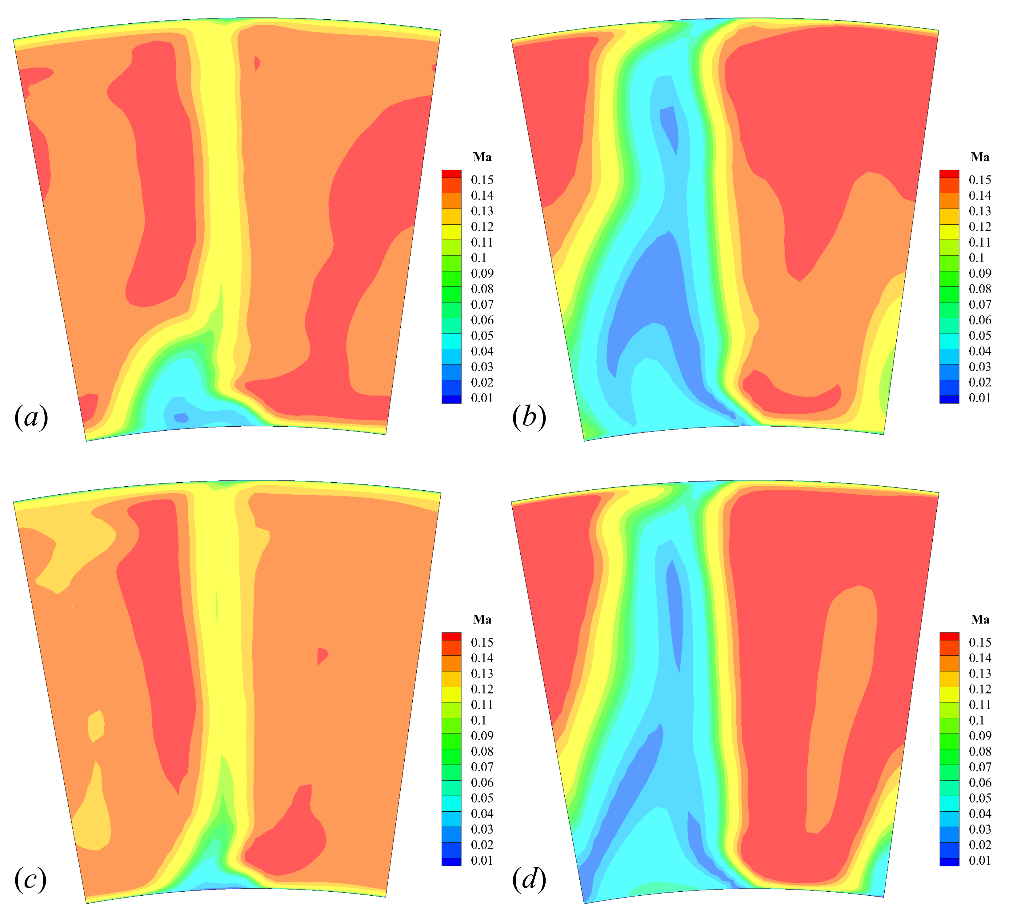
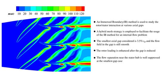
To explore the generation of performance enhancement from the two blade rows,
Figure 16 and
Figure 17 show the instantaneous distributions of Mach number and turbulence viscosity of the same moment for the two different gaps, respectively, at the same flow coefficient investigated. These flow contours were visualized on the
and the
span sections, as representatives for the shroud and the hub regions, respectively. As shown in the second column of
Figure 16 and
Figure 17, the flow contours at the extremely small gap were also smooth and did not suffer from the discontinuity generated by the blade–row interfaces encountered in the body-fitted approach, indicating that the IB method could be well applied to simulations of multi-row models with small gaps. For the two gaps, their flow characteristics on the
span section seemed to be similar, see the comparisons of the first row in
Figure 16 and
Figure 17, respectively. When the gap was reduced, it was noticeable that higher turbulence intensity could be observed when the rotor wake impinged on the stator in the smaller-gap case at both the shroud and the hub regions, see the areas marked by the red dashed circles in
Figure 17b,d. In the studies of Du et al. [
10,
11], it was found that when the gap was small, every time a rotor blade swept over a stator blade, a strong unsteady vortex shed from the trailing edge of the rotor blade, thus, increasing the oscillation amplitude as well as the mean value of the lift of the blade. Normally, flow turbulence intensity can be well enhanced by vortex structures as the magnitude of vorticity is part of the source term in the governing equation of the SA turbulence model. After the unsteady vortices shed from the rotor blade impinge on the downstream stator blade, the turbulence intensity might be further enhanced. On the other hand, higher velocity gradient was formed along the direction of the rotor wake when the gap was reduced, see the comparison of
contours in
Figure 16, which might also play a significant role in the increase of turbulence intensity of the rotor wake.
Figure 16 and
Figure 17 show that the reduction of the gap greatly impacted the flow structures at the hub region. At the designed gap, flow separation could be observed in the stator hub, as shown in
Figure 16c and
Figure 17c. Such a phenomenon is widely encountered by high-loading compressors [
51]. However, this separation is well suppressed in the smaller-gap case, as shown in
Figure 16d and
Figure 17d. As regards the authors’ acknowledgement, such an effect of reducing gap has not been reported yet in any experiment or simulation. This might be due to the fact that the smallest gaps considered in previous numerical studies, e.g., Hsu and Wo [
16], Przytarski and Wheeler [
17], were limited by the body-fitted grids and significantly larger than that of the present work.
Figure 18 also shows the distributions of Ma at the two gaps on a downstream section
to the stator’s trailing edge. Besides the case of
, the contours at
were also included, as a representative for the near-stall condition. It can be seen from
Figure 18a,c, flow separation existed in a small region near the stator hub at
and the reduction of the gap almost suppressed all the separation in the hub region. When the compressor worked at the near-stall point, although flow separation still existed in all span locations after the gap was reduced, both its width in pitch and the areas with the lowest Mach number were observed to shrink, as shown by the comparison of
Figure 18b,d, indicating the effect of suppression to the flow separation still played a significant role at the near-stall condition after the gap reduced. It is known that RANS models always fail to accurately capture details of separated and tip leakage flows without additional modifications. However, the results in
Figure 5a suggest that this inaccuracy was insignificant in the prediction of the compressor performance, as the numerical results did not exhibit much difference with the experimental data. Actually, RANS models are still widely used to study compressor flows. Although the flow separation in the stator was one major aspect of the present study, what we wanted to highlight was the dependence of this separation on the gap. The details of the separated flow, e.g., the spanwise length of the region with separation, obtained by the numerical study might be different from the reality, but the overall tendency observed with a reducing gap is still inspiring.
To further analyze the cause of suppression to the flow separation, the spanwise distributions of the flow velocity and static pressure on the outlets of the rotor and the stator were investigated.
Figure 19 shows the spanwise distributions of the three non-dimensional velocity components on the rotor outlet at the two gaps. The reference for the velocity components shown in
Figure 19 is
. It can be seen that the three components almost remained the same in all span locations when the gap reduced, suggesting that the inlet-flow angles of the stator at the two gaps were also close to each other. Therefore, the suppression to the flow separation in the stator was not due to the change of the inlet-flow angle. It can be observed in
Figure 14a that the total pressure rise at the hub region of rotor increased after the gap reduced. Since the velocity distributions on the rotor outlet at the two gaps were almost the same, it, thus, could be inferred that most of the increase of the total pressure was due to the rise of the static pressure on the rotor outlet.
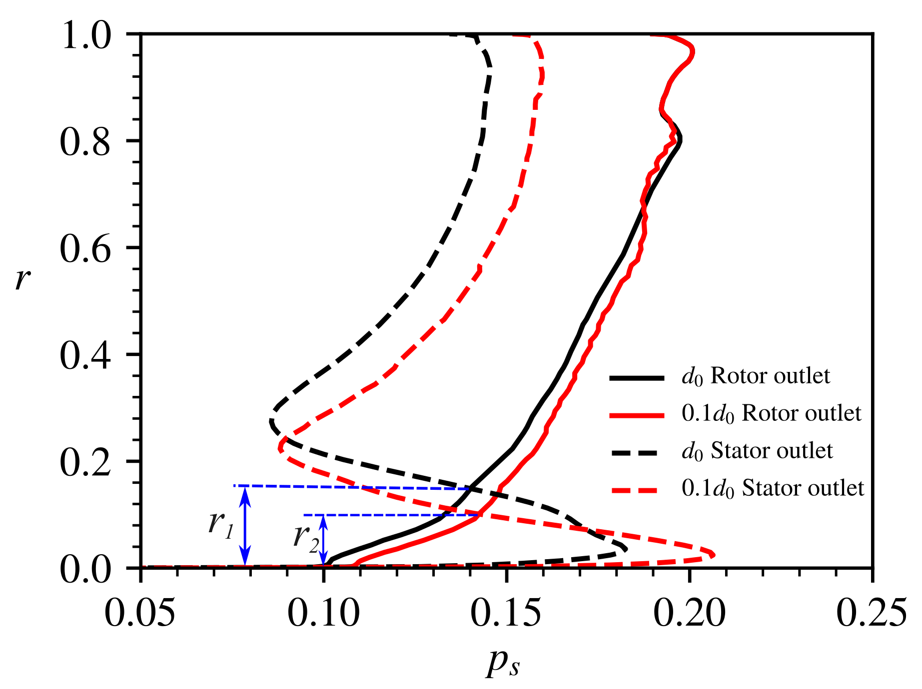
Figure 20 shows the spanwise distributions of the static pressure on the rotor and the stator outlet for the two gaps. It can be confirmed that the static pressure on the rotor outlet was found to increase in most span locations as the gap reduced. The difference between the static pressures on the inlet and the outlet of the stator in
Figure 20 revealed that the flow experienced an adverse pressure gradient in the hub region of the stator, which was related to the separation.
and
in
Figure 20 are used to denote the height in span of the region with adverse pressure gradient at
and
, respectively. Due to the increase of the static pressure in the stage gap after the gap reduced, the region with adverse pressure gradient was found to shrink, i.e.,
. This improvement compressed the separation region, thus, further reducing the total pressure loss in the stator hub region and resulting in a great enhancement to the performance of the stator. To further demonstrate the flow variation on the stator outlet,
Figure 21 shows the spanwise distributions of the three velocity components on the stator outlet, which are normalized by
. Prominent differences can be observed for the flow velocity near the hub, especially for the axial and the radial components in
Figure 21a,c, respectively, and both the components were found to be higher in the smaller-gap case. These differences of flow velocity suggested that the mass flow rate increased in the stator hub region and the blockage caused by the flow separation improved. In addition, the circumferential components, shown in
Figure 21b, were close to zero at all span locations at the designed gap, and only exhibited slight differences when the gap differed.
From
Figure 19,
Figure 20 and
Figure 21 it can be found that over most of the span, the stator was accelerating the flow and decreasing the pressure, which was an unexpected behavior for a compressor stator. Normally, the stator of a compressor should both change the flow direction and increase the static pressure. However, for the present stator working in a low-speed compressor, it was designed mainly to change the flow direction with a very weak capacity of increasing the static pressure. As can be seen from
Figure 4, the flow channel contracted along the axial direction. Therefore, the flow accelerated after it flowed out the rotor. Since the stator was designed to work at a high-loading state(i.e., high inlet flow angle, especially near the hub, see
Figure 19, flow separation exited in the hub of the stator, resulting in a further decrease of the flow area in the stator. All these factors made the flow accelerate in the stator and the pressure thus decreased. For this condition, an obvious adverse pressure gradient was observed at the stator hub and reduced adverse pressure gradient could help to suppress the flow separation. Specifically, after the gap reduced and the flow separation was partly suppressed, the blockage at the hub region also improved, thus, resulting in a smaller decrease of static pressure in the stator passage, see the range of
in
Figure 20, and the increase of the axial flow velocity at the hub region, see
Figure 21a. Note that reduction of the gap was achieved by moving the stator upstream, which made the channel contraction at the stator hub more important. This factor might also play a role in the flow suppression, and future studies are necessary to further demonstrate this effect.
The analysis in this section shows that both the rotor and the stator contribute to performance enhancement after the gap is reduced. At the smaller gap, the rotor outputs more work to the flow and increases the static pressure at the stage gap, which can improve the adverse pressure gradient and suppress the flow separation at the stator hub. The flow variation in the stator further reduces the total pressure loss at the hub and results in a great benefit to the stage performance. For the case considered in the present study, the performance increase of the stator resulted from two mechanisms: wake recovery, which is a classical manner to explain performance increase, and suppression to the stator flow separation, which is one major point of the present work. The first mechanism was observed in upper span locations, where the stator flow was attached, and the ratio of performance increase was less than that in the lower span range, where the second mechanism dominated. For a configuration without separation, when the gap reduced, the great benefit of suppressing separated flow did not exist and the performance increase of the stator should be similar with that in the upper span range of the present study. In this situation, only the mechanism of wake recovery affected the performance increase. However, for modern high-loading compressors, stator flow separation is common [
51], and, therefore, the present conclusion can still be applied.
3.4. Unsteady Characteristics
Time profiles shown in
Figure 13 exhibit more violent fluctuations when the gap was reduced. Increases of the fluctuations might deteriorate the aeroelastic and the aeroacoustic performances of the compressor. However, in experiments, it is challenging to measure the pressure fluctuation on a rotating blade and hard to know its distribution on the whole surface. Therefore, the effect of gap on the unsteady pressure on the blade surfaces was of interest to the present study.
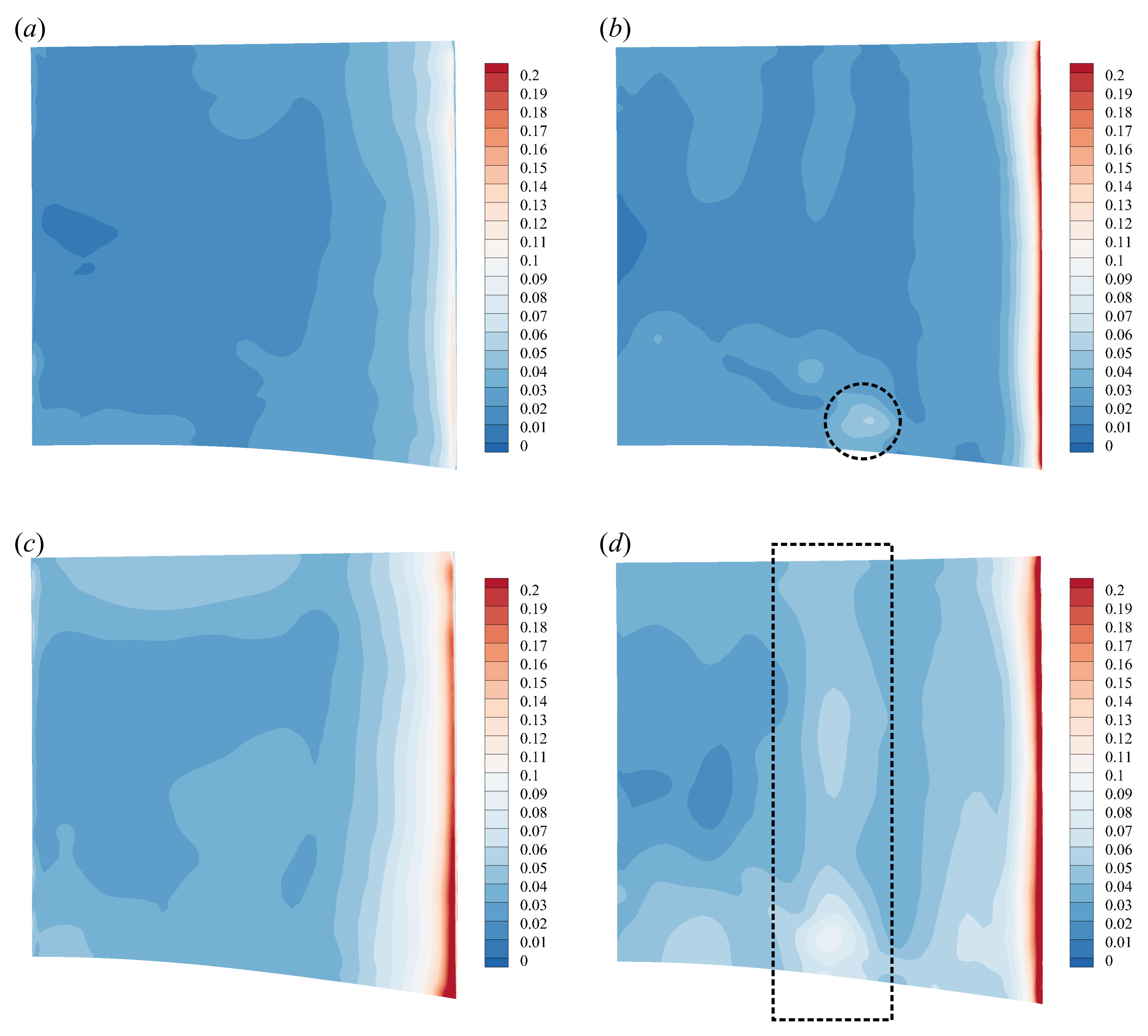
Figure 22 and
Figure 23 show the distributions of the pressure fluctuation amplitude on the rotor and the stator, respectively, at the two gaps with
. The amplitudes were quantified by half the peak-to-peak values for the unsteady pressures on the blade segments. Specifically, the rear part of the rotor blade suffered more from the fluctuation when the gap was reduced and the highest value was observed near the trailing edge. This fluctuation included the unsteady pressure generating on the stator and propagating upstream, and reduction of the gap not only strengthened the fluctuation on the stator, but also shortened the distance of attenuation, thus, highly increasing the amplitude of the unsteady pressure on the rotor blade. Przytarski and Wheeler [
17] reported that the freestream turbulence levels rose significantly after the gap was reduced, which might also be related to the stronger fluctuation propagating upstream.
On the other hand, the aeroacoustic performance of the compressor depends on the flow characteristics of the stator. At the designed gap, only the leading-edge region of the stator exhibited pretty violent pressure fluctuation while the fluctuation was not obvious in most of the remaining regions, as shown by
Figure 23a,b. After the gap was reduced, the fluctuation amplitudes were also found to increase on the whole stator, like the rotor. Specifically, the highest amplitude on the leading edge of the stator’s pressure side was more than twice the corresponding value at the designed gap, as can be identified from
Figure 23a,c. The region with the highest fluctuation amplitude on the stator’s suction, i.e., the red areas at the leading edge in
Figure 23b,d, was also found to expand toward the rear of the blade after the gap reduced. With the rotor passing, the leading edge of the stator chopped the rotor wake into two parts, resulting in violent fluctuation at this region, which also formed the main source of interaction noise.
In addition, at the designed gap, higher pressure fluctuation also existed near the mid-chord of the suction surface of the stator, as marked by the black dashed circle in
Figure 23b. When the gap reduced, this region enlarged along the span as marked by the black dashed box in
Figure 23d. This region with stronger fluctuation was well related to the interaction of the rotor wake and the stator flow. As can be found from the contours of Mach number in
Figure 16, there was a region of flow acceleration near the leading edge of the suction surface of the stator, the end of which is marked by a dashed line in black. After the rotor wake was chopped by the stator, a new wake formed and evolved along the suction surface of the stator. Due to the interaction of the rotor wake and the stator flow, stronger pressure fluctuation then formed near the end of the acceleration region as a consequence, as revealed by
Figure 23b,d. There was another small acceleration region downstream of that marked in
Figure 16d on the suction surface of the stator and obvious pressure fluctuation could also be observed near it, as shown by
Figure 23d. Therefore, in addition to the chop of rotor wake, the interaction of the rotor wake/stator flow was another main source of pressure fluctuation on the stator, and both of the two sources could be strongly enhanced by the reduction of the gap.


