Article

Turbomachine Operation with Magnetic Bearings in Supercritical Carbon Dioxide Environment

by
Alexander Johannes Hacks
* and
Dieter Brillert
Chair of Turbomachinery, University of Duisburg-Essen, Lotharstraße 1, 47057 Duisburg, Germany
*
Author to whom correspondence should be addressed.
Int. J. Turbomach. Propuls. Power 2022, 7(2), 18; https://doi.org/10.3390/ijtpp7020018
Submission received: 2 December 2021 / Revised: 20 May 2022 / Accepted: 8 June 2022 / Published: 14 June 2022
(This article belongs to the Special Issue Advances in Critical Aspects of Turbomachinery Components and Systems)

Abstract

:
In the sCO2-HeRo project, the Chair of Turbomachinery at the University of Duisburg-Essen developed, built and tested a turbomachine with an integral design in which the compressor, generator and turbine are housed in a single hermetic casing. However, ball bearings limited operation because their lubricants were incompatible with supercritical CO2 (sCO2) and they had to operate in gaseous CO2 instead. To overcome this problem, the turbomachine was redesigned built and tested in the sCO2-4-NPP project. Instead of ball bearings, magnetic bearings are now used to operate the turbomachine with the entire rotor in sCO2. This paper presents the revised design, focusing on the usage of magnetic bearings. It also investigates whether the sCO2 limits the operating range. Test runs show that increasing the density and rotational speed results in greater deflection of the rotor and greater forces on the bearings. Measurements are also analyzed with respect to influence of the density increase on the destabilizing forces in the rotor–stator cavities. The conclusion is that for the operation of the turbomachine, the control parameters of the magnetic bearings must be adjusted not only to the rotor speed, but also to the fluid density. This enabled successful operation of the turbomachine, which reached a speed of about 40,000 rpm during initial tests in CO2.

1. Introduction

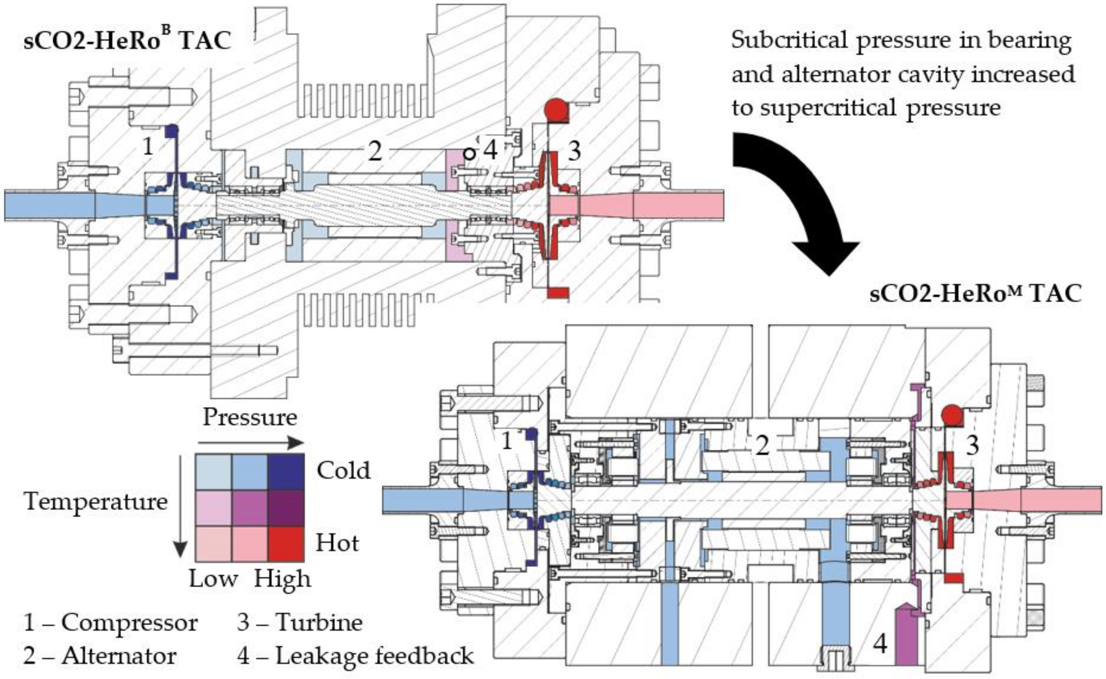
This research paper focuses on the work conducted by the Chair of Turbomachinery at University Duisburg-Essen in the sCO2-4-NPP project to develop and test a compact turbomachine with integral design and active magnetic bearings (AMB) in CO2 in the supercritical state (sCO2). It is part of a novel heat removal system for residual decay heat in nuclear power plants developed in the previous project sCO2-HeRo (Benra et al. [1] and Starflinger et al. [2]). The application requires the overall system and the turbomachine to be compact, robust and simple. Therefore, the original turbomachine, called sCO2-HeRoB TAC, presented by Hacks et al. [3] consists of a one-stage compressor and turbine on either end of a shaft with an alternator in the middle. While the TAC meets the requirements of compactness and simplicity due to all components being housed in a single hermetic casing, it has hybrid angular ball bearings lubricated with grease to support the rotor. Unfortunately, the grease proved to be incompatible with sCO2. As a result, an additional auxiliary pump had to be applied to reduce the pressure of the CO2 at the bearings and run them in gaseous CO2 instead. This made the system less compact and harder to control because the outlet pressure of the auxiliary pump and compressor had to be balanced against each other. Furthermore, a safety relief valve ensured subcritical pressure at the bearings. Therefore, a failure of the pump results in loss of CO2 inventory and renders the heat removal system less robust. To overcome this drawback of the original design, the new TAC needs to operate with all rotor–stator cavities filled by sCO2 as indicated by the darker blue and purple colors in Figure 1. AMBs do not require lubricants. Therefore, they represent a suitable technology to replace the ball bearings in the original design and eliminate the additional auxiliary pump in the system.
However, there is scarce research documented in the literature concerning the operation of turbomachines for sCO2 with AMB. To the author’s knowledge, only a collaboration between the Korea Atomic Energy Research Institute (KAERI, Daejeon, Korea) and the Korea Advanced Institute of Science and Technology (KAIST, Daejeon, Korea) has published experiments on AMB operating in sCO2. They aim to operate a hermetic compressor with high-pressure sCO2 at the bearings, similar to the TAC described by the authors for the sCO2-HeRo system. In 2016, Cha et al. [4] reported sCO2 fluid properties to cause instability of the bearing rotor leading to the erection of AMB test rig. In 2019, Kim et al. [5] published first results. Based on their experiments, they show that sCO2 indeed has the potential to affect the rotor due to high density and sensitivity of density to pressure [6]. Consequently, they are working on a model to predict the effect of sCO2 in the turbomachinery cavities on the rotor and to find a suitable control strategy for the AMBs [6,7].
This paper describes the design and operation of the newly built TAC with AMB (called sCO2-HeRoM TAC). The key features and dimensions are highlighted in this paper. Similar to previous studies at KAERI and KAIST, a theoretic analysis is performed, showing potential of sCO2 in the alternator cavity to cause the largest destabilizing forces, compared to the other cavities. Consequently, a cooling concept was developed to reduce the density of sCO2 within the rotor–stator cavity and the resulting destabilizing forces. During the initial test runs in the sCO2-HeRo cycle, the density of CO2 gradually increased. Measurements are presented for increasing the speed at different density levels. Based on this, additional measurements at constant rotational speed are employed to evaluate the potential of sCO2 density to destabilize the rotor. During this process, the sCO2-HeRoM TAC reached the design rotational speed of 50,000 rpm in air and approximately 30,000 rpm at compressor inlet density of almost 650 kg/m3. Furthermore, observations of adapting control parameters of the AMB system to the sCO2 fluid density are presented. Overall, operability of sCO2-HeRoM TAC is demonstrated.

2. Design of the sCO2-HeRoM Turbomachine with Active Magnetic Bearings

The design of the sCO2-HeRoM TAC is based on the sCO2-HeRoB TAC. Hacks et al. [3] describe the design of the latter in detail and show main cycle parameters. The compressor geometry [3,8] as well as performance measurements [9,10] are public, too. Figure 1 shows the overall layout of the TACs. It is identical for both the sCO2-HeRoM TAC and the sCO2-HeRoB TAC bearing a turbine, alternator and compressor on a single shaft in a hermetic casing. Design features such as the compressor and turbine geometry are identical, too. The major difference is the type of bearing. In the sCO2-HeRoM TAC, the original ball bearings were replaced by AMB to eliminate the limitations imposed by the grease. The latter was found to dissolve in sCO2 and was therefore maintained in gaseous CO2 in the sCO2-HeRoB TAC by reducing CO2 pressure to subcritical pressure, indicated by lighter blue color in Figure 1, with an additional pump. AMB do not require a lubricant and therefore overcome the restrictions imposed by gaseous CO2 at the bearings. However, they have certain characteristics, which must be considered for design and operation. In general, AMB systems require two radial bearings and a separate axial thrust bearing, which is different from the hybrid angular ball bearings originally used. Previously, only a single radial and one combined axial–radial bearing were required because this bearing type can support both axial and radial forces [3]. Furthermore, AMB requires sensors to control the position of the levitated rotor and additional safety bearings to keep the rotor from crashing into the stator in case of AMB failure or overload. This has several implications for the new TAC. First, the rotor is about 20% longer due to the additional axial bearing, sensors and safety bearings. Therefore, the shaft must have a larger diameter to keep the critical speed above the design speed. Second, the thrust disk of the axial bearing adds significantly to the already high windage losses. These are larger in the sCO2-HeRoM TAC compared to the sCO2-HeRoB TAC due to the larger shaft diameter in general, the new thrust disk and because sCO2 is denser than gaseous CO2. In addition, uneven pressure distribution on both sides of the thrust disk may result in high axial thrust. Third, the labyrinth seal clearance is kept at 0.1 mm because of the small design mass flow rate of the cycle of only 0.65 kg/s. Therefore, maximum deflection of the rotor must remain below 0.1 mm at the seals and is only 0.08 mm at the safety bearings. This requires precise manufacturing and assembly. It also limits the maximum radial deflection of the rotor during operation.

2.1. Design of Internal Flow Paths

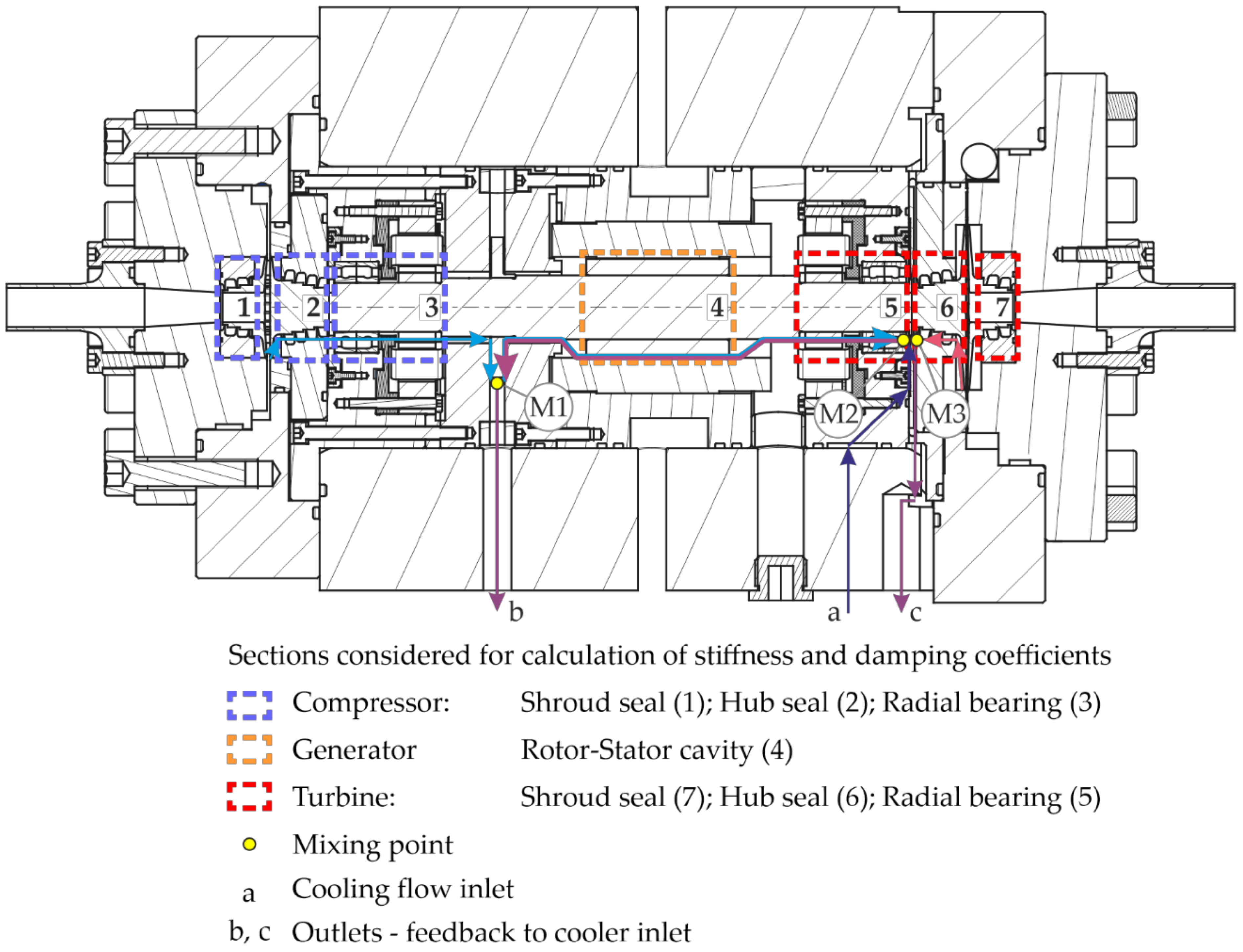
Further requirements relate to the design of flow paths within the TAC. The AMB and sensors are electronic components that need to stay below their temperature limit of about 150 °C. However, CO2 temperatures at the turbine measure up to 200 °C which is above the limit and requires cooling by cold CO2. Furthermore, the sCO2 properties inside the TAC affect the rotor and components such as the bearings and alternator and require interactive design of the rotor, sCO2 flow paths and AMB controller parameters. On one hand, the sCO2 needs to provide cooling to the alternator and AMB, which requires high heat capacity and consequently high density of the sCO2. On the other hand, high density means a stronger interaction between the rotor and surrounding sCO2, which translates into higher windage losses and higher pressure gradients inside rotor–stator cavities causing larger forces on the rotor. At the thrust disk and impellers, the pressure gradients may cause significant axial thrust, which must be covered by the load capacity of the axial thrust bearing. Pressure gradients in the radial direction cause forces that must be supported by journal bearings. If these are too large, the deflection of the rotor increases until the rotor touches the safety bearings causing the TAC to shut down. To meet the contradictive demand of high vs. low density inside the rotor–stator cavities, an additional sCO2 inlet and outlets were implemented in the central part of the TAC to control CO2 flow rate, direction and density. The positions of the additional inlet and outlets are marked in the cross-section in Figure 2 and the simplified scheme in Figure 3 shows two resulting configurations for the internal flow paths. Configuration 1 uses the leakage outlet (c) and is similar to the original design, depicted in Figure 1. It has the advantage of requiring no additional cooling flow through (a). However, cold sCO2 from compressor leakage with high-density flows along large portions of the rotor, around the axial thrust disk and through the generator cavity before it is mixed with hot turbine leakage in mixing point M3. This translates to high windage losses, large axial thrust and high radial forces in the generator cavity. In configuration 2, the leakage is extracted at the thrust disk (b) of the axial bearing. It is a mixture of the compressor leakage and the cooling flow through the generator, mixed in point M1. The cooling flow (a) is mixed with hot turbine leakage between turbine hub seal (6) and radial bearing (5) in mixing point M2. Thus, density of sCO2 flowing through the generator cavity (4) is lower and controllable by cooling flow (a). This means lower windage losses, radial fluid forces and axial thrust.

2.2. Fluid Forces of sCO2 in Rotor–Stator Cavities of the sCO2-HeRoM Turbomachine

As this paper relates to the AMB used in sCO2-HeRoM TAC, windage losses, axial thrust and the cooling effect of sCO2 calculated with in-house code are not discussed in detail. The focus lies on the radial deflection of the rotor and radial forces in the bearings. These are caused by forces on the rotor due to imbalance and rotationally asymmetric pressure fields around the rotor. The latter occurs in the impellers and in the rotor–stator cavities. The rotor–stator cavities are the labyrinth seals and cavities in the manner of cylindrical shells such as the journal bearings (safety bearings, sensor rings, radial bearings) and the generator cavity. In the radial bearing, the space between the electromagnets is closed similar to the journal bearing shown by Jin et al. [7] to obtain a nearly cylindrical surface and avoid large forces caused by irregular geometry reported by Kim et al. [5]. To account for the forces (F) in the rotordynamics analysis, equivalent stiffness (K) and damping coefficients (C) are used together with deflection x and y (see Equation (1)). These are calculated using the commercially available tool xLRotor [11] for different sections indicated in Figure 2. For labyrinth seals, a model designed for a compressible gas seal was used, while the other cavities were approximated as annular seals. Calculations of stiffness and damping coefficients were performed for sections in Figure 2 considering the pressure and density distribution along the flow path of sCO2 inside the TAC. However, a constant average density and viscosity was used as input for the annular seal model and the compressible gas seal model used a constant compressibility factor to account for fluid properties. Due to the small change of fluid properties within the annular cavities and relatively little pressure difference across the seals, the deviations caused by the inaccuracy of fluid properties are considered to be limited. They reveal that all cavities considered have a destabilizing effect, i.e., the forces of the fluid act on the rotor in a direction that increases the deflection of the rotor. Considering flow path configuration 1, Figure 4 shows the results of an example calculation. Coefficients of the different sections in Figure 2 are displayed as a fraction of those in the generator cavity (4). Note that sections (3) and (5) are divided into the different elements of the radial bearing, safety bearing, sensor ring and the radial bearing itself. According to Figure 4, the generator cavity (4) dominates the rotordynamic influence of the sCO2 compared to the other cavities. Coefficients are at least six-times larger for cross-coupled stiffness K x y = K y x and direct damping C x x = C y y and almost 10-times higher for direct stiffness K x x = K y y and cross-coupled damping C x y = C y x . The reason for the dominance of the generator cavity is the size of the cavity, which has twice the diameter and more than twice the length of the cavity in safety bearings. The latter has high coefficients because of a narrow radial gap width of only 0.08 mm. In addition, the liquid-like sCO2 causes larger coefficients for seals and bearings on the compressor side, even though those on the turbine side bear the same geometry. Since Figure 4 suggests that forces originating in the generator cavity are dominant over those in other cavities, particular attention is paid to the effect of density alterations inside this cavity on radial deflection and bearing forces.
F x F y = K x x K x y K y x K y y x y C x x C x y C y x C y y x ˙ y ˙
Figure 5 shows a sensitivity study of radial clearance, density inside the generator cavity and rotational speed on the stiffness and damping coefficients. In the study, only one parameter is changed while the others remain constant. To increase radial clearance, the rotor diameter is reduced. Density is changed at constant pressure. The study is carried out with xLRotor [11] using a model for a short annular seal. Although the cavity fails to meet the requirements of a short seal, relationships in terms of the studied parameters are considered equal for long- and short-seal models. Figure 5 presents clearance height as having a significantly larger effect on the cross-coupled stiffness (and direct damping) than on direct stiffness. On the other hand, decrease in density and rotational speed lead to a larger reduction of direct stiffness coefficients. In terms of forces, this means density and rotational speed have more influence on forces pointing towards (stabilizing) or away from the center of rotation (destabilizing). For sCO2-HeRoM TAC, the focus lies on these forces and consequently the direct stiffness coefficients. The reason is that in the (original) flow path configuration 1 (see Figure 3) the direct stiffness coefficients were too large for operation of the sCO2-HeRoM TAC. Therefore, flow path configuration 2 was established to reduce the density in the generator cavity and to allow operation of the sCO2-HeRoM TAC. This and the general influence of density suggested by Figure 5 means that it must be controlled during operation.

3. Operation of the sCO2-HeRoM Turbomachine

The goal of the initial operation of the sCO2-HeRoM TAC is to prove its operability in the sCO2-HeRo cycle. It also aims to verify the concept of internal flow paths and improve understanding of the effects of rotational speed and density on the operation of the TAC in sCO2. Based on findings of the previous chapter and the publications of Cha et al. [4] and Kim et al. [5], operation of a TAC with AMB becomes more difficult as density increases. Therefore, the tests start with operation in air at atmospheric pressure, considered as known conditions. Then, they proceed with CO2 in gaseous conditions and low density. As shown in Figure 6, the density at the compressor inlet, representing the highest density in the cycle, increased gradually starting from the gaseous state of CO2 at 160 kg/m3 in region I until reaching supercritical conditions for the first time in region III with a density above 300 kg/m3. Finally, region V reached design density and design static inlet pressure of 566 kg/m3 and 78.3 bar at the compressor inlet, respectively. Together with regions III, IV and VI, the tests covered the whole range of possible compressor inlet conditions. This includes higher static inlet pressures of up to 90 bar, maximum inlet density of 650 kg/m3 and conditions around the critical point. During operation of the TAC in the different regions of compressor inlet conditions in Figure 6, the deflection of the rotor and the radial, magnetic forces calculated for the bearings were monitored. Radial deflections are measured at the radial bearings with eddy current sensors monitoring the position of the rotor relative to the stator. At each bearing, four sensor pairs opposite to each other are employed. The increase of rotational speed in different regions of compressor inlet conditions is presented first. Afterwards, measurements at constant rotational speed are discussed with respect to the influence of density. Measurements are compared to obtain a qualitative understanding regarding the dependence of deflection and bearing forces on rotational speed and sCO2 density.

3.1. Increasing Rotational Speed

Here, a comparison between test runs in different regions of Figure 6 is presented. Each test run also shows the effect of rotational speed on the radial deflection of the rotor and the radial forces in the bearings. From Figure 5, the observation of an increase in force and/or deflection when increasing both rotational speed and density is expected. Whereby rotational speed is expected to demonstrate a larger effect. The analysis starts with a preliminary test conducted in air. The TAC reached a design rotational speed of 50,000 rpm as shown in Figure 7. For readability, the (thousands) of measurement points are not depicted. Instead, the shaded areas represent the area where 90% of the measurement points are located. That means that for each rotational speed, the lower and upper bound of the shaded area are chosen in a way that 90% of measurements at the respective rotational speed are included. During air pre-tests, a basic AMB controller was used without considering rotordynamic coefficients of seals and cavities. Since air density represents only 1% of the density in region I of operation in CO2 (see Figure 7) and even less, only 0.3%, of the compressor design inlet density, forces due to fluid inside the impellers and cavities are considered negligible compared to operation in CO2. Figure 7 shows deflection of rotor at standstill to be on average 3 μm for the compressor bearing and 2 μm for the turbine bearing and to fluctuate in the same range. As speed increases, both deflection and forces increase slightly. At 50,000 rpm, the maximum deflection reached approximately 12 μm or 15% of the maximum clearance in the safety bearings. Forces remained well below 10% of the maximum bearing force.
In general, the preliminary air test reached 50,000 rpm and showed the rotor to be well-balanced and clearances to be as designed. It proved general operability of the TAC and provided the basis for further testing in CO2.
The next step included the first tests regions I–III in Figure 6, where CO2 was in a gaseous or gas-like state. From regions I–III, the density increases at the compressor inlet and in the whole cycle. Furthermore, the density difference between the turbine inlet and compressor inlet is small because the maximum temperature of CO2 is kept well below 60 °C. Finally, the maximum speed during these tests is limited to 40,000 rpm because, unlike tests in air, the TAC relies on turbine power to reach maximum speed owing to the higher density at the compressor requiring more power. Due to low compressor inlet density and low turbine inlet temperature, this power cannot be provided.
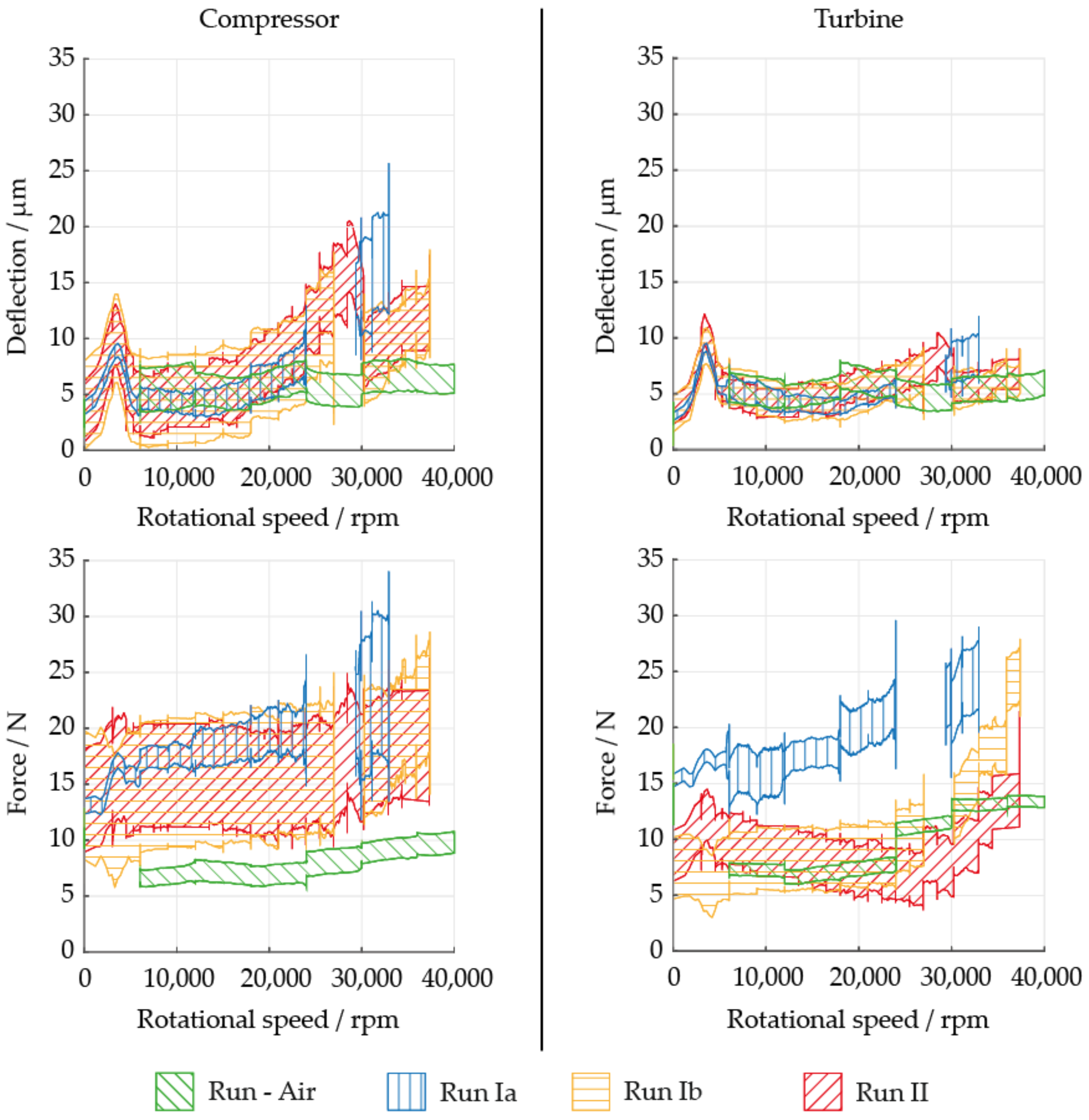
Figure 8 presents a comparison of measurements for three test runs and the test run in air. Test run Ia and Ib are at the density in region I and run II is in region II. During run Ia, the initial controller design used for the air test was not modified. As in the air test, increased deflections and forces were observed as rotational speed increased. Moreover, the fluctuations in measurements (depicted as larger enclosed area) now seem to also increase. Above 20,000 rpm, the deflections are larger than for the test run with air, especially on the compressor side. Figure 8 shows large deflections of about 25 μm or 31% of the clearance at the compressor bearing at a speed of 33,000 rpm or 66% of design rotational speed. This is already more than twice the deflection found in the air test at design rotational speed. Note the peak at approximately 5000 rpm, which indicates switching on the imbalance controller. It is active for larger rotational speeds and strongly reduces the deflection of the rotor. Similar action is taken again during test runs Ib and II. The controller parameters are changed so that the deflection of the rotor is reduced at speeds above 27,000 rpm. Therefore, there is drastically less deflection of the rotor for rotational speeds above 27,000 rpm compared to run Ia. For approximately 38,000 rpm, values are now 40–50% larger than values at design speed in the test run with air. Observing the radial force in both bearings, the forces in the compressor bearing are larger than for the air case. On the other hand, forces in the turbine bearing remain similar but for larger fluctuations (larger enclosed area). Run Ia is an exception, exhibiting a much larger force. It is interesting to note that changing the control parameters when exceeding 27,000 rpm leads to a steeper increase in the forces as a function of speed.
These observations suggest that conditions in CO2 indeed have an effect on operating the TAC with AMB. The reason for the observed behavior is likely due to the approximately 100-fold higher density. Furthermore, a change in control parameters is required to balance the effect of CO2 on the rotor.
The next step is test run III, where CO2 is in supercritical, gas-like conditions in region III right of the pseudocritical line (see Figure 6). The density is now 150–200% of the density of run II, which was performed with a compressor inlet density of about 200 kg/m3. Approaching 20,000 rpm, the deflection at both the turbine bearing and compressor increases more than previously observed (see Figure 9). Therefore, the rotational speed for adjusting control parameters to limit deflections is reduced from 27,000 rpm to just above 18,000 rpm. This results in deflections at speeds greater than 18,000 rpm being in the same range as the previous test runs in CO2. A change in forces similar to before is observed. However, the size of the enclosed area representing the scatter of radial forces of the bearings increases rather than the mean value. The fluctuations are approximately twice as large as previously measured. Again, it is assumed that this is related to the increasing interaction of CO2 with the rotor due to greater density.
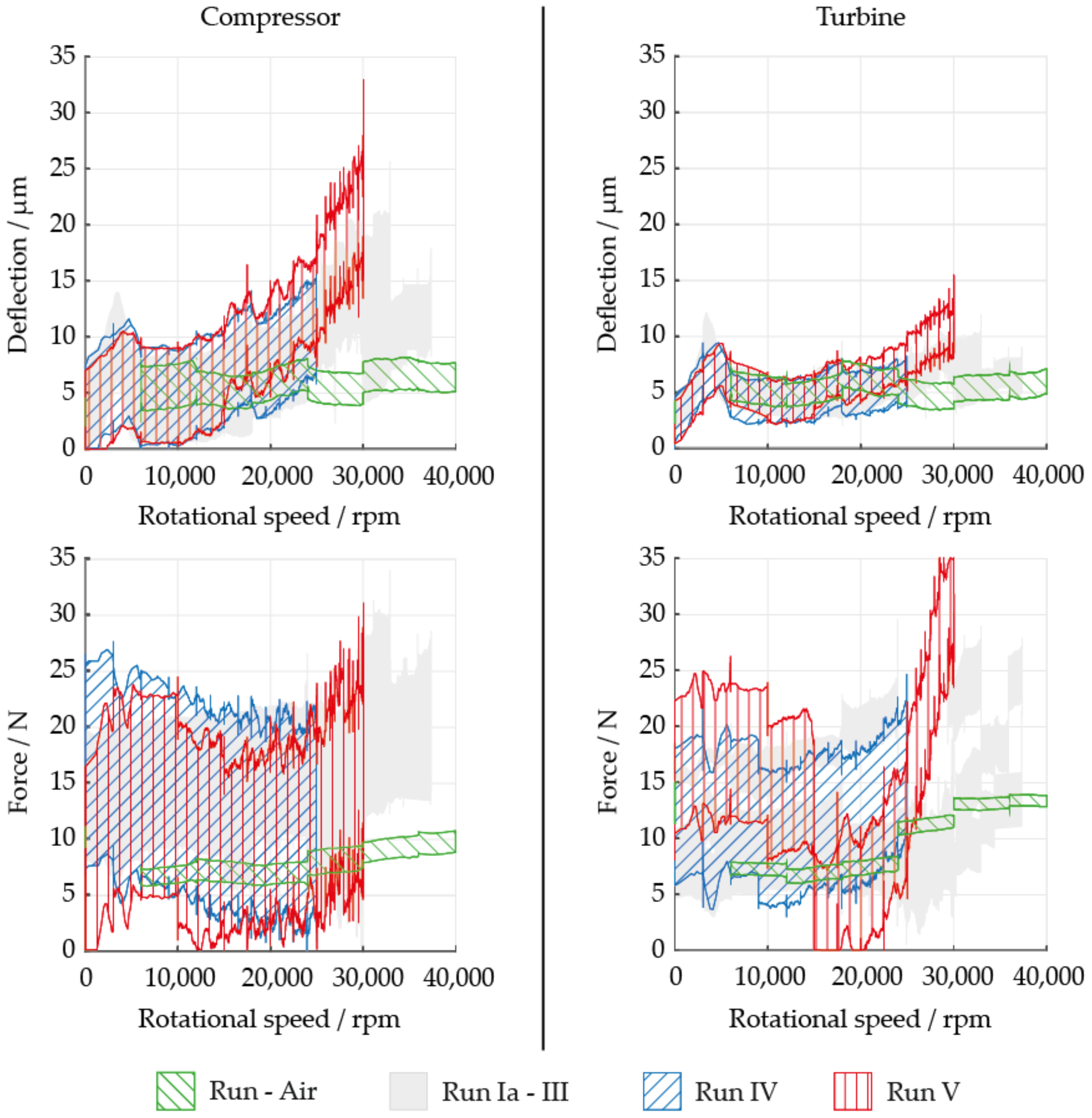
Finally, compressor inlet conditions for test run IV and V are brought to liquid-like sCO2 conditions left of the pseudocritical line in regions III, IV and V. The test runs featured compressor inlet densities of about 450 kg/m3 and 600 kg/m3, respectively. Note that the density at the turbine inlet remains similar to test run III due to the elevated inlet temperature. As in the previous run, the maximum deflection increases mainly at the compressor bearing (see Figure 10). The maximum deflection reaches 40% of the clearance height at approximately 30,000 rpm (60% of design speed). While maximum force in Figure 10 and its fluctuation at the compressor are similar to previous tests, the scatter of measured values for deflection increases. For the turbine bearing, a reduction in force can be seen at 15,000 rpm when the turbine bypass valve that was previously completely open is closed to 30%. At 25,000 rpm, it is closed to 10%, resulting in an increase in force at the turbine bearing. Additionally, the force increases more rapidly as rotational speed rises. Between 11% and 30% opening of the turbine bypass marks the point at which the flow direction changes at the turbine. While the turbine impeller “pumps” sCO2 due to e.g., friction at the disk when the pressure ratio across the turbine is low due to the open bypass valve, closing the valve means the pumping effect can no longer overcome the rising pressure ratio. Thus, a “wrong” flow direction at the turbine results in a larger force on the turbine bearing. In addition, deflections up to 15,000 rpm are in a similar range to the air tests, but become much larger at speeds near 30,000 rpm. Therefore, future test runs require further modification of the control parameters to achieve speeds above 30,000 rpm when the compressor is operated with high-density liquid-like CO2.
The speed up tests showed that at low rotational speeds of up to 15,000 rpm, deflection is similar to the test run in air, regardless of density. It appears that the AMB is able to compensate the influence of sCO2, even though larger forces are required. At larger rotational speeds, radial deflections and forces remain almost constant in test run with air, while the values and scatter of the measurements increase significantly for test runs in CO2. The difference becomes larger when the density at the compressor inlet increases. As shown, a change of AMB control parameters can reduce deflections at the cost of larger forces. Therefore, AMBs are able to actively compensate the effect of sCO2 on the rotor in the speed and density range investigated.

3.2. Increasing Density

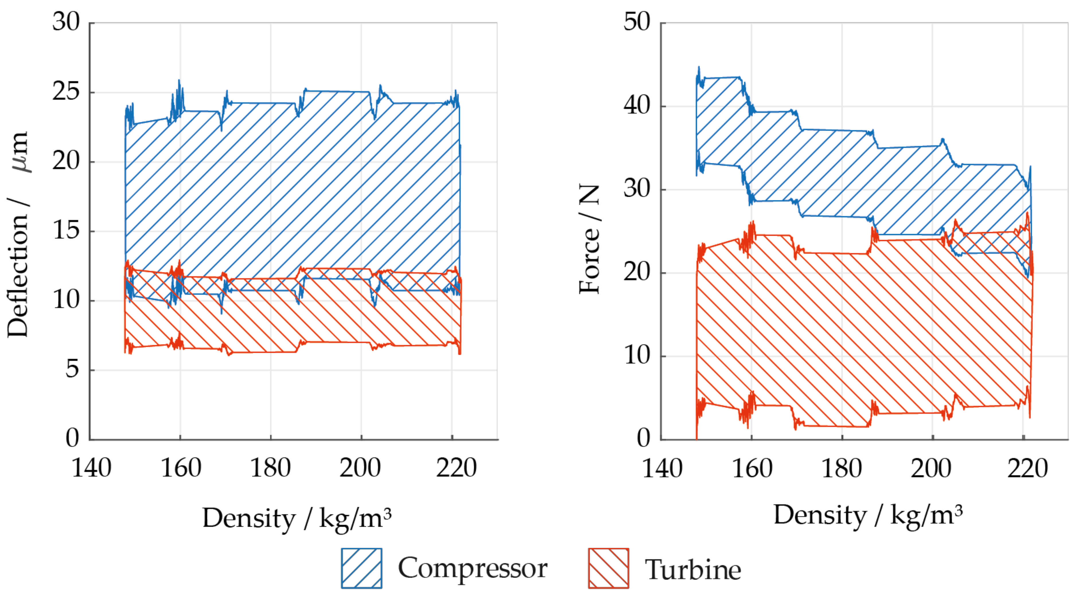
The previous section clearly shows that the radial deflection of the rotor and the radial forces in the bearings increase with speed. It also shows an increase in deflection and bearing forces for test runs in regions with higher compressor inlet density. A similar result is presented by Kim et al. [6], who describe the effect of different sCO2 conditions on radial force on the rotor for a cylindrical shell-type rotor–stator cavity. They show that an increase in density can also increase forces of sCO2 on the rotor. To investigate the effect more closely, measurements at a constant rational speed are presented. Figure 11 shows that an increase in compressor inlet density indeed increases radial deflection of the rotor and radial forces inside the bearings. However, it should be noted that the increase of compressor inlet density has several effects. For example, it leads to an increase in the pressure ratio and thus in the force acting on the blades of the impeller.
To separate the different effects of increases in density, the pressure ratio is more closely examined. The pressure ratio can usually be changed by altering the flow rate of the compressor. The sCO2-HeRo cycle features a compressor bypass valve for this purpose. However, the change in pressure ratio due to closure of the bypass valve is small and no effect on deflection or radial bearing forces was observed. This is due to flat curves of constant speed in the compressor performance map (compare Hacks et al. [3]). However, the pressure rise in the compressor is strongly dependent on its inlet density (compare Hacks et al. [9,10]). In the case of Figure 11, it doubles as inlet density increases from 325 kg/m³ to 580 kg/m³. Therefore, it can be concluded that a change of flow rate at the compressor inlet is not responsible for the increase in bearing forces and radial deflection of the rotor but the direct effect of density on pressure rise might be.
Second, the effect of density inside the rotor–stator cavities is analyzed. As Figure 5 indicates, fluid forces inside rotor–stator cavities increase with local density, which was also reported by Kim et al. [6]. Here, only the effect of changing the density in the generator cavity is considered, because design calculations indicated the largest destabilizing forces to be caused by CO2 inside the cavity (see Figure 4). Figure 12 presents the radial deflection of the rotor and radial bearing forces for one set of measurements when the valve controlling the cooling flow rate (a) was throttled. The further this valve is throttled, the lower the density inside the generator cavity becomes. The expectation is that lower density reduces the deflection of the rotor and radial force in the AMB due to smaller destabilizing forces. However, Figure 12 shows no considerable change of deflection and larger forces for smaller density inside the cavity (contrary to expectations). The behavior was also checked for other series of measurements. While the change in radial force is often less pronounced than in Figure 12, no definite increase in deflection or radial force is observed with density. The reason behind this is uncertain, but might be related to one of the following reasons. Leakage flow over the hub seal of the turbine impeller mixes with the cooling flow rate (a) inside the TAC (see Figure 3). Neither of the two mass flows can be measured directly, but must be calculated. Since the mixing with the leakage flow occurs inside the TAC, only the density inside the cavity is calculated and thus subject to uncertainties in calculating mass flow over the seal and valve. Another reason could be that according to the model used for Figure 5, the direct stiffness coefficient has a quadratic dependency on rotational speed. Therefore, radial forces in the cavity might only be significant at higher rotational speeds.
Finally, it was discovered that an increase in density at the compressor inlet does not lead to an increase in density in the generator cavity, even though the cooling flow rate rises and the temperature drops. Instead, the density remains almost constant because the pressure inside the cavity decreases. This also hints that forces acting on the compressor impeller dominate the fluid forces that originated in the generator cavity. Therefore, the effects on the compressor impeller dominate the increase in radial deflection of the rotor and the increase in radial bearing forces, at least in the speed and density range studied.

4. Summary and Conclusions

The paper first presents the design of the sCO2-HeRoM TAC. Its shaft is supported by AMBs so that the CO2 can remain in a supercritical state throughout the TAC, shaking off the shackles of the previously used grease lubrication, which requires gaseous CO2. To integrate the AMBs into the TAC, the cooling concept was revised to ensure cooling of the AMB on the turbine side and reduce windage losses, axial thrust and destabilizing forces. It is shown that the latter can be expressed by stiffness and damping coefficients and the coefficients of the generator cavity are expected to be dominant. They increase with rising rotational speed and density and decrease with larger clearance height. Furthermore, it is demonstrated that objectives of cooling on one hand and reducing windage losses and fluid forces on the other hand are contradictory since one requires cold and the other warm CO2 with high and low density, respectively. The new cooling concept allows for a compromise, as regulation of the cooling flow regulates the temperatures and densities inside the TAC. Moreover, the density in the generator cavity can be kept constant even if the density increases at the compressor inlet. Therefore, cooling concept 2 is suitable for sCO2-HeRoM TAC with AMBs. Finally, the first test runs with the sCO2-HeRoM TAC were successfully completed. By adjusting the controller parameters to match the fluid properties, stable operation of the TAC was achieved at 30,000 rpm for a compressor inlet density as high as 650 kg/m3. The conclusion is that a TAC using AMBs can be operated in sCO2 if the forces related to the high density are considered.
Furthermore, measurements of radial deflection of the rotor and radial forces in the AMBs during several test runs are presented. In an initial step, the sCO2-HeRoM TAC reached design rotational speed of 50,000 rpm in air, proving operability with negligible fluid-induced forces. Increasing compressor inlet density and rotational speed demonstrated an expected increase in radial deflection of the rotor and radial forces in the bearings with both increasing density and rotational speed. Furthermore, it was shown that adjusting controller parameters bears the ability to reduce deflection of the rotor by applying larger forces in the AMBs to balance fluid-induced forces.
Moreover, density increase is also analyzed at constant rotational speed. An increase of density at the compressor inlet is associated with an increase in radial deflection of the rotor and larger radial forces. The density on the turbine side and inside the generator cavity remains approximately constant for the related measurements. However, pressure rise increases strongly with compressor inlet density. In another attempt to demonstrate the impact of density on destabilizing forces inside rotor–stator cavities of the cylindrical-shell type, the density inside the generator cavity was changed while other properties were kept approximately constant. Contrary to expectations, no significant change in radial deflection was observed. Radial forces even tended to decrease. It appears that, at least at for the rotational speed studied, the force inside the generator cavity does not dominate the overall radial forces on the rotor. This may be related to a quadratic dependency of the direct stiffness coefficient on rotational speed indicated by the model used. Therefore, the relationship between the fluid forces that originated in the cavity and the total radial force on the rotor could increase and become dominant at higher rotational speeds. However, for the speed and density range studied, other radial forces acting on the compressor impeller or in the cavities on the compressor side seem to dominate the fluid forces on the rotor and need to be considered in future studies. A detailed experimental analysis of the different components of the destabilizing force on the rotor requires a rotor geometry with reduced complexity.

Author Contributions

Conceptualization, A.J.H.; methodology, A.J.H.; validation, A.J.H.; formal analysis, A.J.H.; investigation, A.J.H.; data curation, A.J.H.; writing—original draft preparation, A.J.H.; writing—review and editing, A.J.H. and D.B.; visualization, A.J.H. and D.B.; supervision, D.B.; project administration, D.B.; funding acquisition, D.B. All authors have read and agreed to the published version of the manuscript.

Funding

This project has received funding from the Euratom research and training programme 2014–2018 under grant agreement No. 847606. Ijtpp 07 00018 i001

Data Availability Statement

Data available on request. The data presented in this study are available on request from the corresponding author.

Conflicts of Interest

The authors declare no conflict of interest.

References

  1. Benra, F.-K.; Brillert, D.; Frybort, O.; Hajek, P.; Rhode, M.; Schuster, S.; Seewald, M.; Starflinger, J. A supercritical CO2 low temperature Brayton-cycle for residual heat removal. In Proceedings of the 5th International Symposium—Supercritical CO2 Power Cycles, San Antonio, TX, USA, 29–31 March 2016. [Google Scholar]
  2. Starflinger, J.; Brillert, D.; Frybort, O.; Hájek, P.; Hennink, A.; Freutel, T. Raising nuclear reactor safety to a higher level—The supercritical CO2 heat removal system—sCO2-HeRo. In Proceedings of the 26th International Conference Nuclear Energy for New Europe NENE, Bled, Slovenia, 11–14 September 2017. [Google Scholar]
  3. Hacks, A.; Schuster, S.; Dohmen, H.J.; Benra, F.-K.; Brillert, D. Turbomachine Design for Supercritical Carbon Dioxide within the sCO2-HeRo.eu Project. J. Eng. Gas Turbines Power 2018, 140, 121017. [Google Scholar] [CrossRef] [Green Version]
  4. Cha, J.E.; Cho, S.K.; Lee, J.I. Operation Test of the Supercritical CO2 Compressor Supported with Active Magnetic Bearing. In Proceedings of the Transactions of the Korean Nuclear Society Autumn Meeting, Gyeongju, Korea, 27–28 October 2016. [Google Scholar]
  5. Kim, D.; Baik, S.; Lee, J.I. Investigation of Magnetic Journal Bearing Instability Issues in Supercritical CO2 Turbomachinery. In Proceedings of the ASME-JSME-KSME 2019 8th Joint Fluids Engineering Conference, San Francisco, CA, USA, 28 July–1 August 2019. [Google Scholar] [CrossRef]
  6. Kim, D.; Baik, S.; Lee, J. Instability Study of Magnetic Journal Bearing under S-CO2 Condition. Appl. Sci. 2021, 11, 3491. [Google Scholar] [CrossRef]
  7. Jin, S.-H.; Cha, J.-E.; Chang, J.-U.; Choi, S.-H.; Ahn, H.-J. Controlling the Fluid Induced Instability of a Supercritical CO2 Compressor Supported by Magnetic Bearing. KSPE 2020, 37, 737–742. [Google Scholar] [CrossRef]
  8. Hacks, A.J.; Abd El Hussein, I.; Ren, H.; Schuster, S.; Brillert, D. Experimental Data of Supercritical Carbon Dioxide (sCO2) Compressor at Various Fluid States—Supplementary Data. DuEPublico 2021. [Google Scholar] [CrossRef]
  9. Hacks, A.; Vojacek, A.; Dohmen, H.J.; Brillert, D. Experimental investigation of the sCO2-HeRo compressor. In Proceedings of the 2nd European sCO2 Conference, Essen, Germany, 30–31August 2018; pp. 50–59. [Google Scholar] [CrossRef]
  10. Hacks, A.J.; Abd El Hussein, I.; Ren, H.; Schuster, S.; Brillert, D. Experimental Data of Supercritical Carbon Dioxide (sCO2) Compressor at Various Fluid States. J. Eng. Gas Turbines Power 2022, 144, 41012. [Google Scholar] [CrossRef]
  11. Rotating Machinery Analysis, Inc. “XLRotor”. Available online: https://www.xlrotor.com/solutions/xlrotor/ (accessed on 4 August 2021).
Figure 1. Cross-sections of sCO2-HeRoB TAC [3] (top left) and sCO2-HeRoM TAC (bottom right) with indication of CO2 pressure and temperature inside rotor stator cavities.
Ijtpp 07 00018 g001
Figure 2. Sections considered for calculation of stiffness and damping coefficients.
Ijtpp 07 00018 g002
Figure 3. Simplified scheme of CO2 two configurations of flow paths inside sCO2-HeRoM TAC with labyrinth seals 1, 2, 6, 7, radial magnetic bearing clearance 3, 5 and generator cavity 4 (colors according to Figure 1).
Ijtpp 07 00018 g003
Figure 4. Ratio of stiffness coefficients (K) and damping coefficients (C) with respect to coefficients of generator cavity (density = 310 kg/m3) calculated for flow path configuration 1.
Ijtpp 07 00018 g004
Figure 5. Ratio of stiffness and damping coefficients for decrease of rotational speed, increase of radial clearance and decrease of density in generator cavity of sCO2-HeRoM TAC.
Ijtpp 07 00018 g005
Figure 6. Regions of compressor inlet conditions during steps of initial operation depicted in T-s-diagram for CO2 with lines of constant pressure (p) and density (ρ).
Ijtpp 07 00018 g006
Figure 7. Deflection and forces at radial bearings on compressor and turbine side during air pre-tests for speeds ranging from 0 rpm to 50,000 rpm.
Ijtpp 07 00018 g007
Figure 8. Deflections and forces depicted as function of speed for region I and II in Figure 6 for three test runs compared to the air test: (top) deflections; (bottom) forces; (left) at compressor bearing; (right) at turbine bearing.
Ijtpp 07 00018 g008
Figure 9. Deflections and forces depicted as function of speed for region III in Figure 6 compared to previous test runs: (top) deflections; (bottom) forces; (left) at compressor bearing; (right) at turbine bearing.
Ijtpp 07 00018 g009
Figure 10. Deflections and forces depicted as function of speed for region IV and V in Figure 6 compared to previous test runs: (top) deflections; (bottom) forces; (left) at compressor bearing; (right) at turbine bearing.
Ijtpp 07 00018 g010
Figure 11. Deflection of the rotor and radial force of the bearings on turbine and compressor side over compressor inlet density at constant rotational speed of 25,000 rpm: (left) deflection; (right) radial force.
Ijtpp 07 00018 g011
Figure 12. Deflection of the rotor and radial force of the bearings on turbine and compressor over density inside generator cavity at constant rotational speed of 27,500 rpm: (left) deflection; (right) force.
Ijtpp 07 00018 g012
Publisher’s Note: MDPI stays neutral with regard to jurisdictional claims in published maps and institutional affiliations.