1. Introduction
Climate change and the continuous growth of global energy demand have placed unprecedented pressure on modern power systems. While fossil fuels still dominate electricity production worldwide, their environmental impact has accelerated the transition toward renewable energy sources (RESs) as a key strategy for reducing greenhouse gas emissions and mitigating climate change [
1]. Among the available RESs, hydropower, wind, and solar technologies have reached high levels of maturity and large-scale deployment. In particular, hydropower remains the most established renewable energy source and is expected to play a central role in the ongoing energy transition [
2].
Currently, hydropower accounts for approximately 69% of global renewable electricity generation and about 16% of total worldwide electricity production [
3]. In addition to energy generation, hydropower represents the backbone of large-scale energy storage through pumped hydroelectric energy storage (PHES), which provides nearly 90% of the global installed energy storage capacity [
4]. PHES plants play a key role in supporting power system flexibility due to their high round-trip efficiency (75–85%) and competitive investment costs, typically ranging between 600 and 1000 €/kW [
5]. Recent assessments indicate that the global installed PHES capacity, currently around 190 GW, is expected to increase to approximately 280 GW by 2030, corresponding to an annual growth rate of nearly 18 GW [
6].
The increasing penetration of intermittent renewable sources such as wind and solar power has significantly intensified the operational demands placed on PHES facilities. These plants are now required to provide fast regulation services, frequent start–stop cycles, and rapid transitions between pumping and generating modes to maintain grid stability. As a consequence, reversible pump turbines (RPTs), which are the most widely adopted machines in modern PHES installations due to their cost effectiveness and compact layout, are increasingly forced to operate far from their design conditions.
However, RPTs are known to exhibit complex and potentially unstable behaviour under off-design operation, particularly in turbine mode at deep partial load and near runaway conditions. Large fluctuations in torque, discharge, and pressure may arise, leading to severe vibrations, increased mechanical stresses, accelerated fatigue damage, and, in extreme cases, structural failures affecting both the runner and the surrounding hydraulic components [
7,
8,
9,
10,
11,
12,
13,
14,
15]. These instabilities significantly limit the operational flexibility of PHES plants and increase the time required for synchronization and load regulation, thereby reducing their effectiveness in providing fast ancillary services.
From a system perspective, the hydrodynamic instability of pump-turbines operating near runaway conditions is strongly influenced by the interaction between the machine characteristics and the hydraulic system. Nevertheless, while effects such as water elasticity, rotational inertia, and pipe friction play a role, the dominant factor governing instability is the local negative slope of the head–discharge characteristic curve (
) in turbine mode [
16,
17,
18,
19]. This behaviour is inherently linked to the design philosophy of RPTs, which are primarily optimized for pump operation, where the flow undergoes deceleration. As a result, when operating in turbine mode, RPTs experience off-design conditions across a wide portion of their operating range, making them particularly susceptible to flow separation, rotating stall, and unsteady flow phenomena [
20,
21]. In contrast, conventional Francis turbines, designed exclusively for turbine operation, do not exhibit comparable levels of instability under similar conditions.
Rotating stall phenomena developing within the runner passages and in the vaneless space between the runner and guide vanes have been widely recognized as a primary mechanism underlying the unstable S-shaped characteristics of pump turbines. These instabilities typically manifest at frequencies ranging between 50% and 70% of the runner rotational frequency and are responsible for large pressure and force fluctuations acting on the hydraulic and mechanical components [
22].
In recent years, several studies have suggested that an appropriate design of the blade lean angle can significantly influence the hydrodynamic stability of reversible pump turbines. By modifying the spanwise distribution of blade loading and secondary flows, blade lean has been shown to affect pressure pulsations, force fluctuations, and the development of rotating stall structures. In particular, runners featuring a pronounced negative blade lean have demonstrated improved stability and reduced pressure fluctuations compared to conventional configurations [
23,
24].
Ouyang et al. [
25] reported that a runner with zero blade lean exhibited larger pressure pulsations in both the runner and guide vanes compared to configurations with either positive or negative lean. Similarly, Zhou et al. [
26] showed that a negative blade lean alters the location and intensity of backflow vortices at the runner inlet, effectively mitigating runaway oscillations. More recently, Yang et al. [
27] investigated runners with different inlet blade lean angles and demonstrated that blade lean significantly affects the evolution of flow patterns, pressure fluctuations, and radial forces during runaway processes.
In a previous study by the present authors [
28], five runner geometries with different blade-lean distributions were numerically analyzed during the transition from partial load to zero-discharge conditions. Although none of the investigated configurations was able to eliminate the S-shaped characteristic entirely, the runner with a high negative blade lean angle exhibited a markedly improved hydrodynamic behaviour, showing reduced susceptibility to rotating stall and enhanced stability in the unstable operating region.
Despite these findings, the physical mechanisms through which blade lean influences flow instability and force generation under deep partial load and zero-torque conditions are still not fully understood. In particular, a detailed investigation linking blade lean geometry to flow structures, blade loading, and spectral characteristics of pressure and forces during runaway operation remains lacking.
The present work, building on the authors’ ETC16 conference paper [
29], aims to address this research gap by providing an in-depth numerical investigation of the influence of blade lean angle on the fluid-dynamic behaviour of a reversible pump-turbine operating at deep partial load and under zero-torque (runaway) conditions. Two runner configurations were considered: the original design with zero blade lean and a modified geometry featuring a uniform negative blade lean angle of
. Transient simulations were performed to characterize the runaway process and to analyze the associated flow structures, blade loading distribution, and discharge redistribution within the runner passages.
Particular attention was paid to the interaction between blade lean geometry and the development of unsteady flow phenomena, including rotor–stator interaction effects. The influence of blade lean on pressure pulsations, torque fluctuations, and radial force components was further investigated through spectral analysis, allowing a direct comparison between the original and modified configurations. By linking the observed frequency content to the underlying flow mechanisms, the study provides new physical insight into the stabilizing role of negative blade lean under highly off-design operating conditions.
The paper is organized as follows.
Section 2 presents the numerical model and its validation against experimental data, together with a preliminary performance comparison between the two runner configurations.
Section 3 provides a detailed analysis of the flow field and blade loading under deep partial load and runaway conditions.
Section 4 discusses the spectral characterization of pressure and force signals. Finally,
Section 5 summarizes the main findings and outlines future research directions.
2. Numerical Model
Numerical investigations were carried out using the commercial CFD solver
ANSYS CFX 24 R1. Simulations were performed on the first stage of a two-stage, low–specific-speed Francis reversible pump-turbine (
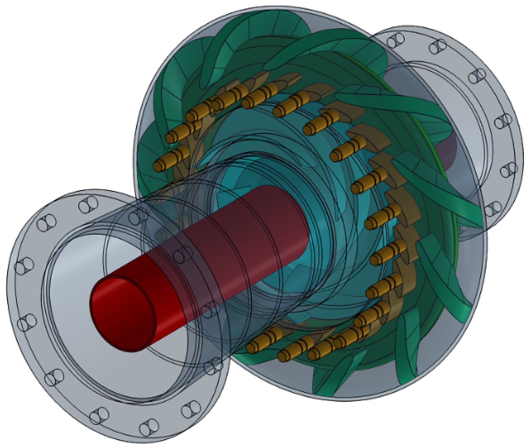
), installed at the Hydraulic Laboratory of the Turbomachinery and Energy Systems research group of the University of Padova. A three-dimensional CAD representation of the complete turbine assembly is shown in
Figure 1.
The analyzed configuration corresponds to turbine-mode operation and was investigated through unsteady simulations of incompressible turbulent flow. All simulations were performed at a constant guide-vane opening angle of 18° (with respect to the fully closed position), as it is associated with unstable behaviour, even in pumping mode. Under these conditions, the radial gap between the guide-vane trailing edge and the runner leading edge is equal to 10.5 mm, corresponding to approximately 5.25% of the runner radius.
The main geometric characteristics and performance parameters of the investigated pump-turbine are summarized in
Table 1 and
Table 2. In particular,
and
denote the runner outlet diameter and channel width, respectively, while
and
refer to the guide-vane inlet diameter and width. The symbols
and
indicate the number of runner blades and guide vanes.
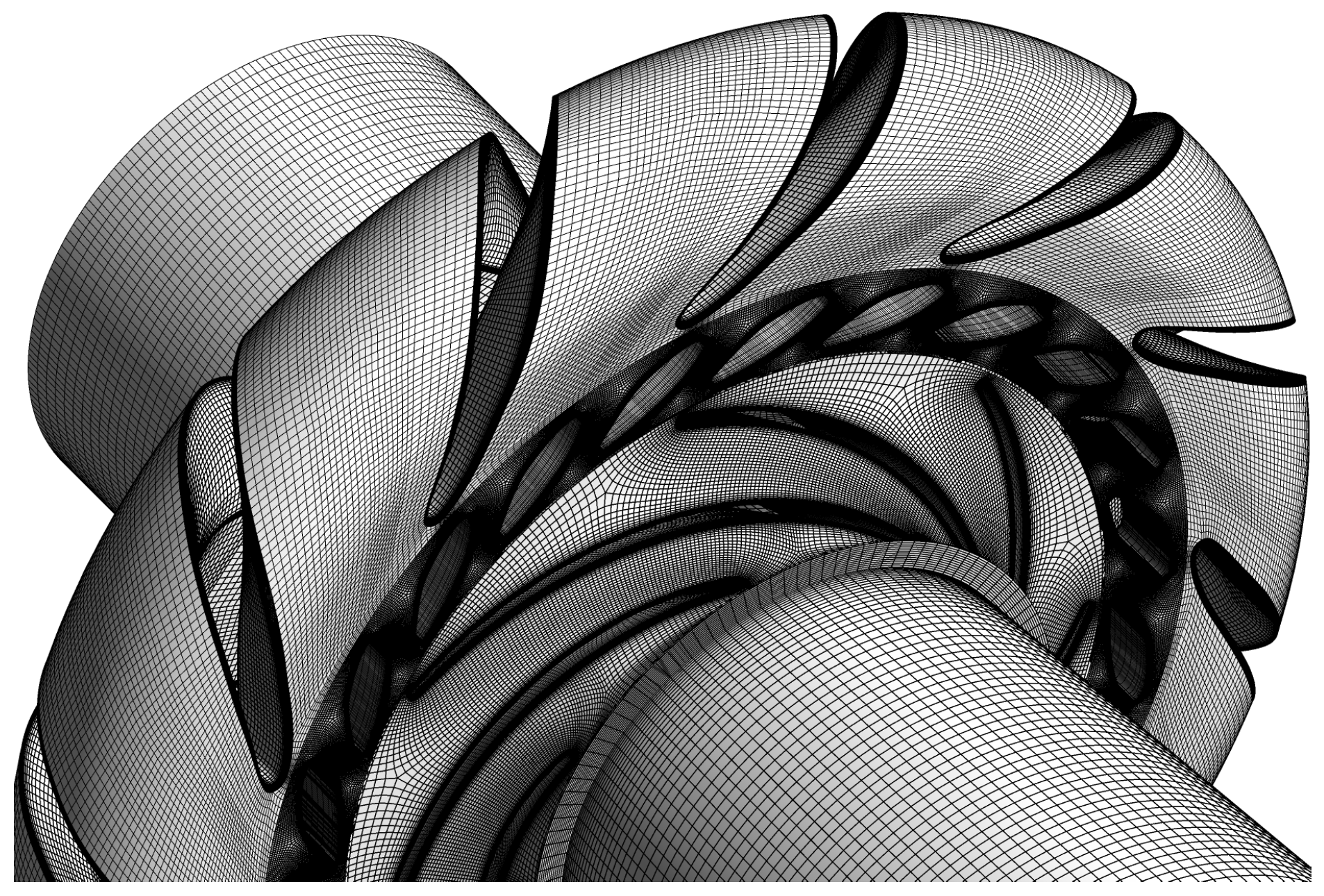
The computational domain was subdivided into five main components: return channel, guide vanes, runner, draft tube, and leakage system. Structured meshes were employed for all components to ensure numerical accuracy and robustness. The return channel, leakage system, and draft tube were discretized using ANSYS ICEM CFD 2024R1, while ANSYS TurboGrid 2024R1 was adopted for the runner and guide-vane domains. Particular attention was devoted to boundary-layer resolution in the runner, guide vanes, and return channel in order to accurately capture flow separation phenomena expected under off-design operating conditions.
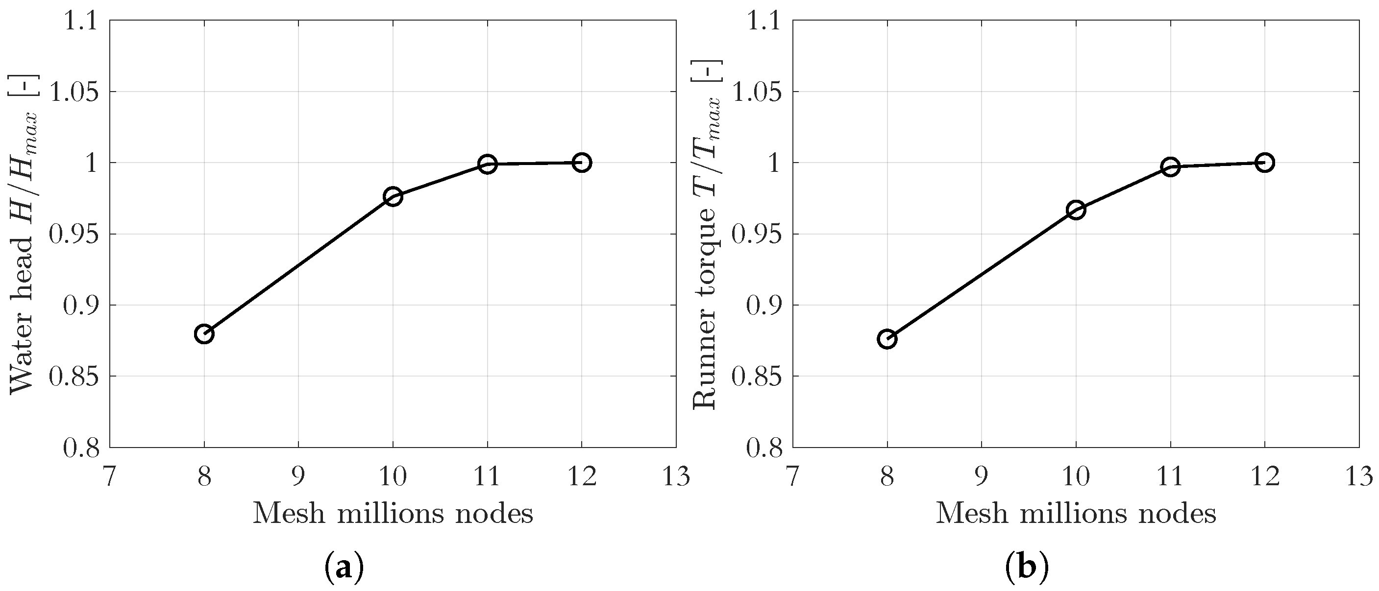
An O-grid topology was adopted for the return channel, whereas an ATM-optimized mesh was used for both the runner and the guide vanes. A mesh sensitivity analysis was conducted to ensure grid independence of the numerical results. The assessment was based on the evaluation of the stage hydraulic head, defined as the total pressure difference between the inlet and outlet of the computational domain, and the runner torque. The analysis was performed at 57% of the best efficiency discharge, a condition selected to optimize the grid for transient simulations approaching the runaway regime.
Four different mesh resolutions were considered, with the total number of nodes ranging from approximately 8 to 12 million. The results of the mesh sensitivity analysis, reported in
Figure 2, indicate that both the hydraulic head and runner torque converge once the mesh size exceeds approximately 11 million nodes.
Detailed mesh statistics for each turbine component are reported in
Table 3. The final mesh consists of approximately 10.8 million nodes, with particular refinement in the runner and guide-vane domains, each comprising about 3.5 million nodes. A representative detail of the adopted mesh is shown in
Figure 3.
2.1. Numerical Settings
The unsteady simulations were performed using the hybrid Scale-Adaptive Simulation Shear Stress Transport (SAS-SST) turbulence model, selected to adequately capture the large-scale unsteady flow structures and separation phenomena expected under deep partial-load and runaway operating conditions. The SAS formulation represents an extension of the Unsteady Reynolds-Averaged Navier–Stokes (URANS) approach, enabling a scale-resolving behaviour in regions characterized by strong flow unsteadiness, while retaining the robustness of the SST model in quasi-steady flow regions.
Compared to Large Eddy Simulation (LES), the SAS-SST model offers a favourable compromise between accuracy and computational cost, making it particularly suitable for industrial-scale turbomachinery applications. Moreover, the model automatically reverts to the standard URANS SST model if the grid resolution is insufficient to resolve the turbulent scales, thus ensuring numerical stability. Nevertheless, to fully exploit the scale-adaptive capabilities of the model, sufficiently long simulation times are required to allow the development of the turbulent structures [
30].
Transient rotor–stator interfaces were employed between rotating and stationary domains. All solid surfaces were treated as no-slip smooth walls. At the inlet of the return channel, a mass-flow-rate boundary condition was imposed, while a static pressure condition was prescribed at the draft-tube outlet. In addition, an opening boundary condition was applied at the draft-tube outlet to accommodate the highly disturbed flow field expected during off-design operation.
A stochastic velocity perturbation corresponding to a free-stream turbulence intensity of 5% was superimposed at the inlet. The runner rotational speed was kept constant and equal to the nominal turbine-mode speed.
Time integration was performed using a second-order backward Euler scheme. The time step was set to correspond to 1° of runner rotation, ensuring adequate temporal resolution of the unsteady flow phenomena while maintaining reasonable computational cost. Spatial discretization of the advection terms was achieved using the high-resolution scheme implemented in ANSYS CFX.
The internal loop coefficient was limited to 4, and the root-mean-square (RMS) residual convergence criteria were set to for the u- and v-momentum equations, for the w-momentum equation, and for the turbulence kinetic energy, providing a reliable compromise between numerical accuracy and computational efficiency.
2.2. Numerical Model Validation
The numerical model was validated by comparing the simulated steady-state performance of the pump-turbine with experimental data, focusing on the water head and hydraulic efficiency. The experimental measurements were conducted at the Turbomachinery and Energy Systems Hydraulic Laboratory of the University of Padova in accordance with ISO and IEC standards.
Global performance measurements were performed under controlled operating conditions, achieving an uncertainty of 0.1% for the water head near the best efficiency point (BEP). In detail, the measurement accuracy was 0.01 m for the water head, 0.2% for the runner torque, and ±0.5 rpm for the rotational speed. All instruments were calibrated on site prior to testing to ensure measurement reliability. A comprehensive description of the experimental setup is provided in [
12].
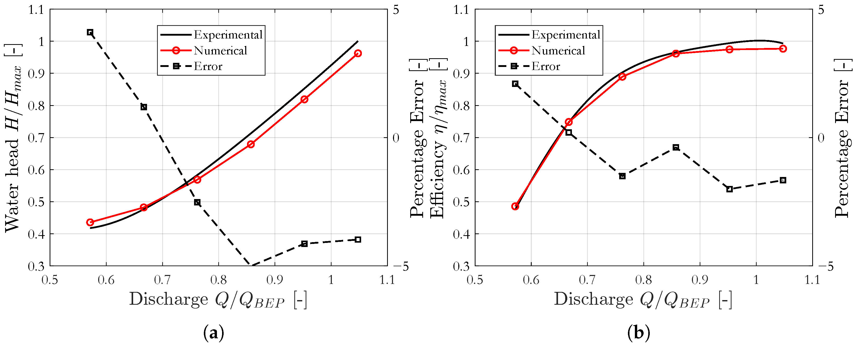
The validation results are presented in
Figure 4a and
Figure 4b, which compare the numerical and experimental characteristic curves in terms of water head and hydraulic efficiency, respectively. The investigated discharge range corresponds to the operational limits of the experimental test rig. Six operating points were simulated using transient calculations at a constant rotational speed of 600 rpm and varying mass flow rates. For each operating point, numerical data were collected over two complete runner revolutions after an initial transient of ten revolutions required to reach a quasi-steady flow regime.
The comparison shows good agreement between numerical predictions and experimental measurements. The maximum deviation in water head remains below 5% over the entire investigated range and decreases to less than 3.5% at the best efficiency point. Similarly, the hydraulic efficiency is predicted with a maximum deviation below 2.5%, while the error at the BEP is smaller than 2%.
Overall, the close correspondence between numerical and experimental results confirms that the adopted numerical approach is capable of accurately reproducing the steady-state performance of the pump turbine. This validation provides a solid basis for the subsequent analysis of unsteady flow phenomena and transient operating conditions.
2.3. Runner Modification Scheme
In the hydraulic design of radial and mixed-flow pumps, blade leaning is a well-established strategy to control secondary flows and redistribute blade loading along the span. Blade lean is introduced by applying a positive or negative rotation of the blade sections around the impeller axis, thereby modifying the relative position of the leading and trailing edges with respect to the meridional plane.
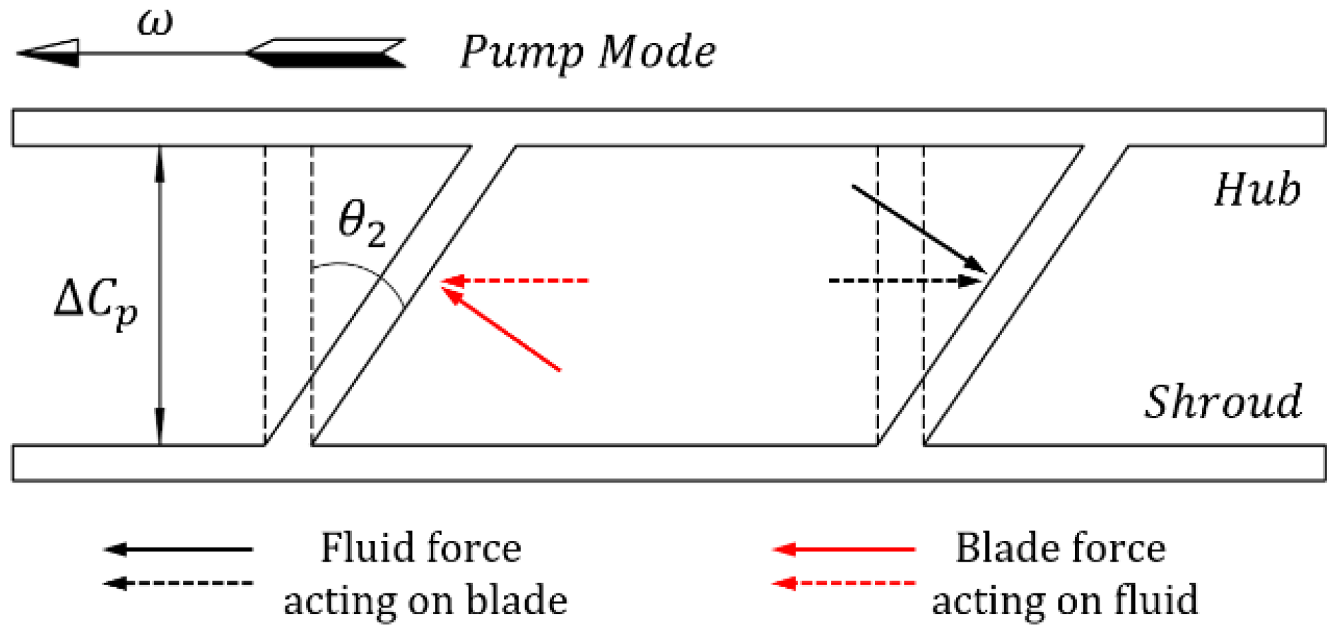
In pump operation, a linear negative lean of the blade trailing edge with respect to the direction of rotation is commonly adopted as illustrated in
Figure 5. This configuration reduces the blade loading near the shroud while increasing it toward the hub at the impeller outlet, leading to a more uniform spanwise flow distribution and mitigating secondary flow development. A detailed discussion of the theoretical background of secondary-flow suppression through blade lean in pumps can be found in [
31].
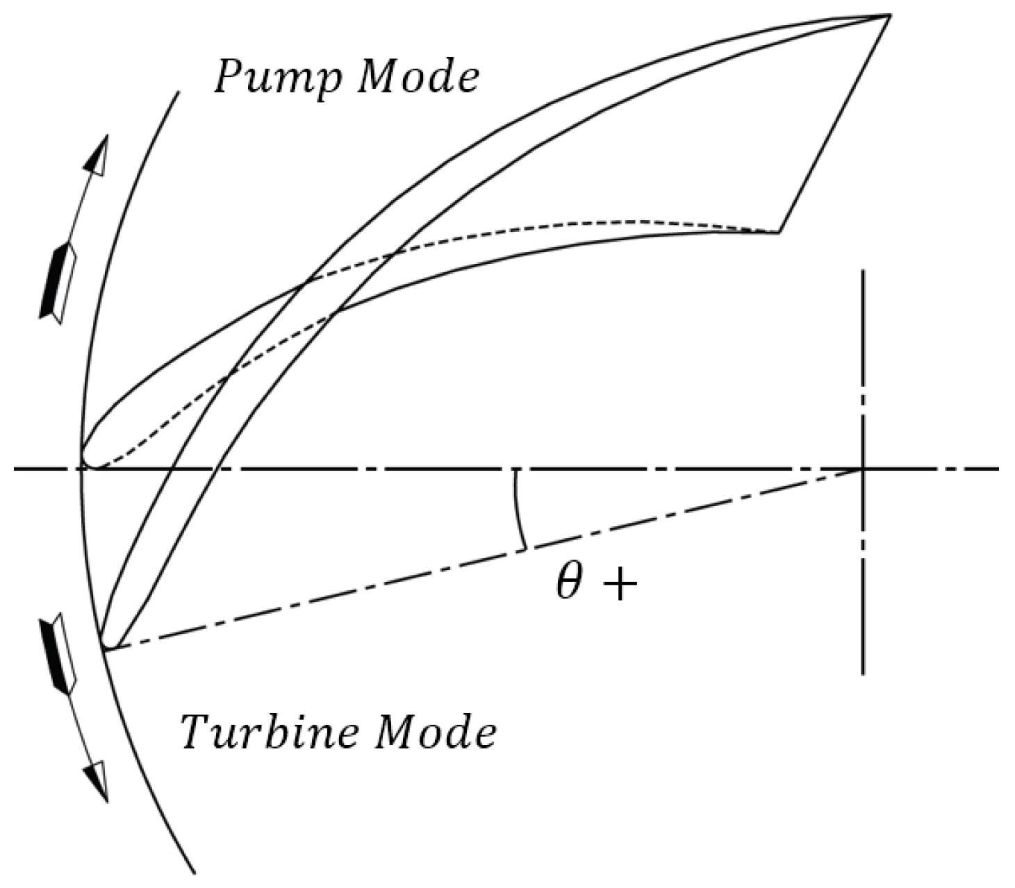
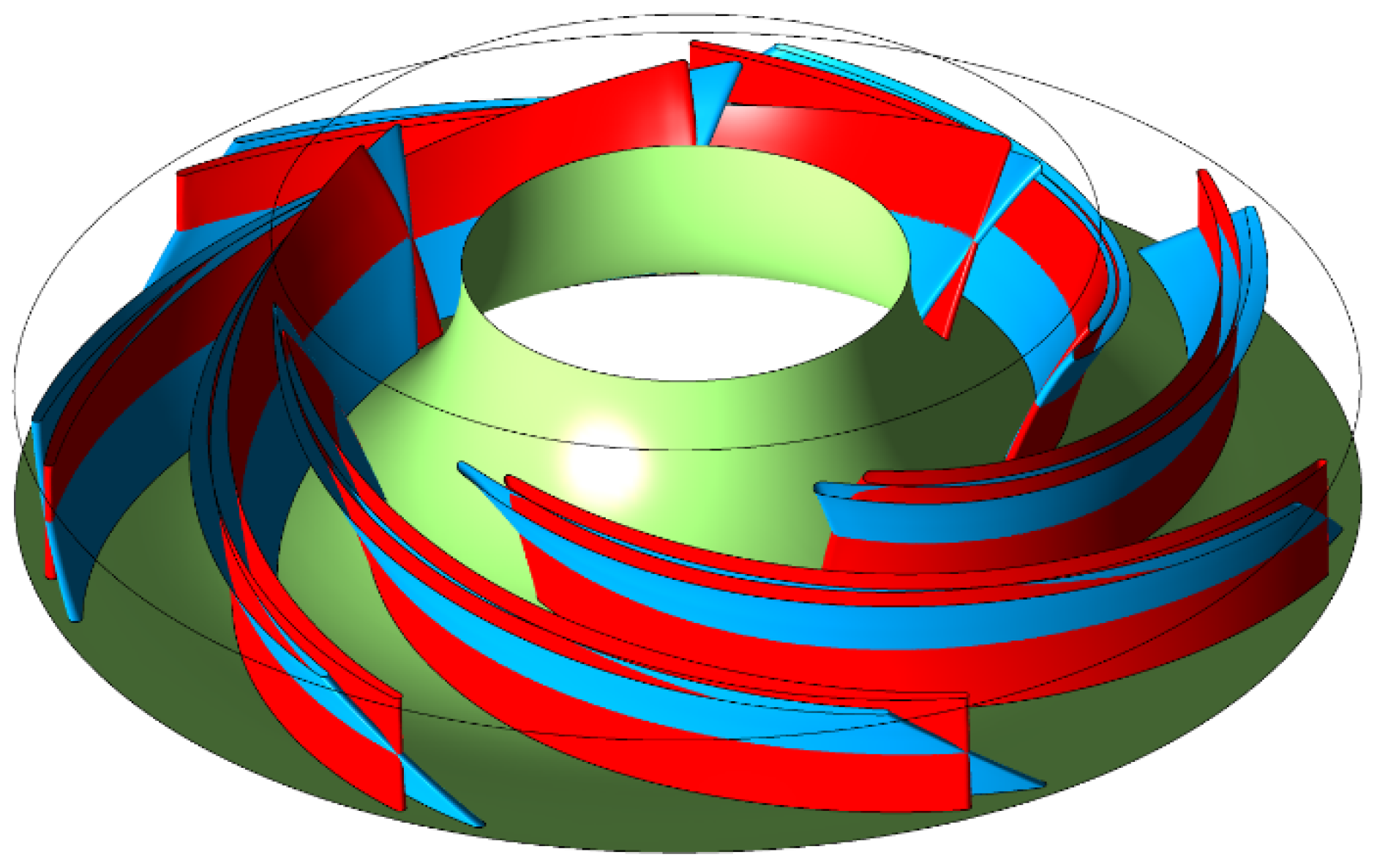
In the present study, a positive lean angle is defined as a rotation of the shroud side of the blade against the runner rotational direction in pump mode, as schematically shown in
Figure 6. Starting from the original runner geometry, characterized by a zero blade lean angle, a linear negative lean of
was introduced. This value was selected as a compromise between the expected hydrodynamic benefits and manufacturing feasibility, avoiding excessive geometric distortion of the blade shape.
The modified runner preserves the same streamwise blade-angle distribution as the original configuration. Moreover, the projections of both the leading and trailing edges in the meridional plane remain unchanged, ensuring that the modification primarily affects the spanwise redistribution of the flow without altering the global flow turning imposed by the runner. A direct comparison between the original and the modified runner geometries is presented in
Figure 7.
This modification strategy allows the influence of blade lean angle to be isolated from other geometric parameters, enabling a focused investigation of its effect on flow stability, pressure fluctuations, and force oscillations under deep partial-load and runaway operating conditions.
2.4. Performance Comparison
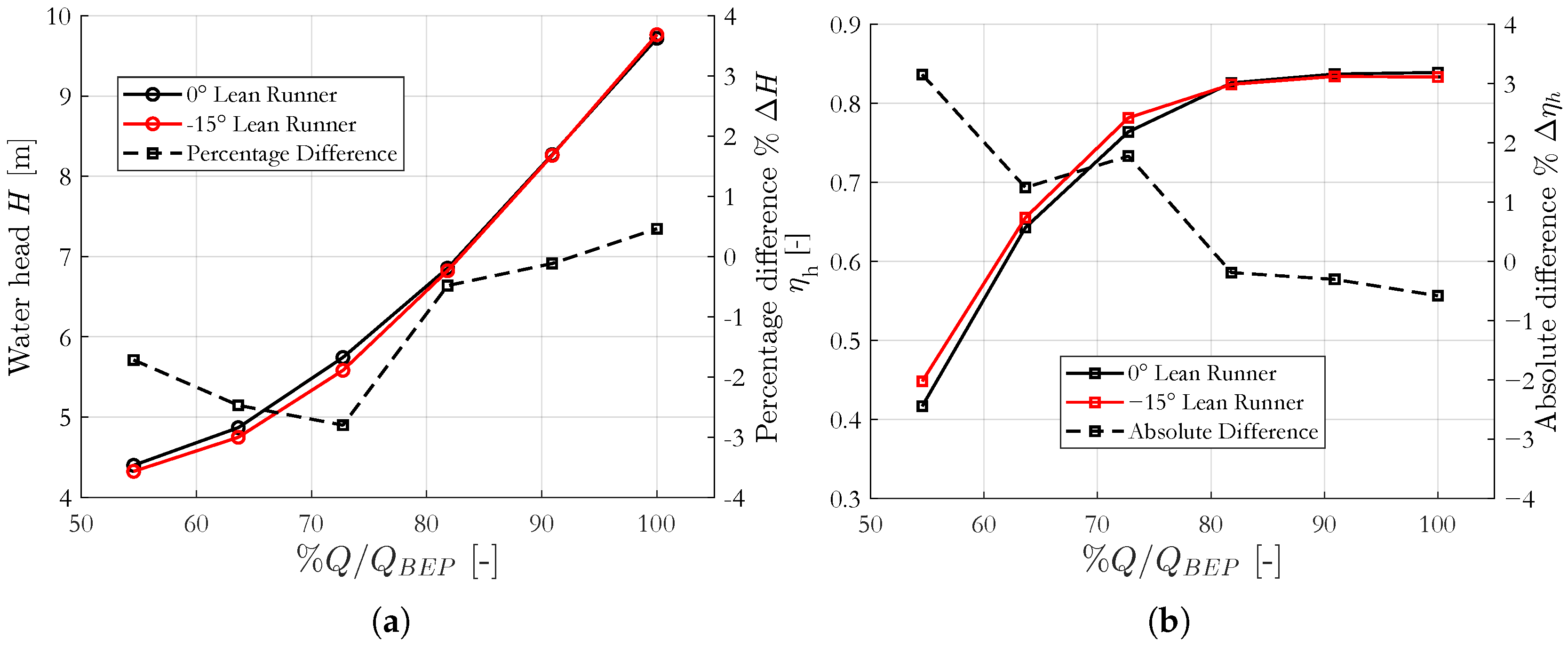
Before addressing the hydrodynamic behaviour of the two runner configurations under deep partial-load and runaway conditions, a preliminary comparison of their steady-state hydraulic performance was carried out. In particular, the original runner (0° lean) and the modified runner with a blade lean were compared in terms of hydraulic efficiency and water head over a range of operating conditions.
Both configurations were simulated at six operating points, corresponding to discharge values between 55% and 100% of the best efficiency discharge
, while keeping the guide-vane opening and the rotational speed constant. For each operating point, the same numerical setup described in the validation section was adopted in order to ensure a consistent comparison. The results of this analysis are reported in
Figure 8a and
Figure 8b for water head and hydraulic efficiency, respectively.
As shown in
Figure 8b, the adoption of a large negative blade lean leads to a systematic improvement in hydraulic efficiency under partial-load operation. The maximum gain is observed at the lowest investigated discharge, where the efficiency increase reaches approximately 3% at 55% of
. This enhancement can be attributed to a more favorable redistribution of the flow within the runner passages, resulting in reduced hydraulic losses under off-design conditions.
Conversely, a slight reduction in efficiency is observed near the nominal operating point. This behaviour is primarily associated with the increased wetted surface and the additional flow deviation introduced by the leaned blades, which lead to higher viscous and secondary-flow losses at high discharge.
The improvement in hydraulic efficiency at partial load is accompanied by a moderate reduction in the water head for discharge values below approximately 80% of
, as shown in
Figure 8a. Since no significant differences in runner torque are observed between the two configurations, this result indicates that the efficiency gain achieved by the negatively leaned runner is mainly related to a decrease in internal hydraulic losses rather than to changes in the energy exchange within the runner.
Overall, this preliminary performance comparison demonstrates that the introduction of a negative blade lean does not compromise the global hydraulic performance of the machine and, on the contrary, provides tangible benefits under partial-load operation.
3. Analysis of the Influence of Runner Lean Angle at Partial Load and Runaway
The steady-state performance analysis highlighted that the adoption of a large negative blade lean angle does not compromise the overall hydraulic efficiency of the pump turbine and, on the contrary, leads to measurable benefits under partial-load operation. However, the most critical operating conditions for reversible pump turbines are associated with deep partial load and the transition toward runaway, where severe unsteady phenomena, flow instabilities, and large pressure and force fluctuations may arise.
For this reason, the present section focuses on a detailed investigation of the unsteady hydrodynamic behaviour of the two runner configurations at the zero-torque condition. Particular attention is devoted to identifying the differences in flow structures, pressure distribution, blade loading, and spectral content of the main hydraulic quantities, with the aim of clarifying the physical mechanisms through which the blade lean angle influences machine stability.
3.1. Boundary Conditions
As discussed in
Section 2.1, the adoption of the hybrid SAS-SST turbulence model requires sufficiently long simulation times to allow the development of unsteady turbulent structures. Moreover, the investigation of the machine behaviour under deep partial load and during the transition toward runaway necessitates a time-dependent formulation of the boundary conditions.
To this end, a transient discharge ramp was imposed at the return-channel inlet by progressively reducing the imposed mass flow rate. This approach makes it possible to reproduce a smooth transition from a stable deep partial-load condition to the zero-torque (runaway) operating point within a single transient simulation, avoiding the need for multiple steady or quasi-steady calculations at different discharge values.
The time evolution of the inlet flow rate was defined according to the following linear law:
where
t denotes the simulation time. Although this discharge evolution does not aim to replicate a real load-rejection event occurring in a full-scale hydropower plant, it provides a sufficiently realistic and controlled framework to investigate the hydrodynamic mechanisms governing the onset of instability in a laboratory-scale configuration.
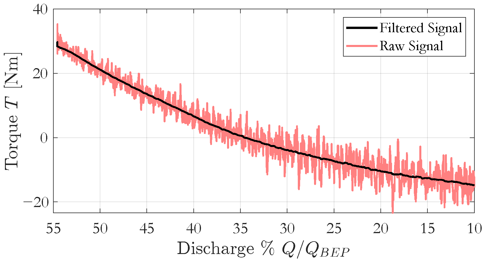
Preliminary simulations were carried out to identify the discharge value corresponding to the runaway condition, defined as the operating point at which the time-averaged runner torque becomes zero. Based on this analysis, the original runner (0° lean) exhibited a runaway discharge of approximately 34% of , whereas the modified runner with a blade lean reached the zero-torque condition at about 33% of .
Due to the strong torque fluctuations characterizing deep partial-load operation, the identification of the runaway condition was performed by applying a moving-average filter to the instantaneous torque signal. This procedure allowed the extraction of a smooth mean torque trend as a function of the decreasing discharge, as illustrated in
Figure 9.
Once the discharge corresponding to zero-torque was identified for each configuration, the simulations were repeated using an updated discharge ramp, initiated after ten complete runner revolutions. This initial period was required to ensure the establishment of a quasi-steady flow field at the starting operating condition. After reaching the runaway regime, the simulations were further extended for an additional twenty runner revolutions, allowing sufficient time for the development and stabilization of the unsteady flow structures associated with the zero-torque condition.
3.2. Fluid Flow Analysis
One of the main effects associated with the introduction of a blade lean angle in pump-turbine runners is the modification of the pressure and velocity distributions along the blade span. Under nominal operating conditions, this effect is typically associated with a redistribution of blade loading and secondary flows. However, under deep partial-load and runaway conditions, the highly disturbed and separated flow field may exhibit a different sensitivity to this design parameter.
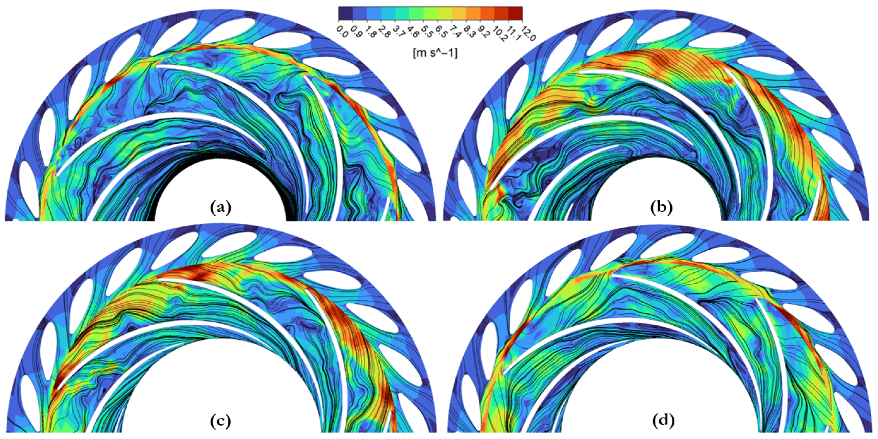
To investigate this aspect, a qualitative and quantitative comparison of the instantaneous flow field within the runner domain was performed for the two investigated configurations at the runaway condition. Particular attention was devoted to the velocity field distribution, flow recirculation patterns, and rotor–stator interaction regions.
Figure 10 shows the instantaneous velocity field and streamlines at 15% and 85% span, reported in absolute reference frame within the guide vanes and in relative reference frame inside the runner, at the zero-torque condition. At 15% span, the runner featuring a
blade lean exhibits a noticeably more orderly flow field (
Figure 10b), with streamlines more closely aligned with the blade surfaces and characterized by higher relative velocity magnitudes. In contrast, the original 0° lean configuration shows a pronounced flow recirculation near the hub region at the runner inlet (
Figure 10a), indicative of severe incidence mismatch and local flow separation.
At 85% span, an opposite trend is observed. In this region, the original runner presents locally higher relative velocities compared to the negatively leaned configuration (
Figure 10c,d), suggesting a redistribution of the incoming discharge toward the shroud side when the lean angle is not applied.
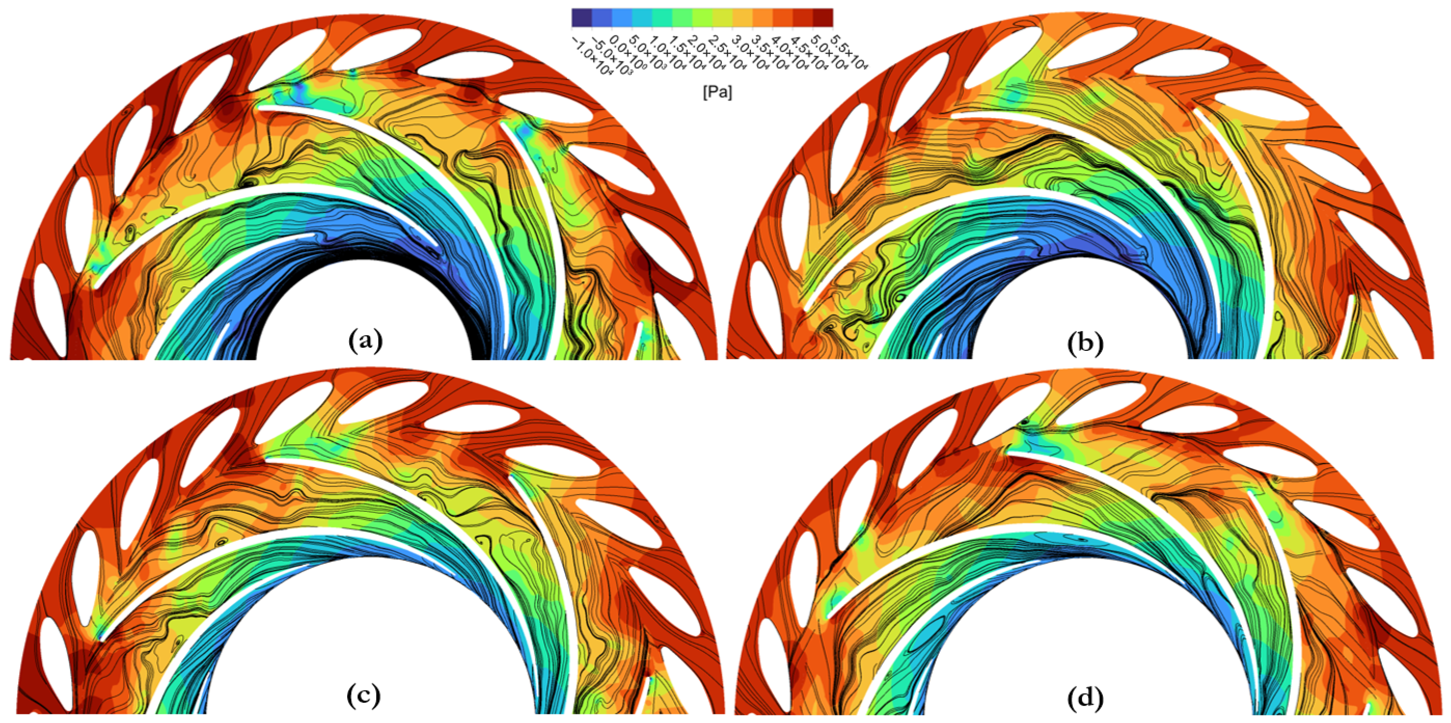
These differences in flow organization are also reflected in the static pressure field.
Figure 11 compares the instantaneous static pressure distributions at 15% and 85% span for both runner configurations under zero-torque conditions. The 0° lean runner exhibits stronger pressure non-uniformities near the hub region (
Figure 11a), particularly in the bladeless region between the guide vanes and the runner leading edge. This behaviour is associated with the intense backflow occurring between adjacent blade passages, which locally increases static pressure and enhances rotor–stator interaction effects.
Conversely, the
lean runner shows a smoother pressure distribution in the same region (
Figure 11b), consistent with a more uniform inlet flow incidence and reduced recirculation intensity.
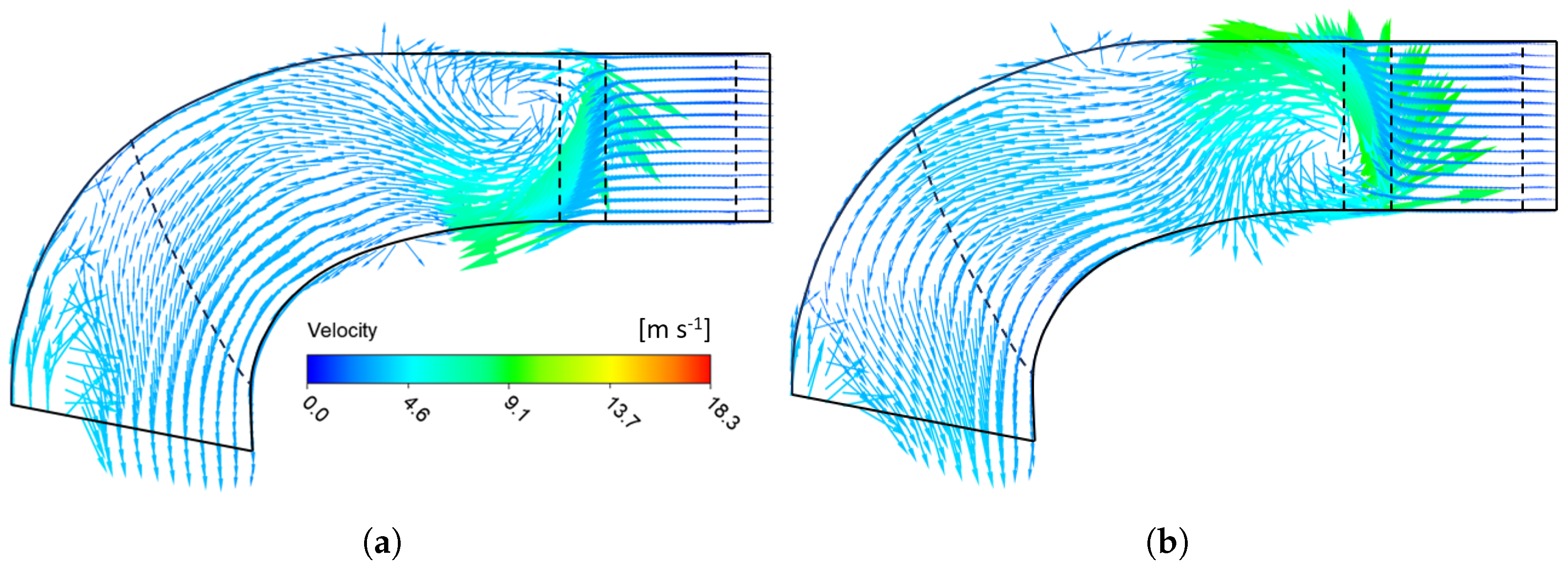
Further insight into the influence of blade lean on the internal flow structure is provided by the meridional velocity field.
Figure 12 presents the area-averaged velocity vectors in the meridional plane at the runaway condition. Both configurations are characterized by a large recirculating region at the runner inlet; however, the orientation and intensity of this recirculation differ markedly.
In the original runner, a strong backflow develops near the hub surface, while the lean configuration exhibits a reversed pattern, with reduced backflow intensity at the hub and a comparatively more stable flow structure. At the runner outlet, the original geometry again displays a more pronounced backflow region, whereas the negatively leaned runner maintains a more homogeneous discharge distribution.
These observations indicate that, even under highly chaotic flow conditions such as those characterizing the runaway regime, the blade lean angle remains an effective design parameter capable of significantly influencing the internal flow organization. In particular, the adoption of a large negative lean angle promotes a redistribution of the discharge toward the hub region and weakens rotor–stator interaction mechanisms, thereby contributing to improved hydrodynamic stability.
3.3. Blade Load Analysis
To quantitatively assess the influence of the blade lean angle on the runner loading, the pressure distribution acting on the runner blades was analyzed for both configurations. The analysis was carried out at three representative spanwise sections, located at 15%, 50%, and 85% of the blade height, and for two operating conditions: a stable deep partial-load condition (55% ) and the zero-torque (runaway) condition (34–33% ).
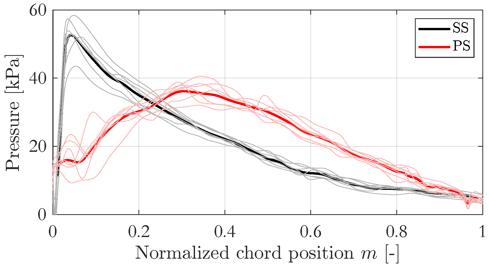
Given the strongly unsteady and highly disturbed flow field characterizing these operating regimes, the pressure distributions were evaluated as blade-averaged quantities. Specifically, the instantaneous pressure signals were extracted for each blade and subsequently averaged in time and across the blade set, in order to obtain a representative and physically meaningful load distribution. An example of the adopted averaging procedure is shown in
Figure 13, referring to the mid-span pressure distribution of the original runner at runaway conditions.
The comparison between the pressure distributions at deep partial load for the original (0° lean) and modified (
lean) runners is reported in
Figure 14. At this operating condition, both configurations exhibit a crossing between the pressure-side (PS) and suction-side (SS) pressure distributions over the first portion of the blade chord. This behaviour indicates the presence of negative torque contributions over approximately 18–22% of the blade surface, associated with a large incidence angle at the blade inlet and the onset of flow separation in the leading-edge region.
In this regime, the stagnation point shifts toward the suction side of the blade, confirming the occurrence of stall-like phenomena. While the general shape of the pressure distributions remains similar between the two configurations, the negatively leaned runner shows a slightly reduced pressure difference between PS and SS near the hub region, suggesting a more favorable inlet flow alignment.
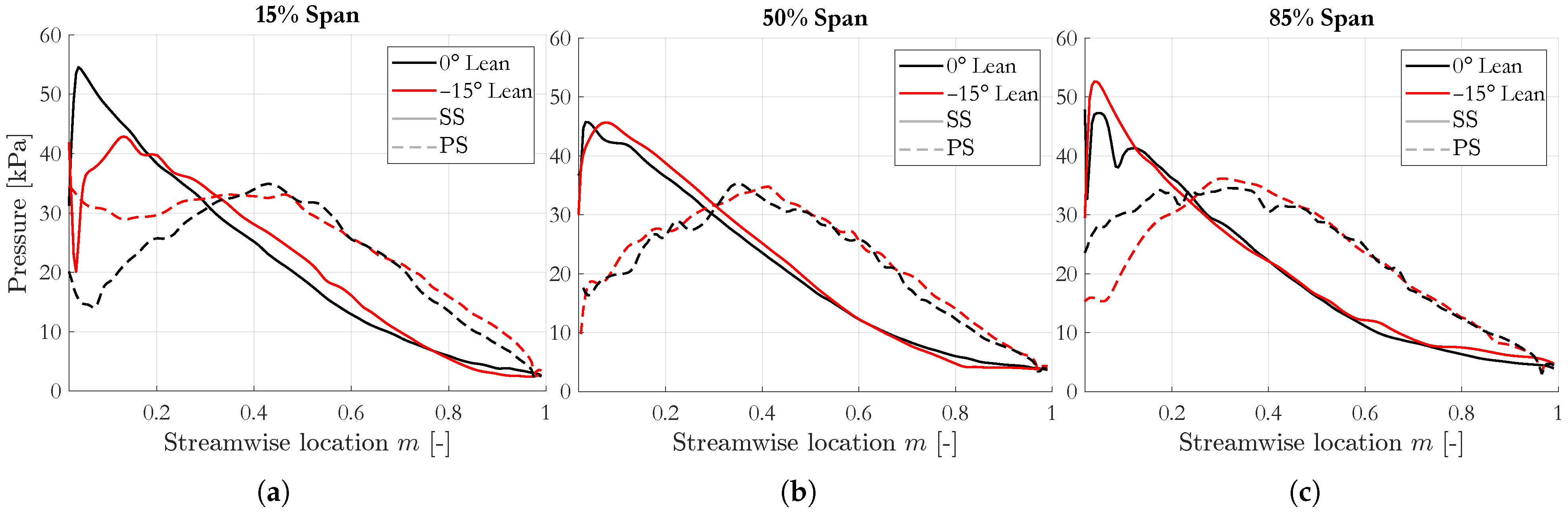
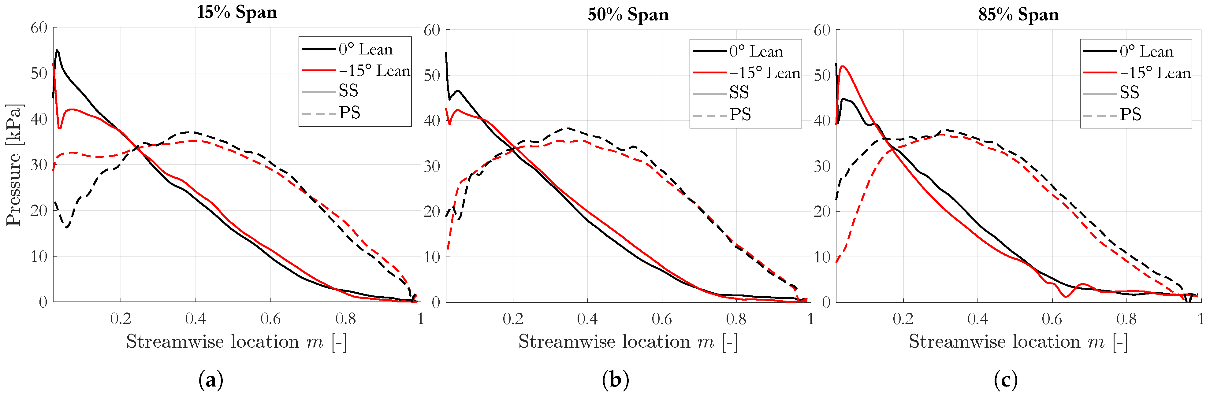
The pressure distributions evaluated during the runaway condition are presented in
Figure 15. As expected, the extent of the blade surface affected by negative torque increases under zero-load operation, reaching approximately 25–30% of the blade chord for both runners. At mid-span (50%), no significant differences are observed between the two configurations, indicating that the influence of blade lean is limited in this region under highly disturbed flow conditions.
More pronounced differences emerge at 15% span. In this section, the lean runner exhibits higher pressure levels on the suction side starting from approximately 20% of the chord, while simultaneously showing higher pressure on the pressure side for chordwise positions below 40%. As a result, the overall pressure difference between PS and SS is reduced compared to the original runner, particularly near the hub region. This behaviour is consistent with the improved flow incidence and reduced backflow intensity observed in the fluid flow analysis.
Conversely, at 85% span the original runner presents a reduced pressure difference between PS and SS with respect to the negatively leaned configuration, especially in the leading-edge region. This result reflects the redistribution of the incoming discharge toward the shroud side observed for the 0° lean runner and further confirms the spanwise reorganization of the flow induced by the blade lean angle.
The link between blade loading and internal flow structure becomes evident when considering the discharge distribution along the blade span. As highlighted in
Figure 10, the two runners exhibit opposite trends: the original configuration shows a concentration of flow toward the shroud, whereas the negatively leaned runner promotes a higher flow rate near the hub. This redistribution leads to a more favorable incidence condition at the blade inlet for the
lean runner, thereby reducing the pressure difference between the PS and SS in the hub region and mitigating the severity of stall-related phenomena.
Overall, the blade load analysis confirms that the adoption of a large negative blade lean angle significantly alters the spanwise load distribution, even under highly unsteady operating conditions such as deep partial load and runaway. By reducing pressure gradients near the hub and improving inlet flow alignment, the negatively leaned runner exhibits a more balanced blade loading, which contributes to the enhanced hydrodynamic stability observed in the subsequent spectral analysis.
4. Spectral Characterization
To further quantify the influence of the runner blade lean angle on the unsteady hydrodynamic behaviour of the machine under zero-torque conditions, a spectral analysis was performed on the main global hydraulic quantities obtained from the transient simulations. In particular, the frequency content of the water head, runner torque, and radial forces acting on the runner was investigated by means of Fast Fourier Transform (FFT).
During the transient simulations, the monitored signals were sampled at a frequency of 3600 Hz, corresponding to an angular resolution of of runner rotation. The analysis was conducted over a time window spanning 20 complete runner revolutions after the attainment of the zero-torque condition, resulting in a minimum resolvable frequency of 0.5 Hz.
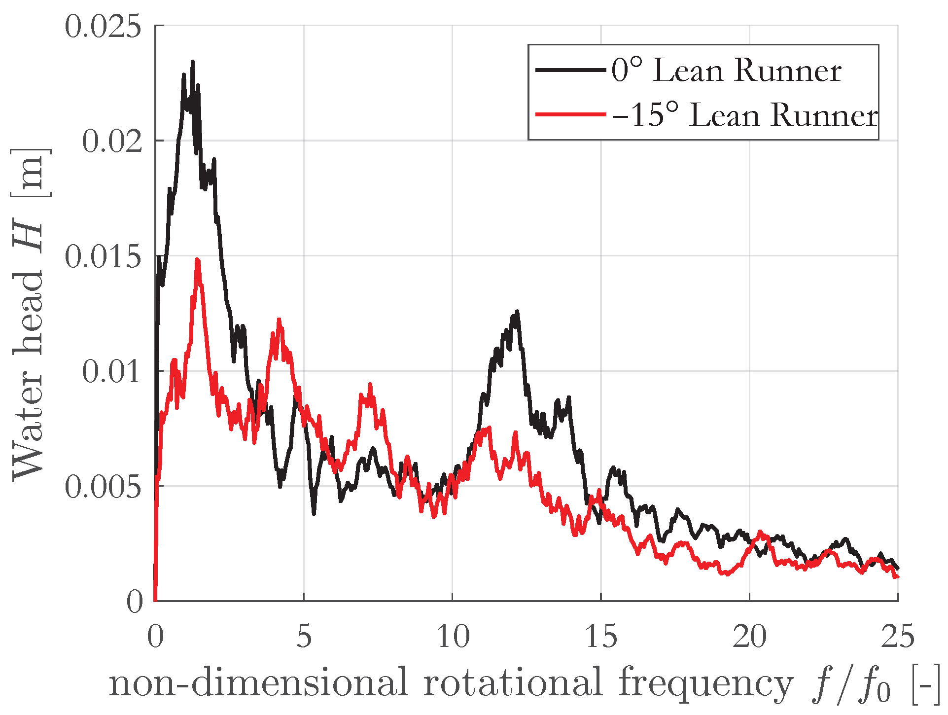
Figure 16 compares the frequency spectra of the water head for the 0° and
lean runner configurations. The spectra were post-processed using a moving-mean filter to improve readability. The frequency axis is reported in dimensionless form, normalized by the runner rotational frequency
Hz. As shown, both configurations exhibit two dominant frequency components located at approximately
(11 Hz) and
(110 Hz), respectively.
These oscillations are attributed to rotor–stator interaction effects between the runner blades and the guide vanes. Although the same frequency components are present in both cases, the amplitude of the pressure fluctuations is significantly higher for the 0° lean runner, with peak values nearly twice those observed for the negatively leaned configuration. Nevertheless, the absolute magnitude of these perturbations remains relatively limited, indicating a moderate influence on the overall hydraulic behaviour of the machine.
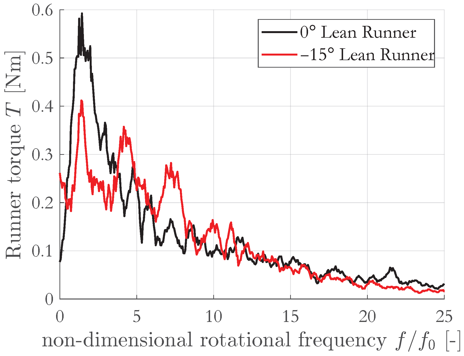
A similar trend is observed in the frequency spectrum of the runner torque, reported in
Figure 17. In both configurations, the torque signal exhibits a low-frequency content distributed in the range between approximately 10 and 25 Hz. Once again, the 0° lean runner shows a higher sensitivity to torque oscillations, although the overall amplitude of these fluctuations remains relatively small.
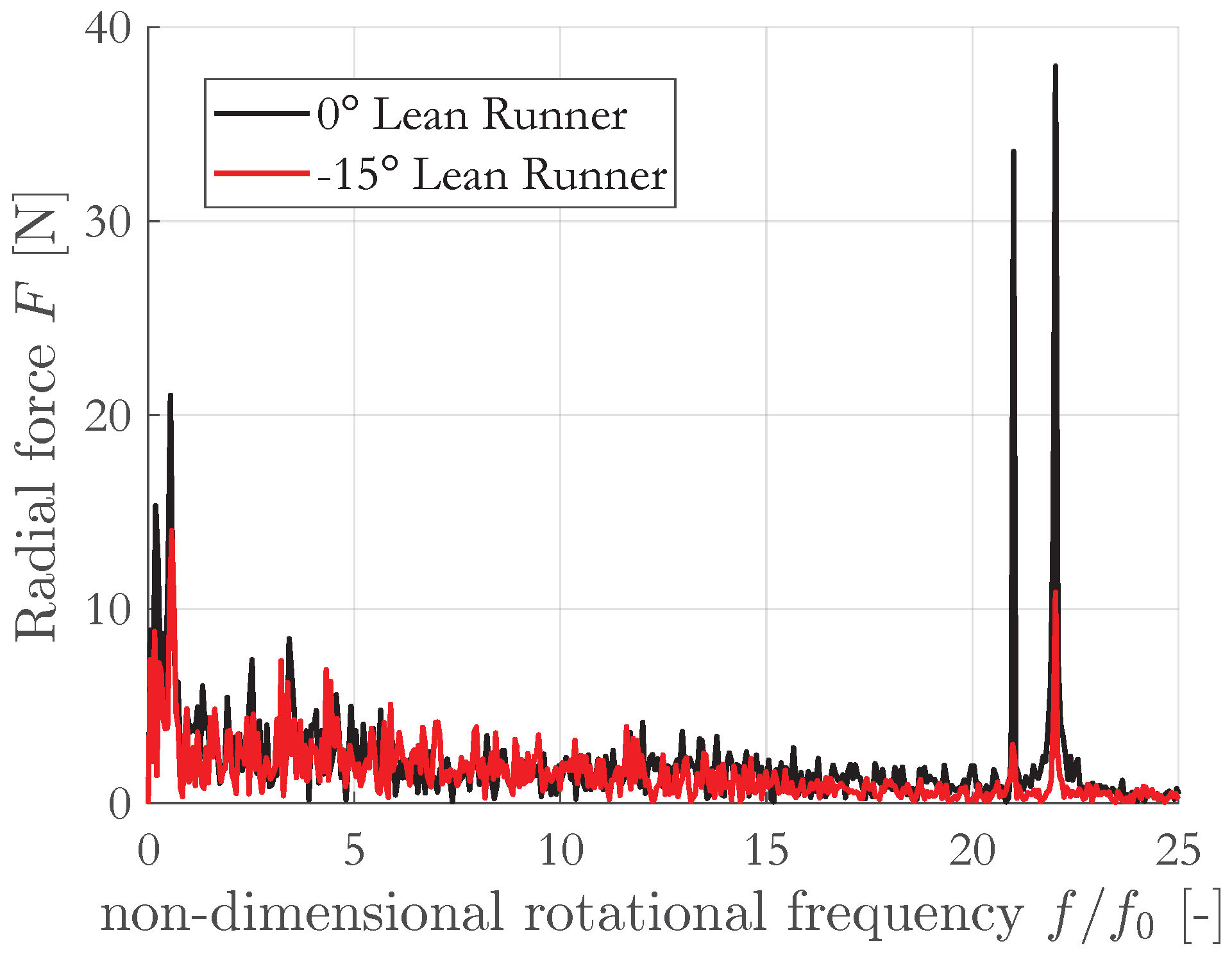
More pronounced differences between the two configurations emerge when analyzing the frequency spectrum of the radial force acting on the runner in the
x-direction, as shown in
Figure 18. For the 0° lean runner, high-amplitude peaks are observed at frequencies corresponding to
and
. While the same frequency components are also present in the spectrum of the
lean runner, their amplitudes are substantially reduced. In particular, the peak at
is approximately four times lower compared to the original configuration.
The frequency component at
can be directly associated with the rotor–stator interaction between the runner and the guide vanes. Conversely, the origin of the perturbation at
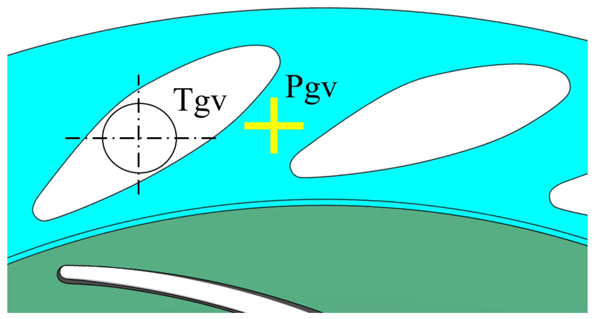
is less straightforward and required further investigation. To clarify this aspect, the spectral analysis was extended to the torque acting on a single guide vane pivot (T
GV) and to the static pressure signal acquired at a control point located within the guide-vane passage at mid-span (P
GV). The location of these monitoring points is illustrated in
Figure 19.
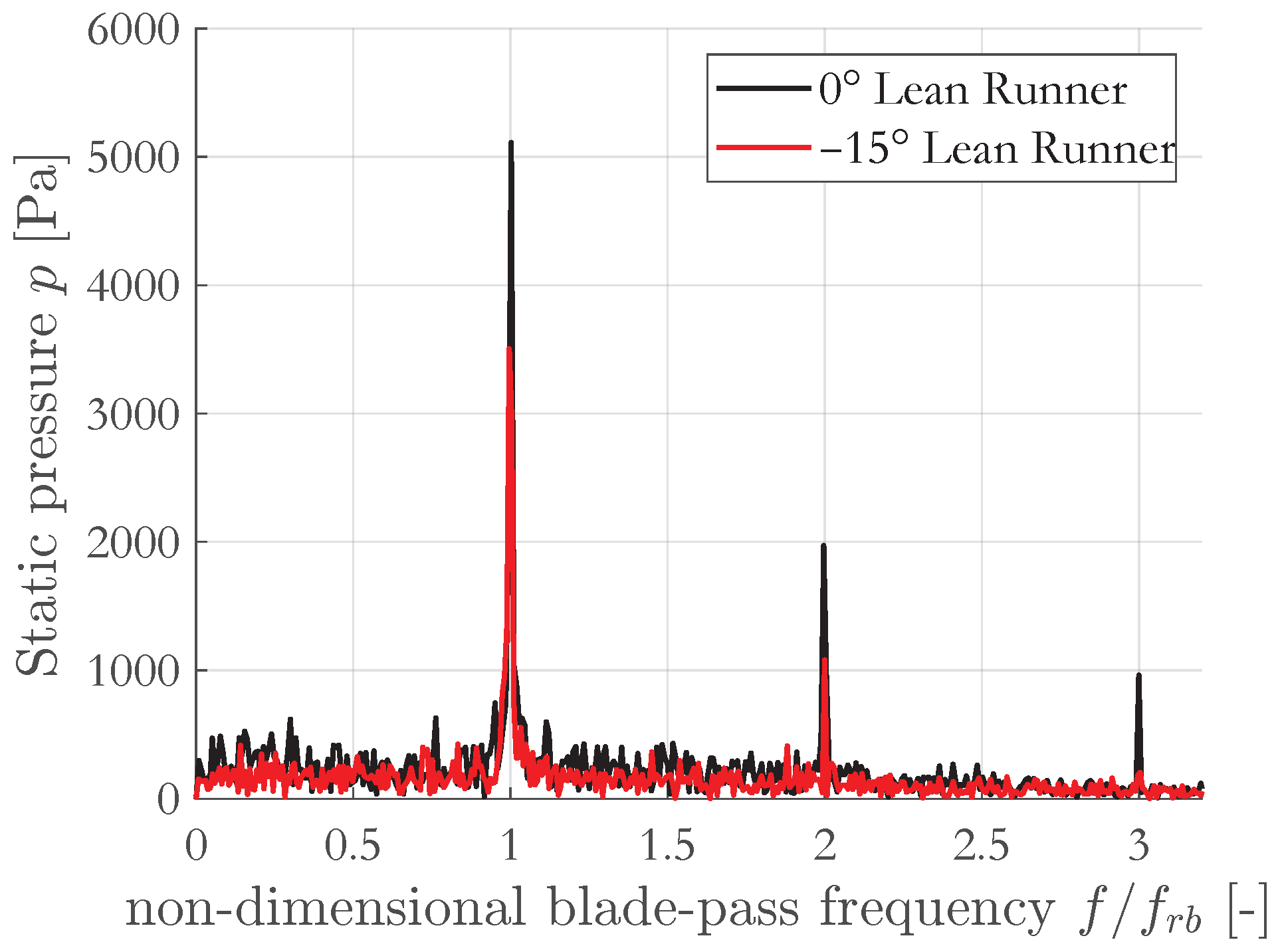
Figure 20 presents the frequency spectrum of the static pressure signal measured at P
GV. In both configurations, the spectrum is dominated by a strong peak at the runner blade-passing frequency
Hz, where
is the number of runner blades. Additional peaks corresponding to the second and third harmonics of the blade-passing frequency are also visible.
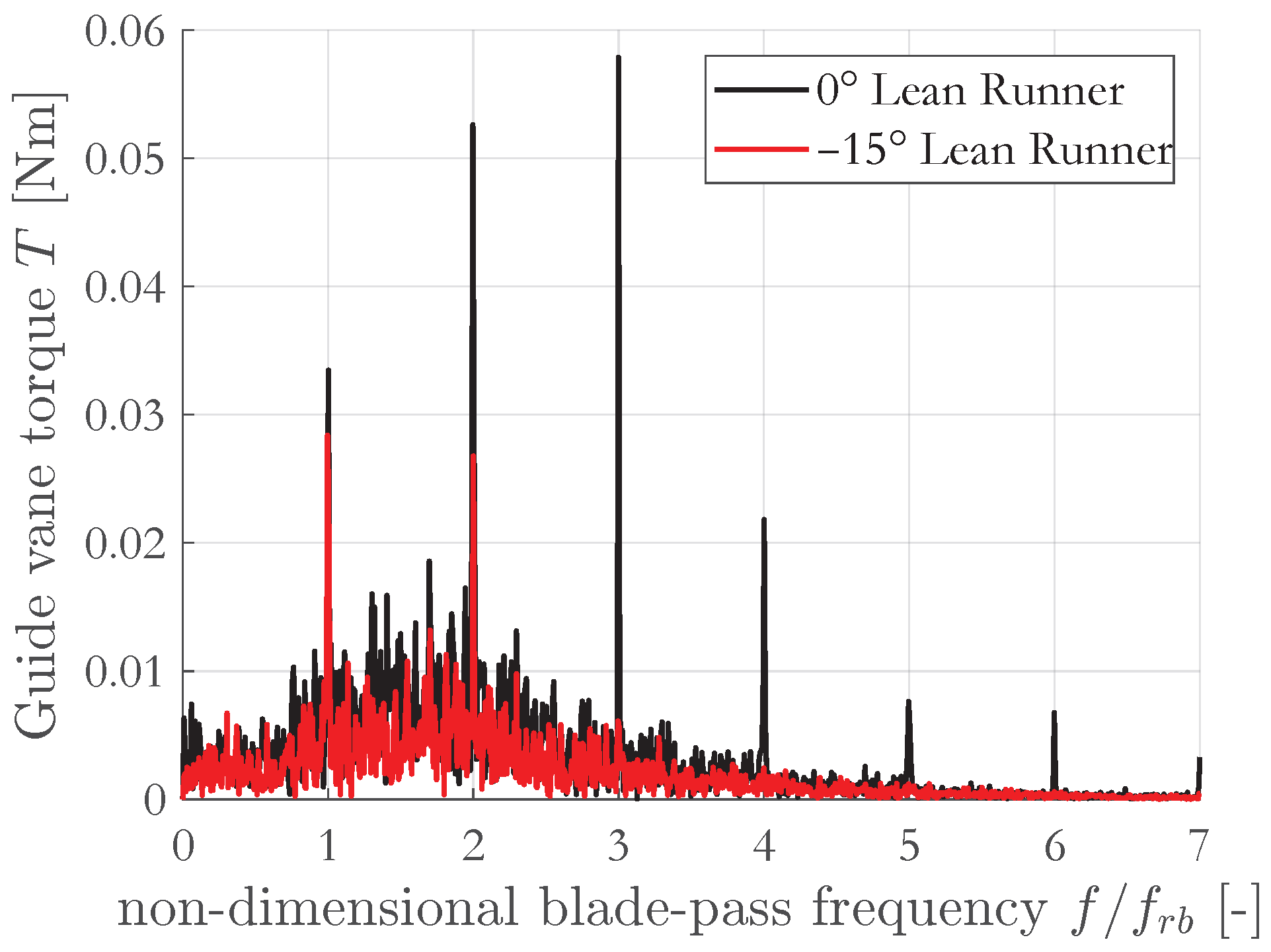
The same frequency components are observed in the torque spectrum of a single guide vane, shown in
Figure 21. While both runners exhibit comparable amplitudes at the fundamental blade-passing frequency, the higher harmonics are significantly more pronounced in the 0° lean configuration. In particular, the third harmonic at
is almost completely suppressed in the
lean runner.
Based on these results, the high-amplitude perturbation observed at 21– in the radial force spectrum of the original runner can be attributed to the propagation of higher harmonics of the blade-passing excitation through the rotor–stator interaction. In contrast, the negatively leaned runner effectively suppresses the third harmonic of the blade-passing frequency. This behaviour is likely related to the broader angular distribution of the runner blade leading edges, which nearly spans the entire pitch of the guide vanes (), thereby reducing the coherence of the excitation mechanism.
Overall, the spectral analysis clearly demonstrates that the runner with a 0° blade lean angle is significantly more sensitive to rotor–stator interaction and high-frequency excitation under zero-torque conditions. The adoption of a large negative blade lean angle leads to a substantial attenuation of force and pressure fluctuations, particularly at higher harmonics, resulting in a marked reduction of vibration and acoustic excitation. This represents a key improvement in terms of operational stability for reversible pump turbines operating under deep partial load and runaway conditions.
5. Conclusions
This study investigated the influence of runner blade lean angle on the hydrodynamic behaviour of a reversible pump turbine operating under deep partial-load and zero-torque conditions. Two runner configurations were analyzed through high-fidelity transient numerical simulations: the original geometry with zero blade lean and a modified design featuring a large negative lean angle of .
The results demonstrate that the adoption of a negative blade lean significantly improves machine stability in the most critical operating regimes. Although both runners exhibit highly unsteady flow structures and pressure fluctuations when approaching the runaway condition, the negatively leaned configuration shows a consistently more favorable behaviour. In particular, the redistribution of the incoming discharge toward the hub region leads to improved flow incidence at the blade inlet, reduced backflow intensity, and a more balanced spanwise blade loading.
From a quantitative standpoint, the negative lean runner exhibits lower pressure gradients between the pressure and suction sides of the blades near the hub, mitigating stall-related phenomena and reducing the extent of blade regions subjected to negative torque. These effects are reflected in the spectral analysis, which reveals a substantial attenuation of pressure, torque, and radial force fluctuations. The most significant improvement is observed at higher harmonic frequencies associated with rotor–stator interaction, where the negatively leaned runner effectively suppresses the third harmonic of the blade-passing frequency, leading to a marked reduction in vibration and acoustic excitation.
Despite the highly disturbed flow field characterizing the runaway condition, the blade lean angle remains an effective design parameter in influencing the internal flow organization and the dynamic response of the machine. The observed reduction in unsteady loads and high-frequency excitations highlights the potential of negative blade lean configurations to enhance the operational stability and reliability of reversible pump turbines.
In conclusion, the present work provides new physical insight into the mechanisms through which blade lean angle affects flow instabilities in reversible pump turbines. The findings confirm that a large negative blade lean represents a promising design strategy to mitigate deep partial-load and runaway instabilities, thereby supporting the increasing demand for flexible and reliable operation in pumped hydro energy storage systems. Future work will focus on extending the analysis to different guide-vane openings and investigating the interaction between blade lean and other geometric design parameters.