1. Introduction
The growing scarcity of fossil fuels and the associated impact on global climate present new challenges within the energy sector. Turbomachinery accounts for a substantial share of global energy conversion, so even single-digit percentage improvements in aerodynamic efficiency translate directly into fuel savings and emission reductions. However, given that, e.g., aircraft engines or stationary gas turbines already operate efficiently with component efficiencies exceeding , further improvement poses significant challenges.
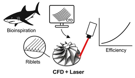
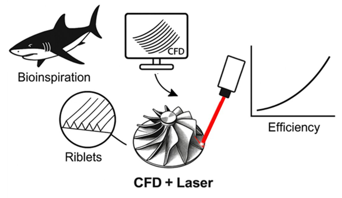
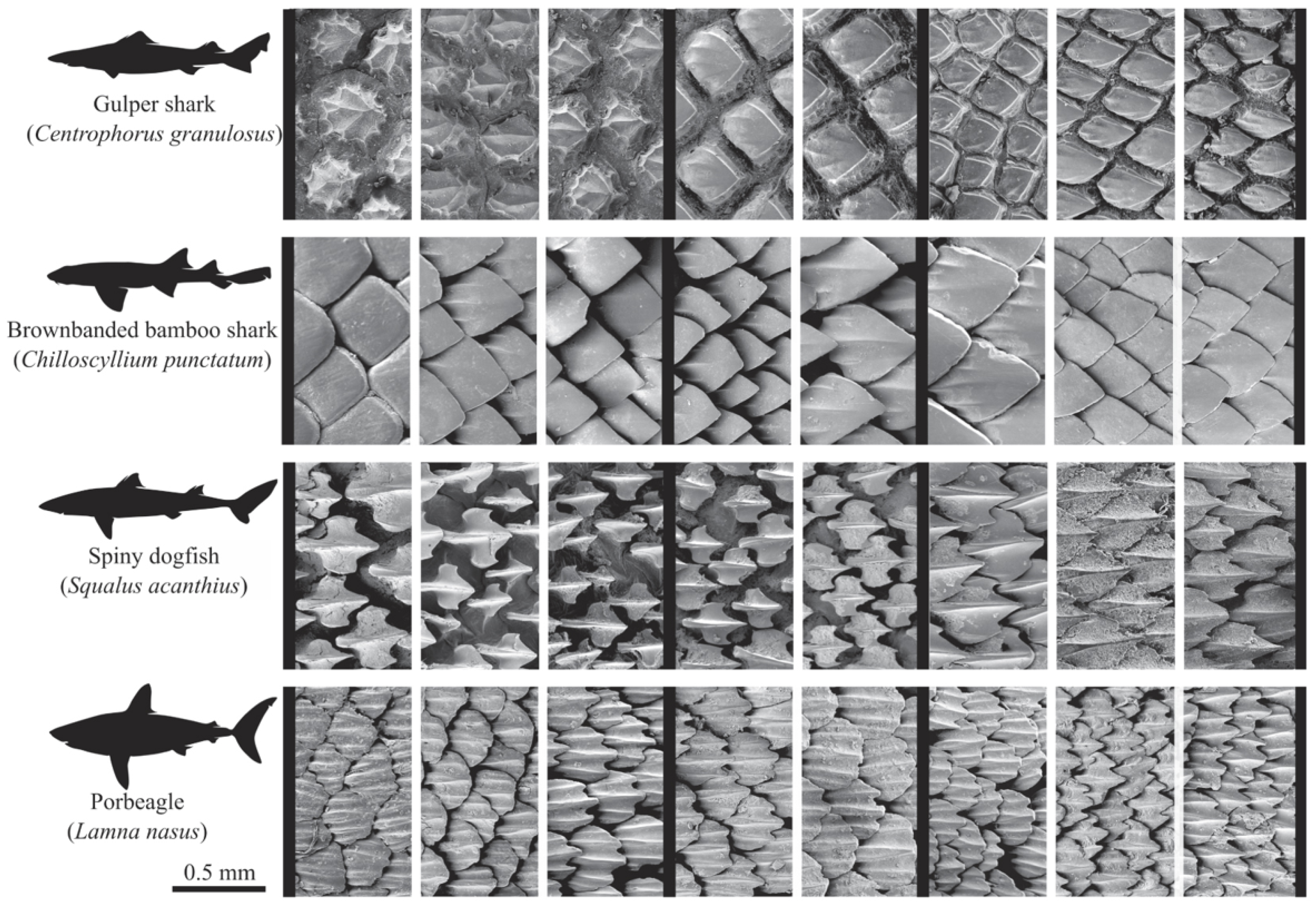
For turbomachinery a large fraction of aerodynamic losses arises from viscous drag. For this reason, active and passive flow-control strategies have been increasingly investigated since the oil crisis in the 1970s. A promising approach to reduce skin friction of turbulent flows by passive means consists of the application of surface grooves in the micro-scale range aligned with the near-wall flow, so-called riblet structures. These structures, initially inspired by the dermal denticles of fast-swimming sharks (
Figure 1), are capable of inhibiting the spanwise motion of near-wall vortices [
1,
2,
3].
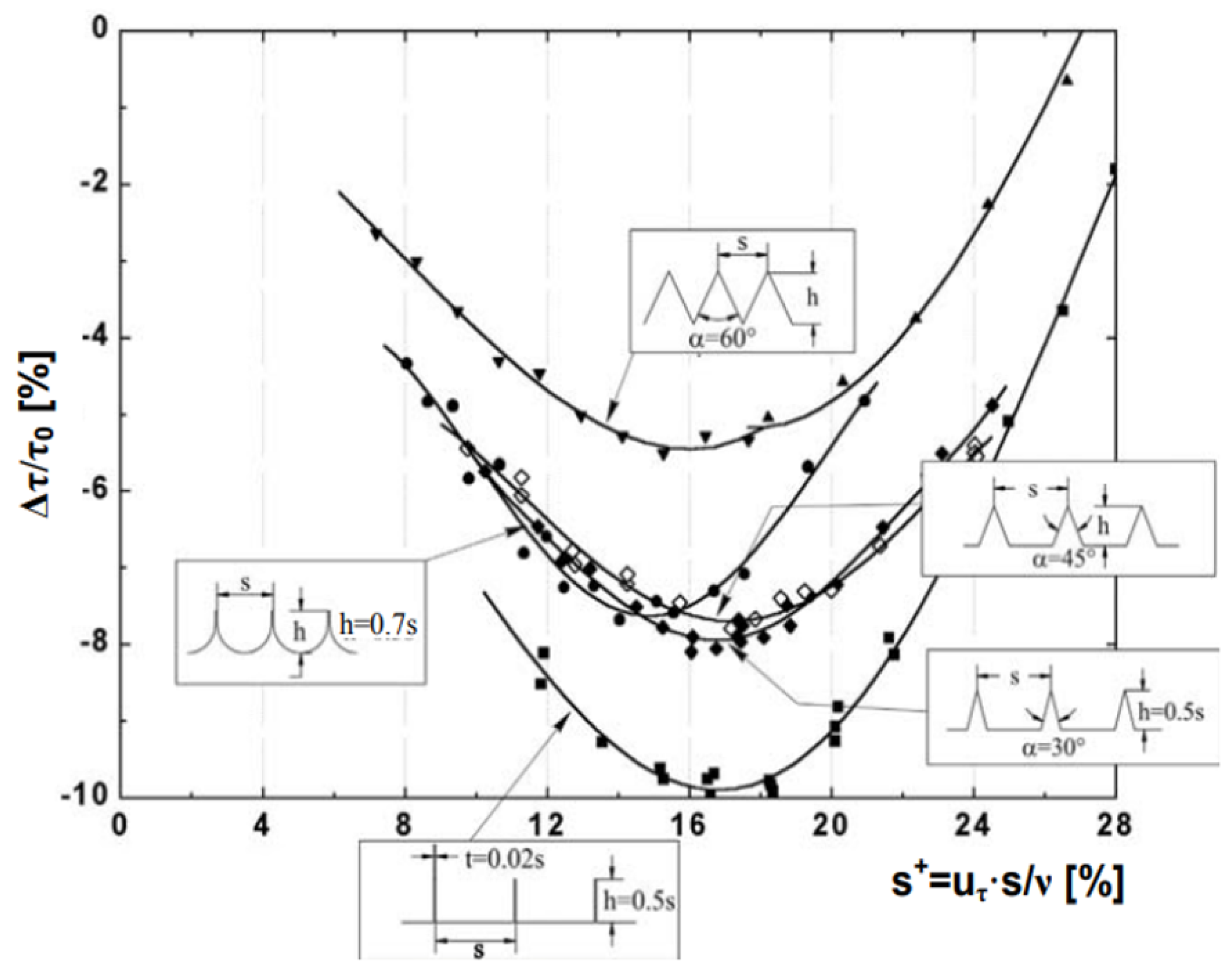
Systematic investigations on how different cross-sectional groove shapes affect drag reduction in turbulent flat plate boundary layers were conducted by [
1,
3,
5]. The investigations included riblets with triangular, scalloped, trapezoidal and blade-shaped grooves. The corresponding wall shear stress reduction
was summarized by [
3] (see
Figure 2). Accordingly, the highest wall shear stress reduction, in the order of
, can be achieved for blade-shaped riblets. However, due to their low mechanical durability, these structures are less suitable for the applications outside laboratory conditions. Therefore, ref. [
3] suggested the application of trapezoidal-shaped grooves. These structures, specifically devised for aircraft application, can withstand the stress while maintaining a high drag-reducing potential in the range of
.
Despite these promising results, the practical use of riblets in technical applications remains limited. Classical demonstrations typically rely on flat plates [
3,
6] or simple airfoils with uniform riblet geometry [
7,
8]. Experimental data on the effects of riblets for turbomachinery applications are still rare [
9,
10,
11,
12] due to the enormous challenges connected. Furthermore, the efficiency gain is unclear, since secondary flow effects and flow separations may be present. The influence of riblet structures on these secondary flow phenomena has not yet been sufficiently investigated. However, the key issue is that in contrast to the flat plate, turbomachinery blades present strongly three-dimensional, spatially varying flow conditions. Under such conditions, uniform riblets can be misaligned or off-scale, eroding the expected benefit. Therefore, manufacturing technologies would be required that offer a high degree of flexibility in terms of size and orientation, combined with high precision in industrially relevant temporal and spatial scales.
To minimize production effort, ref. [
13] examined triangular riblets of uniform geometry over the entire surface of the highly loaded compressor cascade V103-180 and quantified their effect on the loss behavior across
. With riblets applied, the pressure-loss coefficient decreased by about 6 to
. Studies on compressor blades with riblets adjusted in stages manufactured by grinding or laser processing were conducted by [
14,
15]. Cascade wind-tunnel measurements at the Institute of Turbomachinery and Fluid Dynamics (TFD) at the Leibniz University Hannover confirmed the positive effect of riblet application, showing overall single-digit percentage reductions in the pressure-loss coefficient. Consistently, ref. [
15] reported an additional decrease in the pressure-loss coefficient in the range of
.
The present study is an extended version of a conference paper presented at the 16th European Turbomachinery Conference (ETC16) [
16]. Building on thechallenges identified, the work combines simulation-guided design with a novel laser-based manufacturing method developed at the Laser Institute of Mittweida (LHM). As application scenario the flow around the NACA0012 airfoil is considered as there is an established database on the loss behavior of riblets. The end-to-end approach is intended to be directly transferable to turbomachinery blades. The streamlined workflow is structured as follows:
Numerical characterization of the baseline case (smooth airfoil).
Parametric design of constant and continuously adapted riblet structures.
High-rate laser processing.
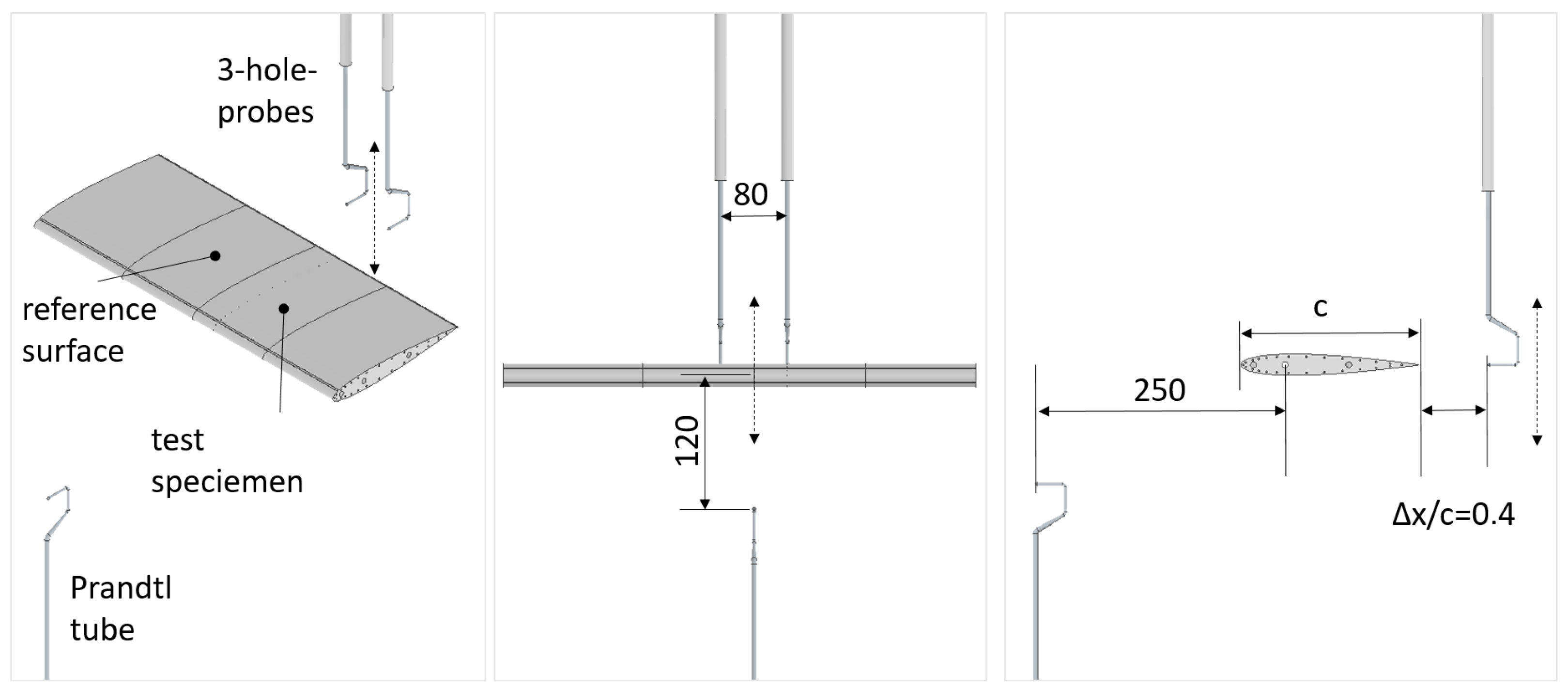
Aerodynamic assessment via wake surveys in a Göttingen-type wind tunnel.
Overall, the contribution of this study is twofold: it establishes the manufacturability of continuously adapted riblet structures on complex, curved surfaces and, by quantifying their enhanced drag reduction in wind-tunnel tests, provides the evidence base for practical deployment on turbomachinery blades.
2. Riblets: Drag Reduction by Passive Means
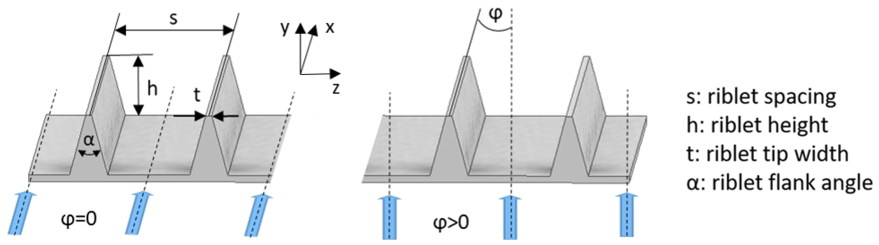
In the following remarks, only riblet structures with a trapezoidal groove shape are considered. The geometric parameters required to fully describe the geometry are summarized in
Figure 3 and include the riblet groove width
s, the tip width
t, the riblet height
h, the flank and misalignment anglea
and
, respectively.
Several numerical [
17,
18,
19] and experimental [
2,
20,
21] investigations have consistently proven that for turbulent flows the momentum transfer transverse to the main flow direction in the near-wall region is dominated by coherent vortex structures whose axes of rotation are oriented in the streamwise direction. The vortex structures appear as pairs of counter-rotating, quasi-streamwise structures forming elongated high- and low-speed streaks [
17,
19,
20]. In comparison to non-turbulent flows, the additional momentum transport increases the frictional losses. The drag-reducing mechanism of riblet surfaces can be attributed to an altering of the near-wall turbulence phenomena. According to [
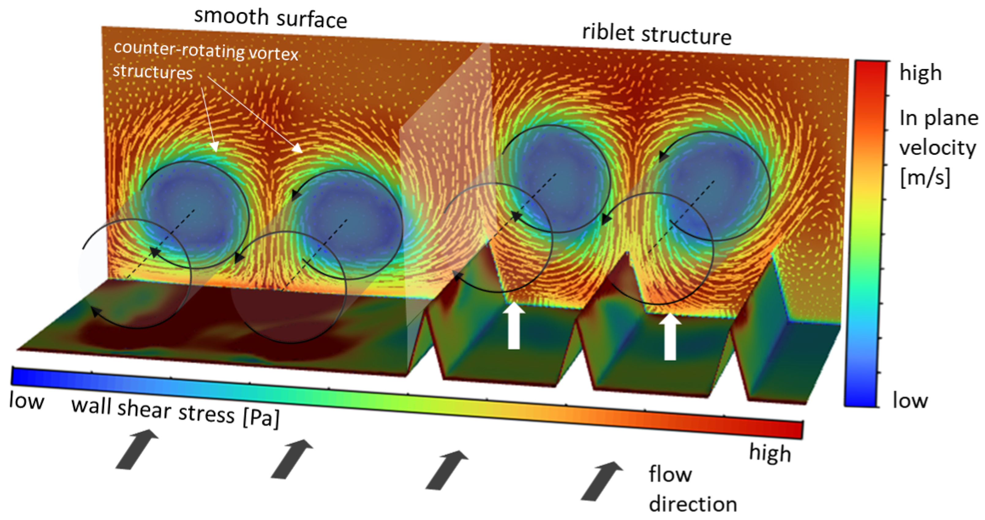
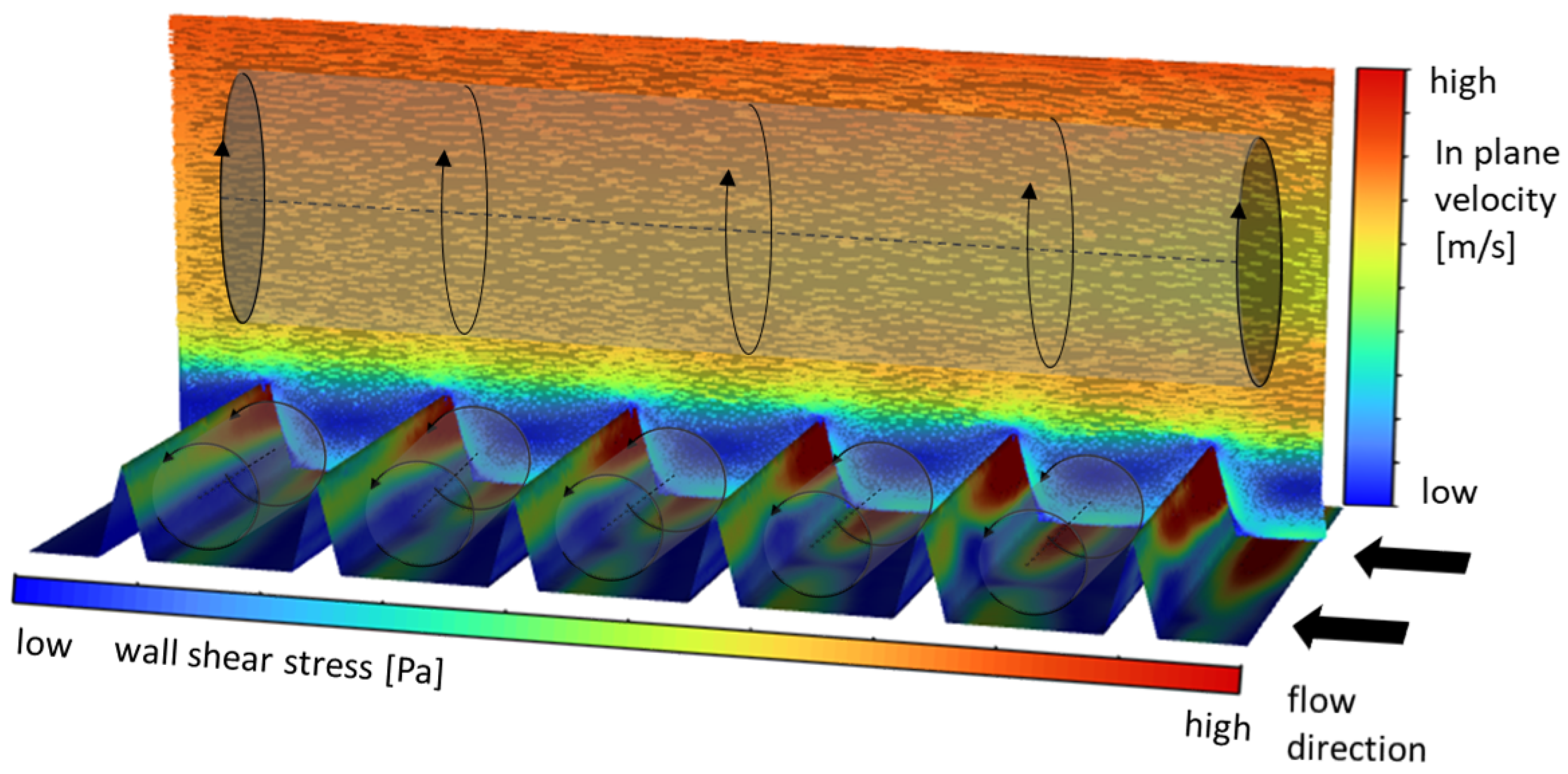
3], the application of longitudinal grooves impedes the crossflow component of the wall near vortices, which leads to them being raised. As the interaction of the vortex structures is now limited to the riblet tips, the total wetted surface area exposed to fluid of high-momentum is substantially reduced compared to the smooth surface as schematically illustrated in
Figure 4, hence resulting in lower viscous drag. In addition to reducing frictional losses, riblet structures can also diminish viscous-induced pressure losses. This effect arises from the modified velocity profile in the near-wall region, which leads to a reduction in the displacement thickness. Consequently, for applications such as turbomachinery where significant pressure losses occur, the overall drag reduction may clearly exceed the expected effectiveness estimated exclusively based on the wall shear stress reduction in the flat plate test scenario. However, when benchmarking riblet performance at least for the flat plate boundary layer the relative change in the wall shear stress compared to the smooth surface
is the standard metric.
2.1. Riblet Groove Width
In general a deviation from the optimal design specification will decrease the achievable drag reduction. In principle, this applies to all geometry parameters. Nevertheless, the following explanations will be limited to the influence of the riblet groove width
s and the misalignment angle
. For detailed information on the influence of the riblet tip width
t the reader may refer to [
6,
22]. Furthermore, the studies of [
6] give deeper insight into the impact of varying misalignment angles.
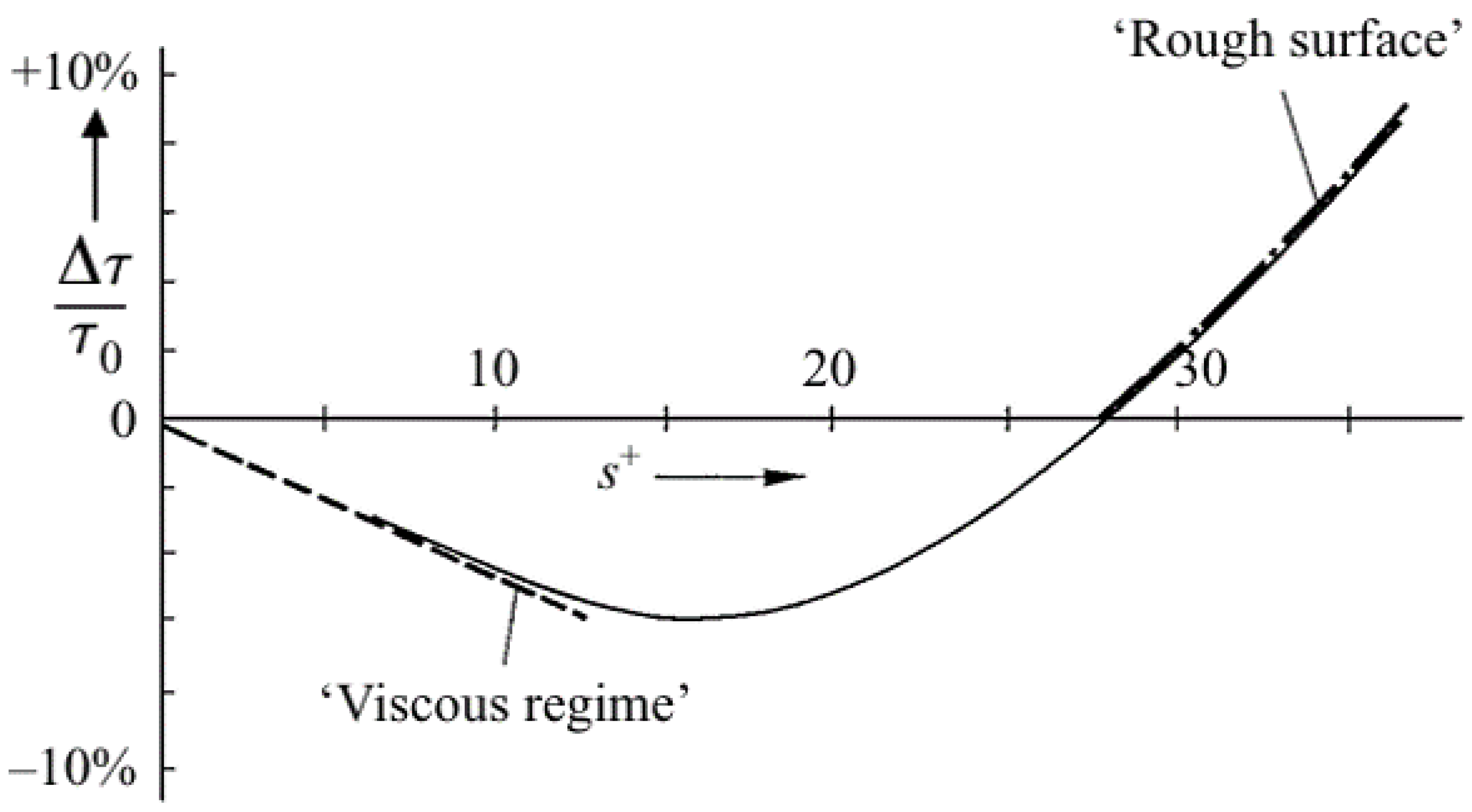
The selection of a suitable groove width
s is essential for riblet effectiveness (
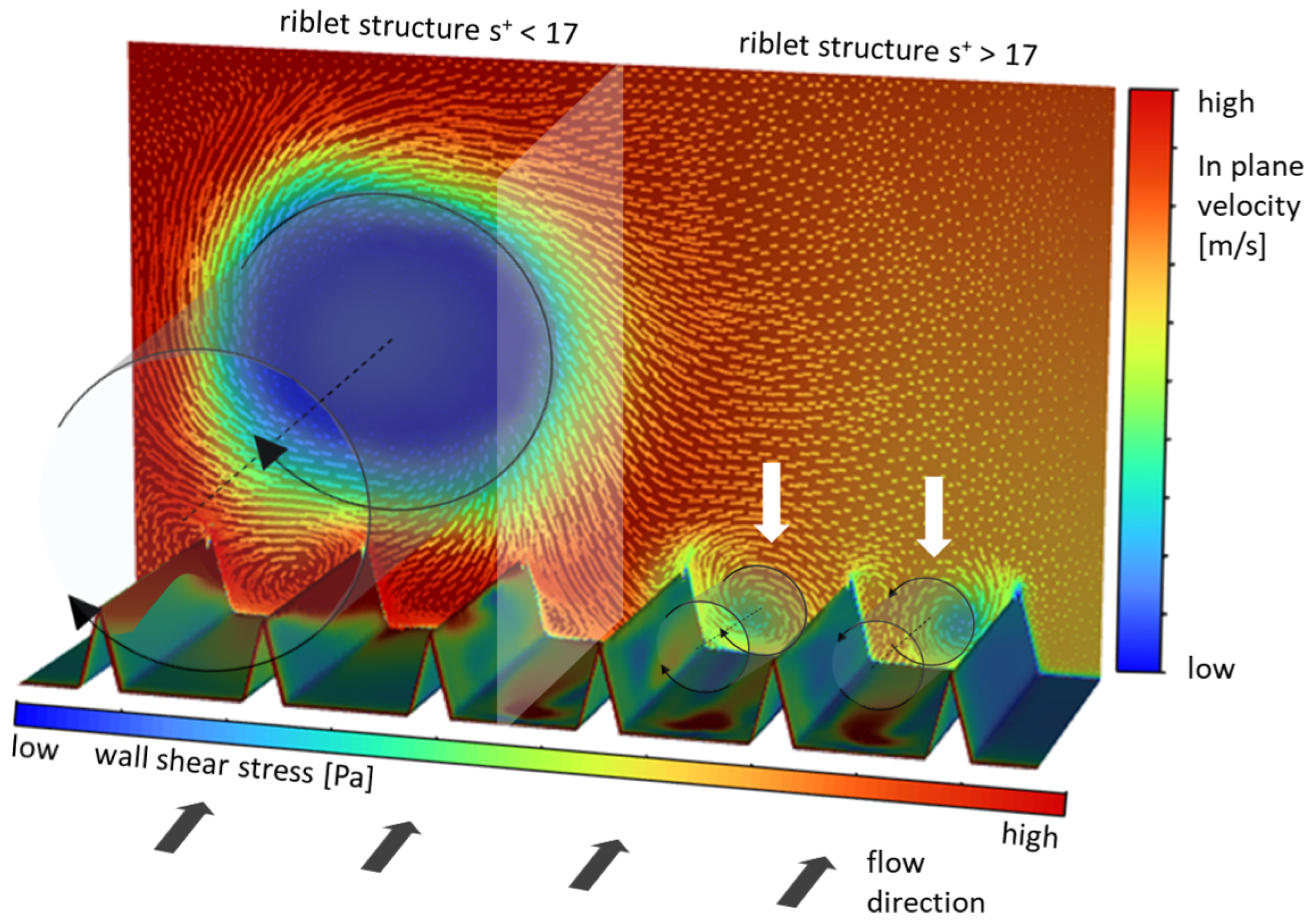
Figure 5). Only if the riblet spacing is slightly smaller than the characteristic diameter of the dominating vortices (
) will riblets prevent them from penetrating into the riblet valley (
). However, the size should not be selected too small, as otherwise the number of interactions with the riblet tips will increase statistically (see
Figure 6), reducing the possible drag reduction (
). Exceeding a critical limit (
), riblet structures protrude from the viscous sublayer and, comparable to surface roughness, increase the overall drag [
3].
On the other hand, if the riblet spacing exceeds the size of the vortex structure, these will increasingly invade into the valleys. As the surface area in contact with fluid of high momentum is enlarged, the drag-reducing potential is decreased (
). Because the optimal riblet spacing strongly depends on flow conditions, it has proven to be useful to express the riblet groove width in wall units
with the turbulent shear velocity
This normalization enables meaningful comparison across different facilities and Reynolds numbers, collapsing data onto a common scale. Consistent with literature, the maximum drag reduction for trapezoidal riblet structures on flat plates was obtained near a non-dimensional groove width of .
2.2. Misalignment
In contrast to the flat plate scenario most frequently used to study the drag-reducing mechanism of riblets, turbomachinery applications are characterized by strongly curved walls near streamlines. Therefore, the drag-reducing behavior of riblet structures under the influence of misalignment is of particular interest. First investigations on triangular-shaped riblets were carried out by [
5]. To simulate yawed flow, the riblet surfaces were continuously angled relative to the incoming flow direction. The investigations showed that riblet performance diminishes as the angle of misalignment increases. At higher yaw angles, secondary flows and cross-stream vortices become more prominent, leading to a less effective drag reduction (
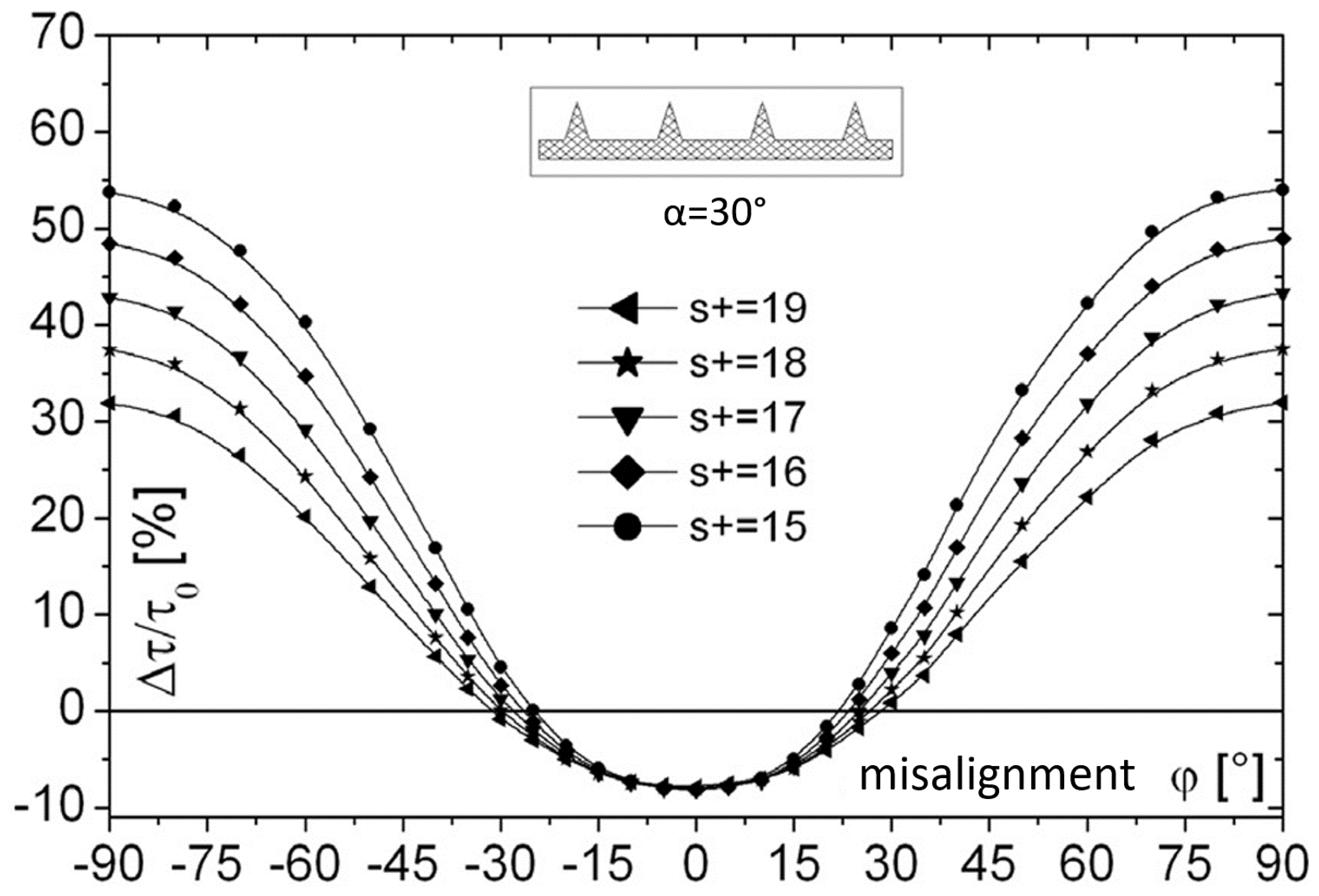
Figure 7).
The results of [
6] for trapezoidal-shaped riblets illustrated in
Figure 8 show a comparable behavior. As the misalignment angle increases, the achievable drag reduction continuously decreases. Moreover, exceeding a critical value, riblets behave similarly to surface roughness, increasing the aerodynamic losses. This particular influence has subsequently been demonstrated on airfoils, swept wing applications and wing-bodies as summarized by [
23]. Comparable, the benefits associated with riblet application gradually diminish when riblet structures are not aligned with the near-wall flow.
3. Turbomachinery Application
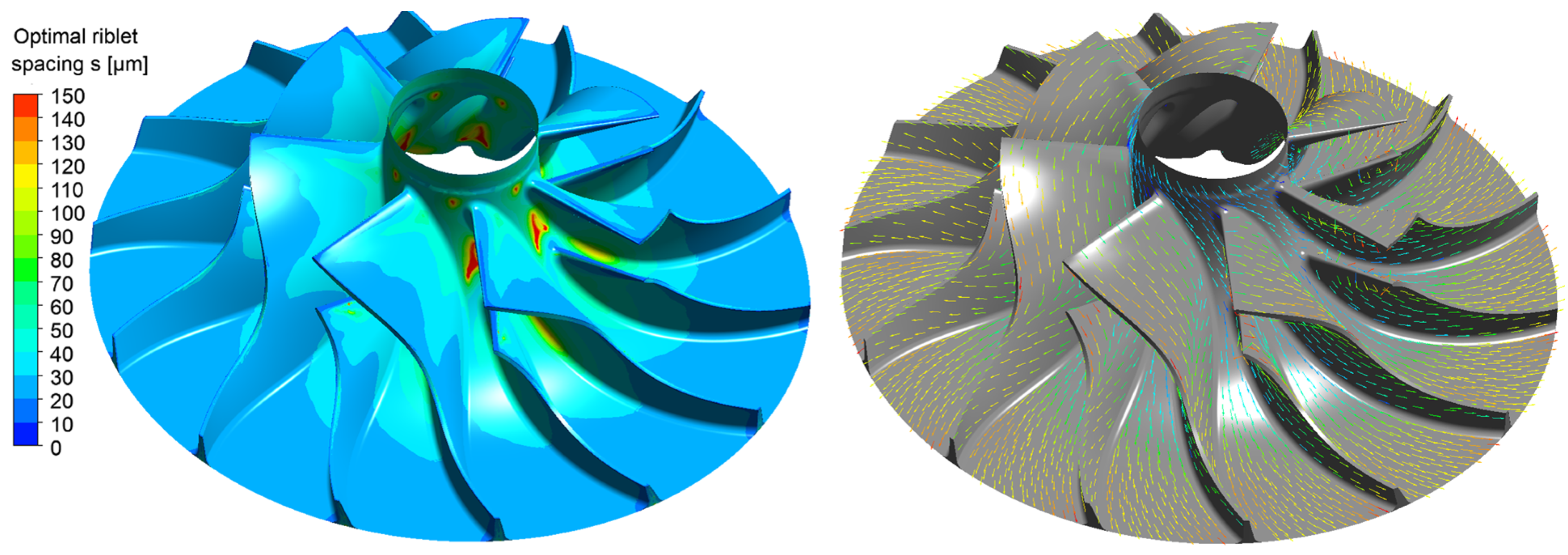
In turbomachinery, where flow fields are highly three-dimensional, strongly unsteady, and subject to significant spatial variations, conventional riblet structures with fixed dimensions face fundamental limitations. Their geometric parameters, particularly the groove width and the orientation will not correspond to the optimum value, which significantly diminishes the achievable drag reduction. This effect is illustrated in
Figure 9, which shows the distribution of the optimal non-dimensional riblet spacing
s and local streamline orientation across the blade surface of a centrifugal compressor rotor. The data were obtained from Reynolds-Averaged Navier–Stokes (RANS) simulations employing a sliding-mesh approach as described by [
24]. The investigated stage, provided by IAV GmbH, Gifhorn, Germany, operates at a design speed of
n = 67,577 rpm with an impeller diameter of
mm and achieves a pressure ratio of approximately
under design conditions. The numerical results were validated against experimental data, confirming the predictive accuracy of the model. As shown, the optimal riblet spacing varies by more than a factor of 3 between the leading-edge region and the blade outlet, while the local streamline angle exhibits deviations exceeding
along the blade surface. Such pronounced variability implies that a riblet geometry optimized for one region of the flow field will be substantially misaligned in others, resulting in a significant loss of drag reduction potential. Consequently, the performance of riblet-based passive flow control in turbomachinery is fundamentally constrained by current manufacturing limitations. The ability to fabricate surface structures with spatially resolved variations in spacing and orientation is essential for aligning riblet geometry with the local flow field, thereby enabling the full exploitation of their drag-reducing potential in the highly three-dimensional boundary layers of rotating machines.
4. The NACA0012 Airfoil
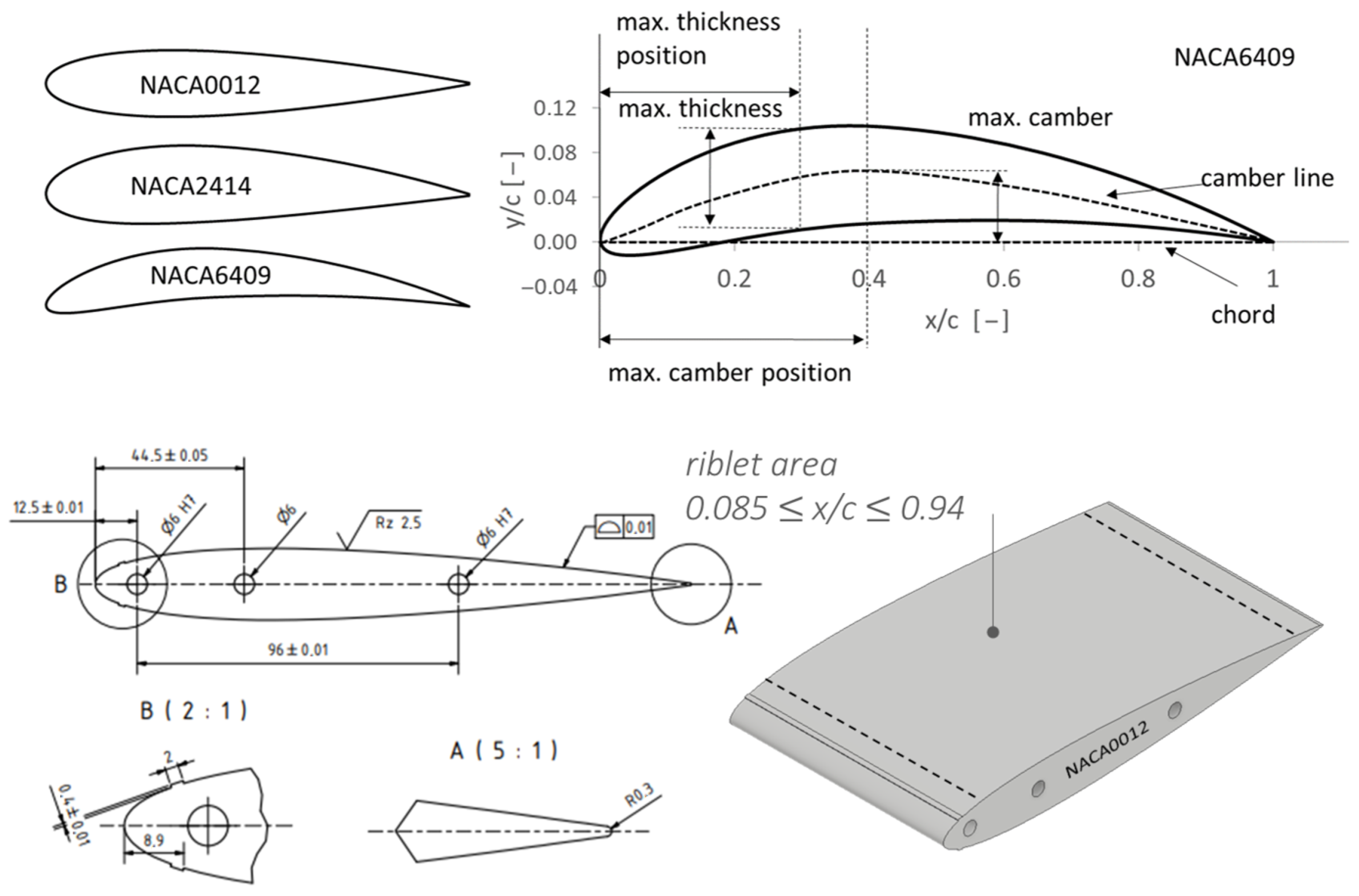
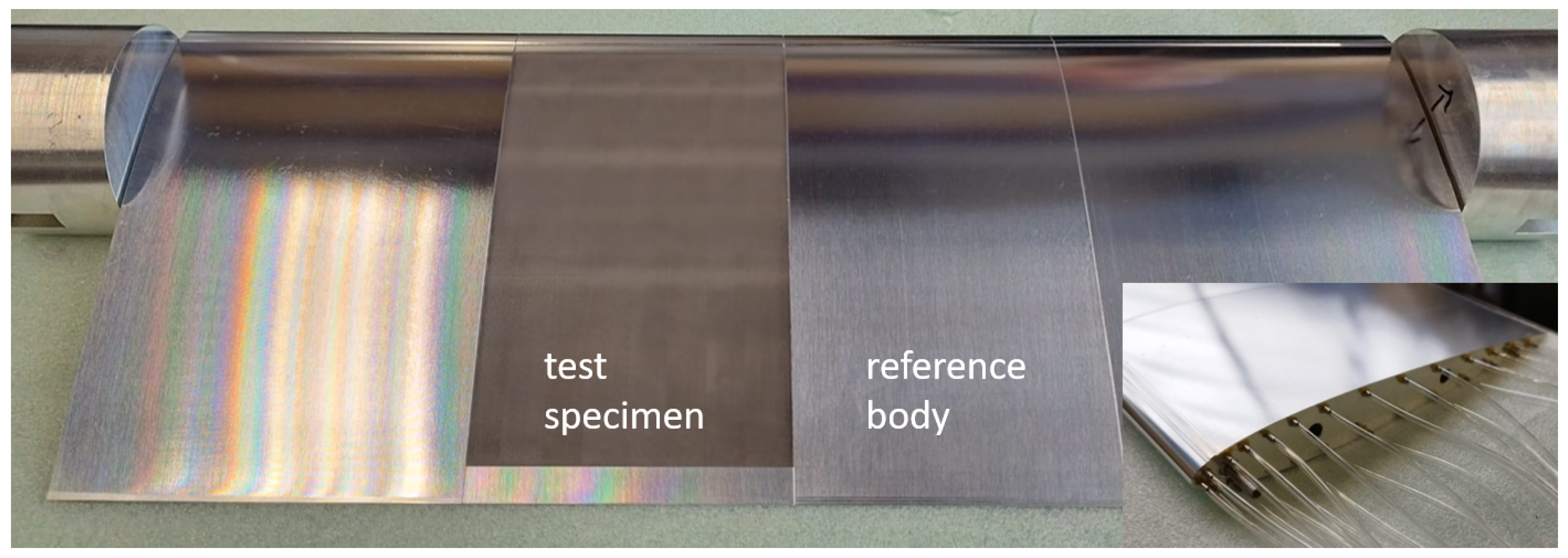
Within this study the NACA0012 airfoil was selected as a reference geometry for the fundamental investigations due to several advantageous characteristics. First, it is one of the most extensively studied airfoil profiles in aerodynamics, with a large body of validated numerical and experimental data available in the literature. This provides a reliable basis for benchmarking and validating new experimental approaches, including surface modification techniques such as tailored riblets. Moreover, the two-dimensional nature of the flow around the NACA0012 results in streamlines that remain essentially parallel to the airfoil surface along the chord. As a consequence, riblet structures with a fixed orientation are not subject to misalignment effects, in contrast to the highly three-dimensional flow fields present in turbomachinery components. This characteristic makes the NACA0012 an ideal test case for isolating the influence of riblet spacing as a key design parameter, since its aerodynamic impact can be investigated independently of orientation-related effects. Such a configuration enables a fundamental assessment of how groove width affects drag reduction in both accelerated and decelerated boundary-layer regions under well-defined and reproducible conditions. Another important consideration is the practical aspect of experimental implementation: the NACA0012 can be readily tested in standard low-speed wind tunnels, and the use of existing experimental infrastructure enables controlled investigations under highly reproducible conditions. The NACA0012 airfoil is a two-dimensional cross-section developed by the National Advisory Committee for Aeronautics (NACA). Its numbering system characterizes the airfoil’s geometry, which is essential for its aerodynamic properties. The NACA0012 is a symmetric airfoil with no camber and a maximum thickness of
located at
of the chord length. For the experimental investigations, a NACA0012 airfoil with a chord length of 178 mm was used, corresponding to a Reynolds number of approximately
, based on the chord length. Riblets were applied over the surface from
, covering
of the surface. To ensure a fully developed turbulent boundary layer at the given Reynolds number, flow transition was triggered near the leading edge using a tripping hazard with a total height of
mm (
Figure 10).
5. Riblet Fabrication
In recent decades, various manufacturing techniques have been explored for the fabrication of riblet structures, including milling, grinding [
25,
26], rolling [
27,
28], extrusion and embossing [
29], as well as lithography-based methods [
30]. Vinyl adhesive riblet sheets produced by The 3M Company have been widely used, as they combine high precision with the capability of large-scale production. Each of these approaches mentioned offers specific advantages and disadvantages with respect to factors such as cost, achievable dimensions, durability, substrate material, and thermal and chemical compatibility. The work of [
31] provides a good overview. However, a common limitation of all mentioned methods is their insufficient flexibility in producing variable riblets in terms of size and orientation, a prerequisite for the effective implementation in turbomachinery applications.
To overcome this limitation, a collaborative research initiative between the Jade University of Applied Sciences and the Laserinstitut Hochschule Mittweida (LHM), funded by the German Federal Ministry of Education and Research (BMBF), has been ongoing since 2017. Within this framework, a novel high-rate laser structuring technology has been developed that, for the first time, enables the fabrication of riblet structures with dimensions and orientation changing continuously. In the following, the high-rate laser processing is briefly described. For more detailed information, the reader may refer to [
32,
33,
34,
35,
36,
37].
5.1. Laser-Based Riblet Fabrication
The use of laser engraving technologies for precise production of micro-scale riblet structures with constant dimensions has already been demonstrated [
38,
39,
40,
41,
42] and investigated in more detail by considering the effect of laser processing conditions on riblet formation by [
36,
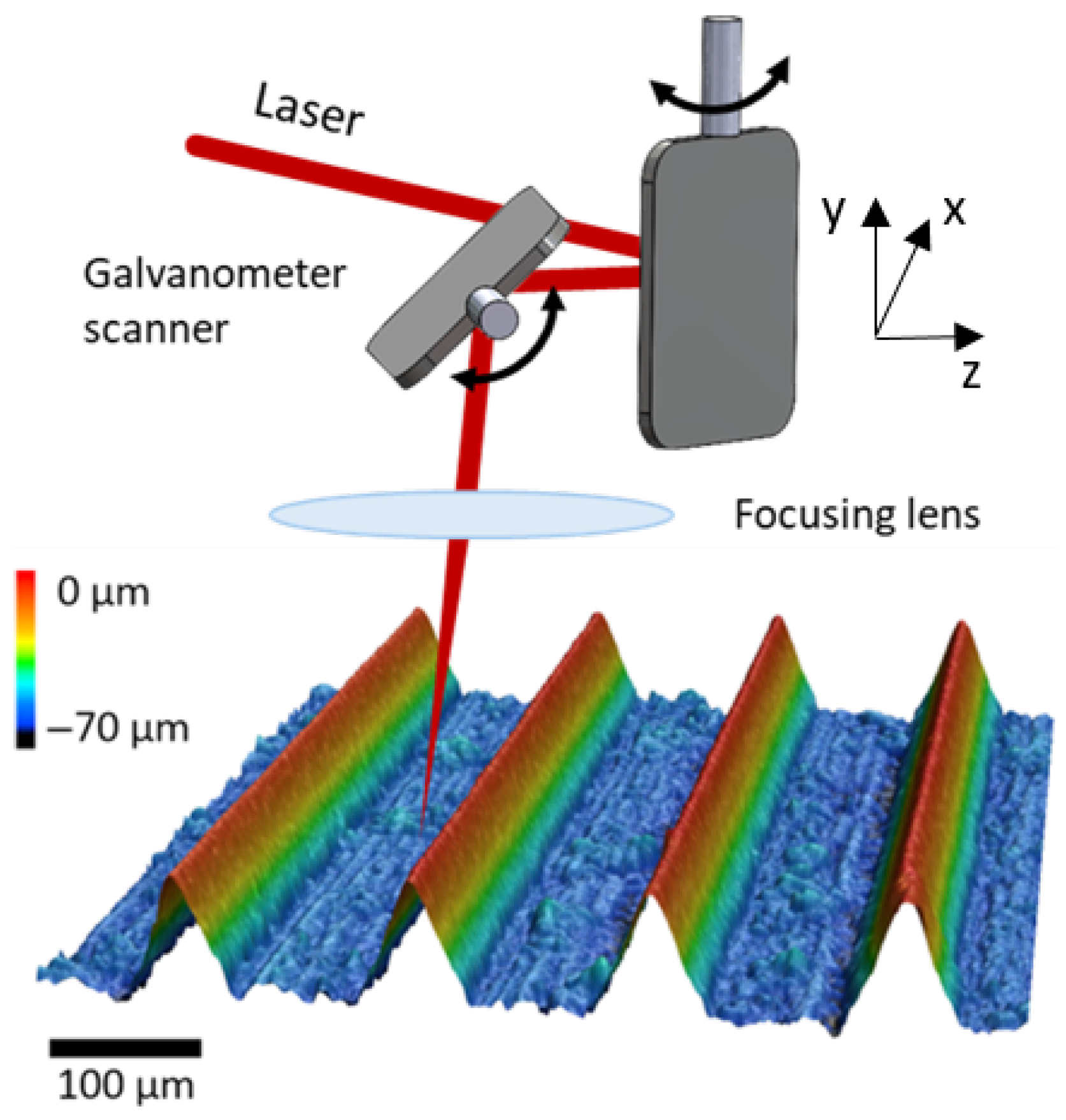
37] in recent years. As a fundamentally subtractive process, laser fabrication ablates material to create recessed grooves within the base material. In particular, the use of high-intense ultrashort pulsed laser radiation allows high precision and great flexibility regarding microscopic dimensions and spatial orientation of riblets largely independent of the base substrate material, which is the basic precondition to produce constant or continuously adapted riblets. Moreover, the extremely short pulse duration in the femtosecond range leads to a highly localized energy deposition and significantly reduces the overall heat input into the base material, preventing unwanted thermal effects. This ensures high surface quality and preserves the functional geometry of the riblet structure. The localized removal of material to form riblet grooves is typically achieved by scanning the tightly focused laser beam over the workpiece surface using galvanometer-based mirror systems or high-speed polygon scanner units. The principle procedure is illustrated in
Figure 11. Galvanometer scanners enable precise, point-by-point beam positioning with high spatial resolution, which is essential for accurately reproducing complex riblet geometries. Polygon scanners, in contrast, allow for extremely high scanning speeds and thus significantly increase processing throughput, especially for large-area structuring. These beam delivery strategies are key to combining the intrinsic precision of ultrashort pulse laser processing with the scalability required for industrial riblet fabrication. These characteristics represent the major advantage of ultrashort pulse lasers (USPL) over standard micromachining processes in riblet profiling, such as grinding, embossing or micro milling.
Within this study, an ultrashort pulsed laser system (UFFL100, Active Fiber Systems GmbH, Jena, Germany) was combined with a galvanometer scanner (ExcelliSCAN14, SCANLAB GmbH, Puchheim, Germany). The key parameter settings of the laser machining setup are listed in
Table 1.
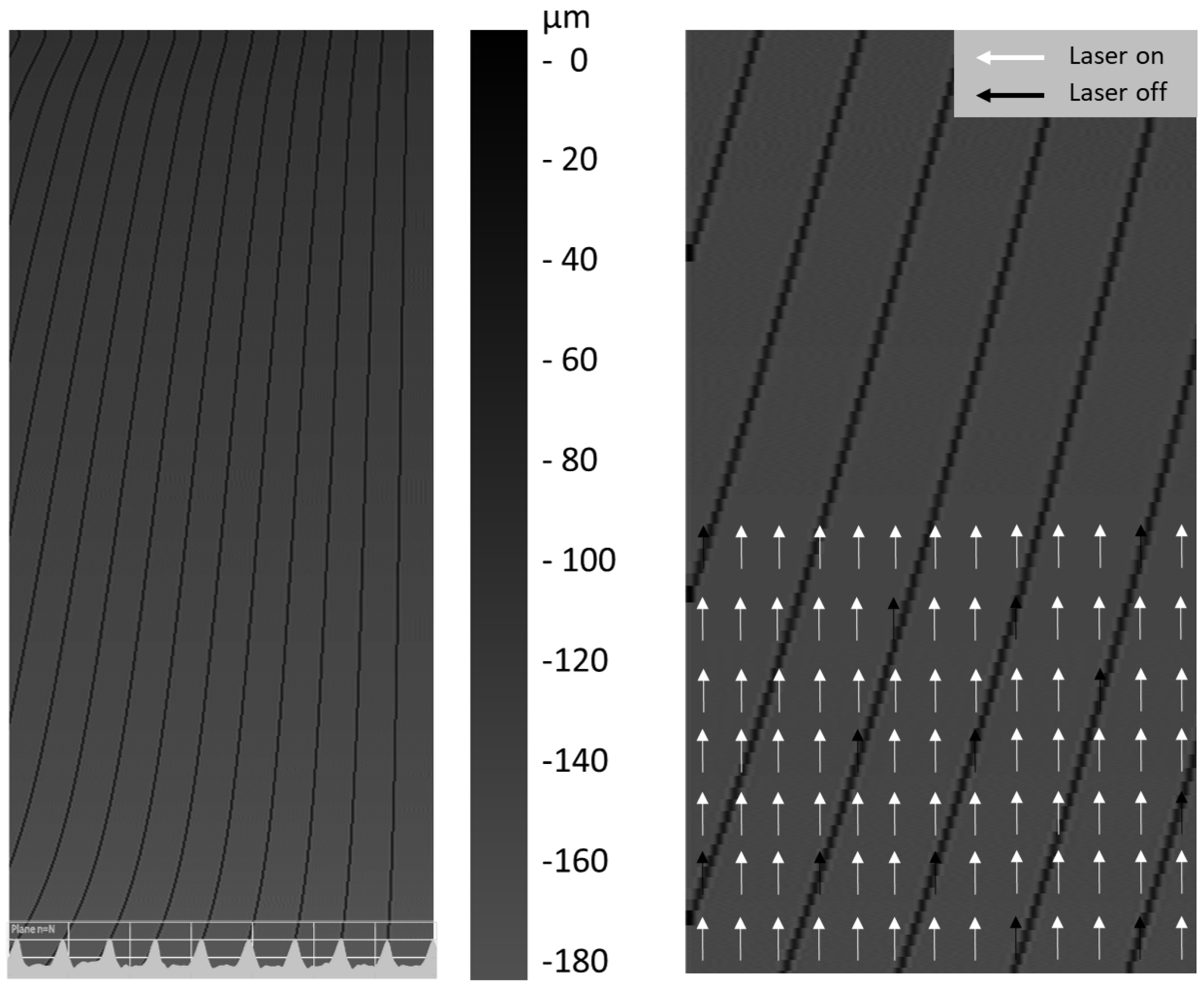
The entire riblet-structured surface to be laser machined was discretized with a lateral pixel resolution of 5 µm and converted into an 8-bit gray-scale-coded depth map (bitmap). The resulting bitmap was sliced into layers of predefined thickness and converted into a list of vectors arranged parallel to each other. The lateral distance between adjacent vectors was the same as the pixel resolution. The laser machining regime was “on-the-fly”, where the vectors marked the areas in which the laser is active or inactive,
Figure 12.
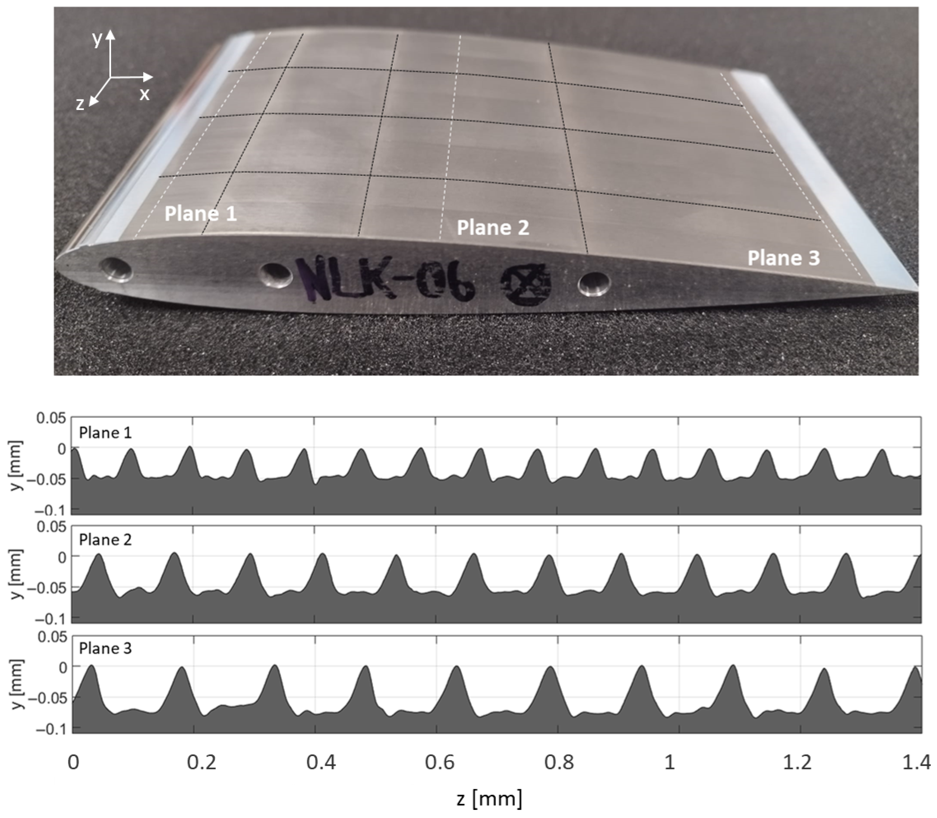
In the case of the NACA0012 airfoil, it was necessary to split up the total area of the NACA0012 airfoil into several sub-areas (
Figure 13 top) because of the limited size of the laser scanning field and the curved shape of the airfoil surface. The segmentation of the surface into smaller processing fields was essential to compensate for the geometric curvature and ensure that the laser spot remained precisely focused on the target surface throughout the process. The sub-areas were processed sequentially, with the NACA0012 profile rotated in such a way that the laser beam always irradiated perpendicularly onto the local surface. An excerpts of the manufactured riblet structures close to the leading edge and the trailing edge, as well as in the mid-chord region of the profile, are shown in the bottom part of
Figure 13.
5.2. Topographical Analysis
For the geometric evaluation of the laser-fabricated riblet structures, the surface topography was characterized using a machine-integrated confocal point sensor system (KF3 tele, OPM). This optical, non-contact measurement technique is particularly well suited for highly precise characterization of microstructured surfaces, as it allows for accurate detection of both lateral and vertical geometric features without influencing the surface condition. The nominal spatial resolution of the sensor is 2 μm in the lateral direction and 0.02 μm in the axial direction, which is sufficient to resolve even fine details of the riblet tips and grooves. To capture the entire laser-processed area, a grid of equidistant measurement lines with a spacing of 2 mm was applied across the surface. This scanning strategy ensured comprehensive coverage of the structured region while keeping the measurement time at a practical level. The resulting high-resolution 3D surface data provided detailed information on all key riblet geometrical parameters enabling a thorough comparison with the nominal design geometry. Moreover, the topography data were used to assess the uniformity and reproducibility of the laser structuring process across the curved airfoil surface. Deviations from the nominal dimensions provided insight into potential influences of laser parameters, focus position, and scanning strategy on the resulting structure quality. This geometric characterization formed the basis for predicting the aerodynamic effectiveness of the riblet surfaces, as discussed in
Section 8, and served as a key input for subsequent performance evaluations in terms of drag reduction potential and surface quality.
5.3. Possibilities and Limitations
The laser process allows the dimensions of riblets as well as their geometric orientation to be continuously adjusted. In addition, very hard or high-temperature-resistant materials can usually be processed as well. The steady progress in the development of new high-power USP laser systems allows upscaling the processing rates for achieving industrially relevant throughputs. This enables the use of laser-based riblet technology, particularly in the field of turbomachinery. However, there are also the following technological limitations that should be considered in laser-based profiling:
The surfaces to be structured must be freely accessible to the laser beam.
The smaller the dimensions of the riblets to be produced, the sharper the laser beam must be focused.
The production effort increases significantly for decreasing riblet groove widths.
Currently trapezoid-shaped riblets with a groove width in the range of μm are technically feasible; smaller riblets are possible, whereby the riblet geometry increasingly changes from trapezoidal to more sinusoidal.
6. Riblet Application
Based on numerical simulations of the smooth test surface, ideal riblet structures with both constant and continuously adapted dimensions were designed, manufactured, and subsequently measured using optical methods. From these results, the geometric parameters of laser-manufactured, non-ideal riblet structures can be determined locally, enabling a comparison with the nominal design geometry and the prediction of riblet effectiveness. The following sections offer a detailed insight into the riblet design process and structural analysis.
Riblet Design
The wall shear stress reduction in trapezoidal-shaped riblet structures can generally be expressed as a function of the riblet groove width
s, the height-to-spacing and tip-width-to-spacing ratios
and
, the flank angle
, as well as the misalignment angle
If only ideal riblet structures are considered, meaning riblet structures whose tip width
t, height
h and flank angle
correspond to the optimum specifications of
,
and
, then Equation (
4) reduces to
The relationship between wall shear stress reduction and both parameters, the groove width
s and misalignment
has been thoroughly investigated and is well documented in experimental studies, providing a reliable basis for predictive modeling of riblet performance [
6,
43].
Further considering the flow around an extruded two-dimensional profile section, it is assumed that the streamlines have no transverse components in the spanwise direction. For riblet structures with constant dimensions, this implies that no misalignment occurs. Consequently, the number of geometric parameters governing the wall shear stress reduction is reduced to a single variable, the riblet groove width
s
or its non-dimensional value
. For trapezoidal-shaped riblet structures, the maximum drag reduction is observed at a non-dimensional riblet spacing of
. The groove width can be approximated using the relationship
whereby the shear velocity
is defined as
Accordingly, knowing the wall shear stress distribution of the smooth reference surface
(7), a suitable groove width can be chosen. To compute the optimal groove width for riblets with constant dimensions, the approach described by [
14] is followed. The basic procedure can be summarized as follows:
Groove width variation and computation of the local non-dimensional value .
Forecast of the wall stress reduction based on empirical data .
Integration of the resulting wall shear stress distribution .
Determination of the groove width that minimizes .
It should be noted that the calculated groove width, even if theoretically optimal, is only ideally adapted to the local flow conditions at a single point on the airfoil surface, since these conditions vary significantly along the profile. This fact represents a fundamental limitation for the application of constant riblet structures in technically relevant environments.
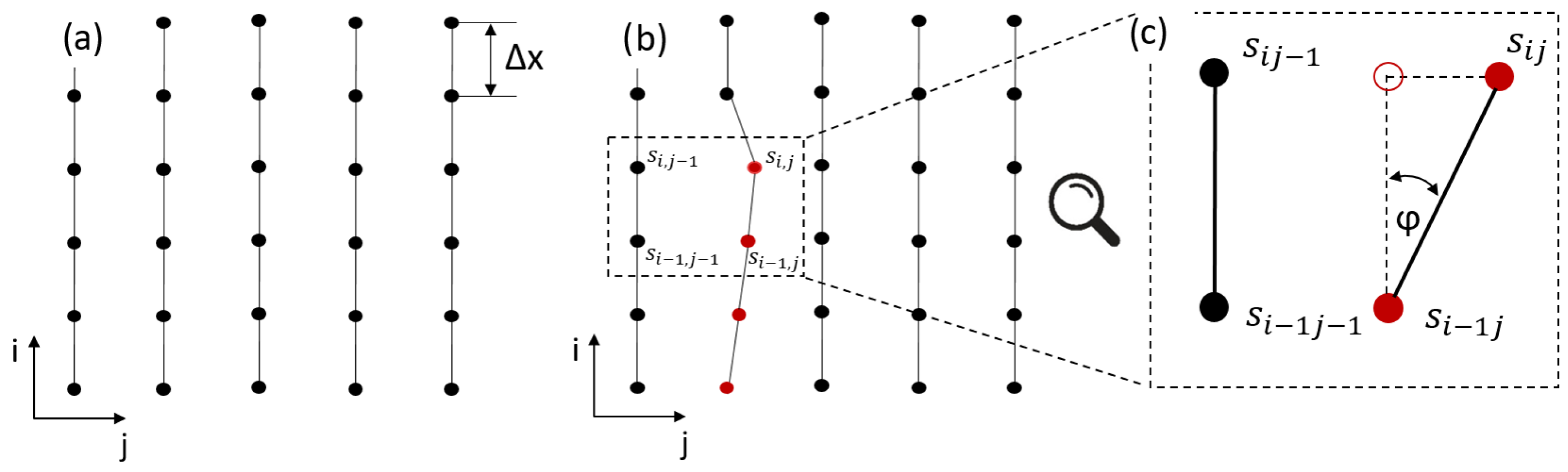
The design of riblet structures that are continuously adapted to the local flow conditions basically follows the same procedure, with the exception that the computation is performed locally. For this purpose, the riblet structure is discretized into a series of supporting points that represent the riblet tips along the flow axis. The calculation of the optimal groove width is performed sequentially for each individual supporting point (
Figure 14).
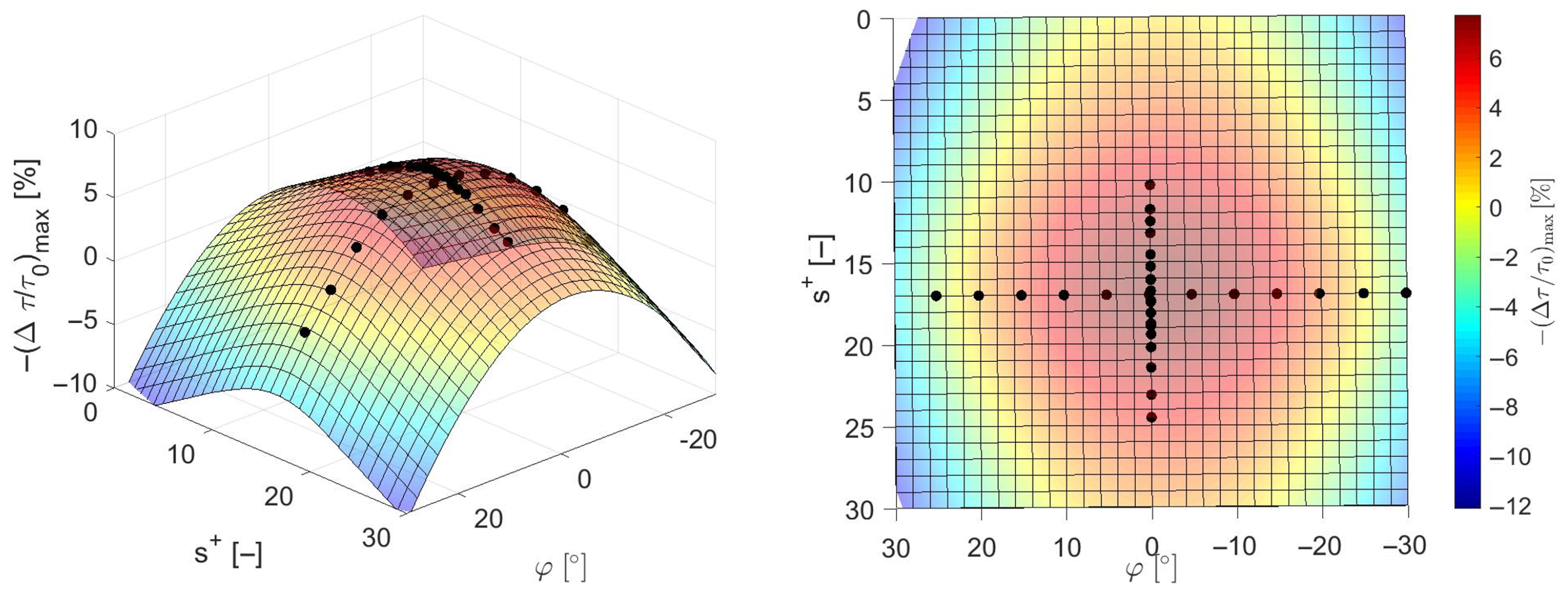
The essential difference is that, in this calculation, the influence of a flow misalignment must be taken into account as a widening or narrowing of the groove width inevitably increases the yaw angle. Therefore, the dependency used to predict riblet effectiveness for constant riblet structures given by Equation (
6) must be replaced by Equation (
5). For this purpose, the extended dependency shown in
Figure 15, which is derived from the empirical data reported by [
6], is employed to estimate the wall shear stress reduction. In contrast to the conventional approach, which considers only the influence of a single parameter, this extended formulation accounts for the combined effects of both groove width and flow misalignment. The individual influence of each parameter is determined by evaluating the relative reduction in drag-reduction potential resulting from its deviation from the respective optimum. These relative losses are then summed to obtain the cumulative decrease in wall shear stress reduction achievable under the given conditions.
7. Numerical Approach
The local wall shear stress distribution was obtained by solving the steady Reynolds-Averaged Navier–Stokes (RANS) equations using the finite-volume solver Ansys Fluent. The two-dimensional simulations were conducted with the shear stress transport (SST) turbulence model in a low-Reynolds-number, wall-resolving formulation (
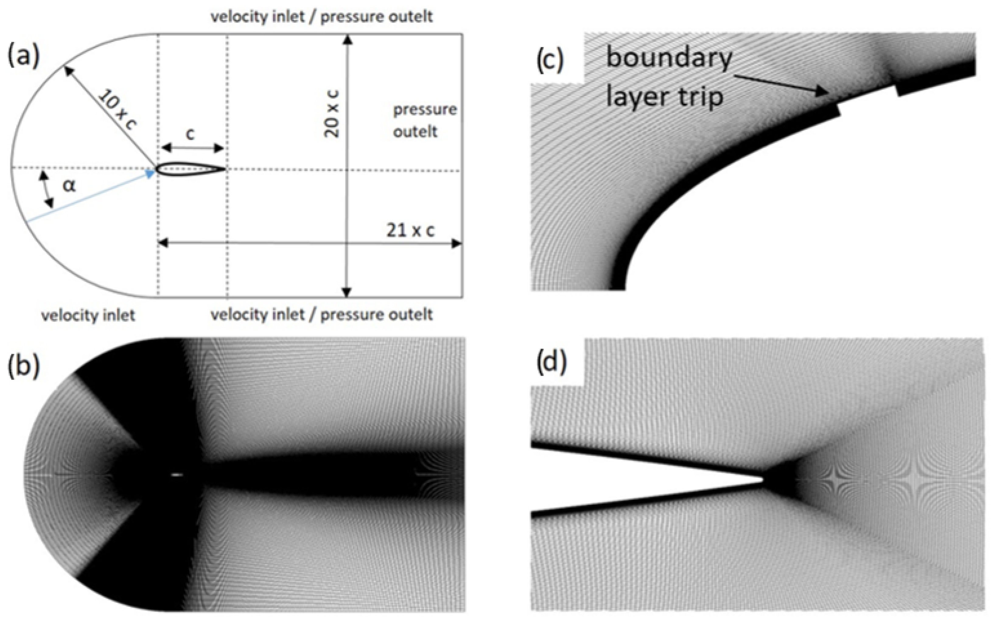
) to accurately resolve the near-wall flow behavior and capture the wall shear stress gradients with high fidelity. The governing equations were discretized using a second-order upwind scheme for the convective fluxes in both the momentum and turbulence transport equations, while pressure–velocity coupling was handled via the SIMPLE algorithm. The computational domain was designed to represent a mid-span section of the airfoil under zero angle of attack, with sufficiently large inflow and outflow extensions to minimize boundary condition effects. No-slip and adiabatic conditions were imposed on the airfoil surface, while uniform velocity and turbulence were prescribed at the inlet. The outlet was treated with a fixed static pressure condition. Far-field boundaries were located sufficiently far from the profile to avoid numerical interference. A high-quality, structured C-type mesh was generated using ICEM CFD, with local refinement in the near-wall region to satisfy the
criterion (
Figure 16). The mesh was progressively refined following the Richardson extrapolation method, and grid independence was verified by comparing drag coefficients and surface shear stress distributions across multiple grid densities. Based on a Taylor series extrapolation, the estimated discretization error for the drag coefficient
was below
, ensuring numerical reliability. The resulting distribution of local wall shear stress, together with the corresponding optimal riblet spacing computed according to Equation (
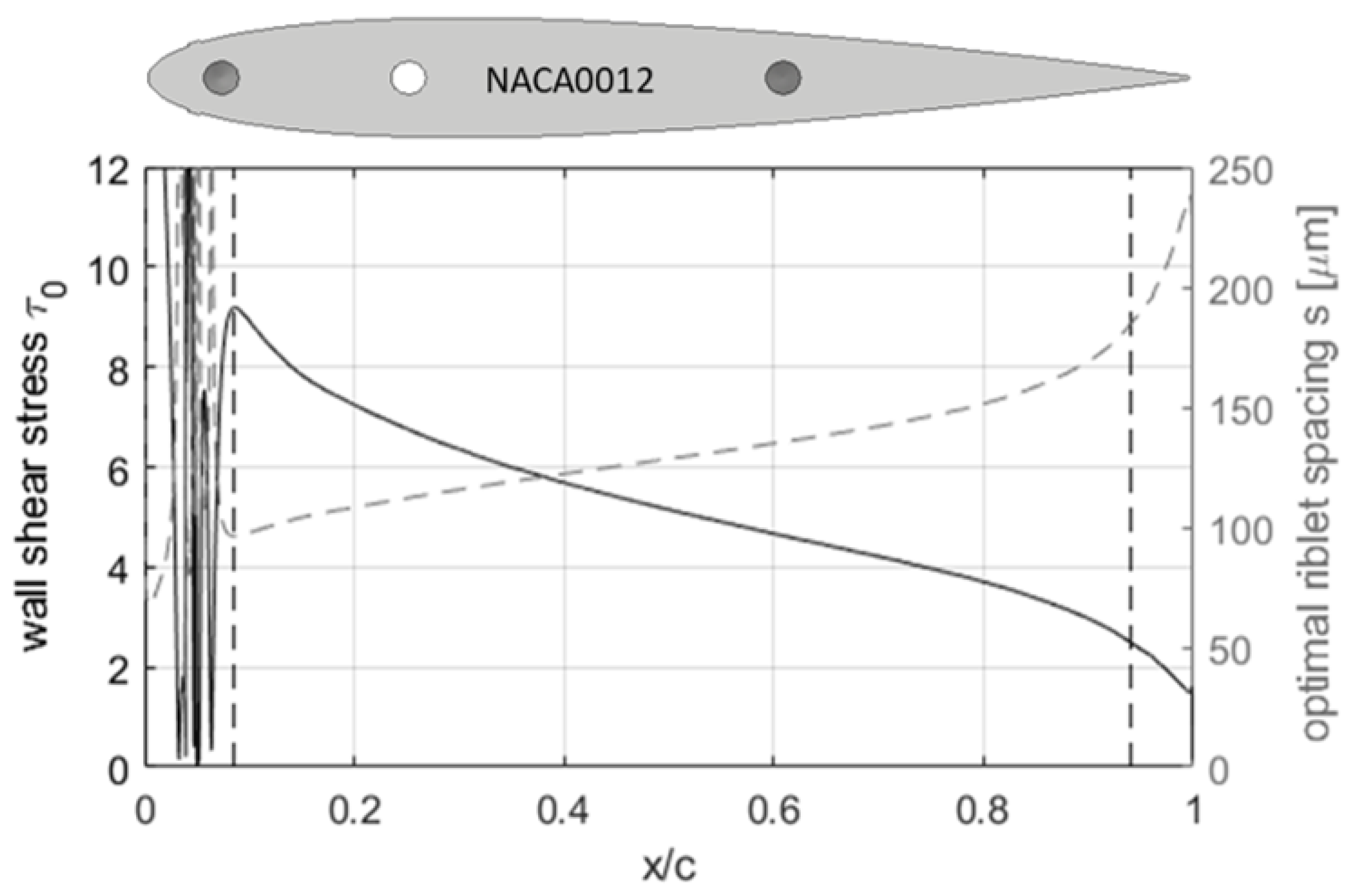
7) under zero angle of attack, is presented in
Figure 17. These results form the basis for the riblet design process outlined and serve as an essential input for the subsequent analysis of riblet adaptation strategies.
8. Geometrical Analysis
The topographic data obtained through the confocal point sensor system serve as the basis for the subsequent geometrical analysis. Using this information, the characteristic riblet dimensions are determined locally along the surface.
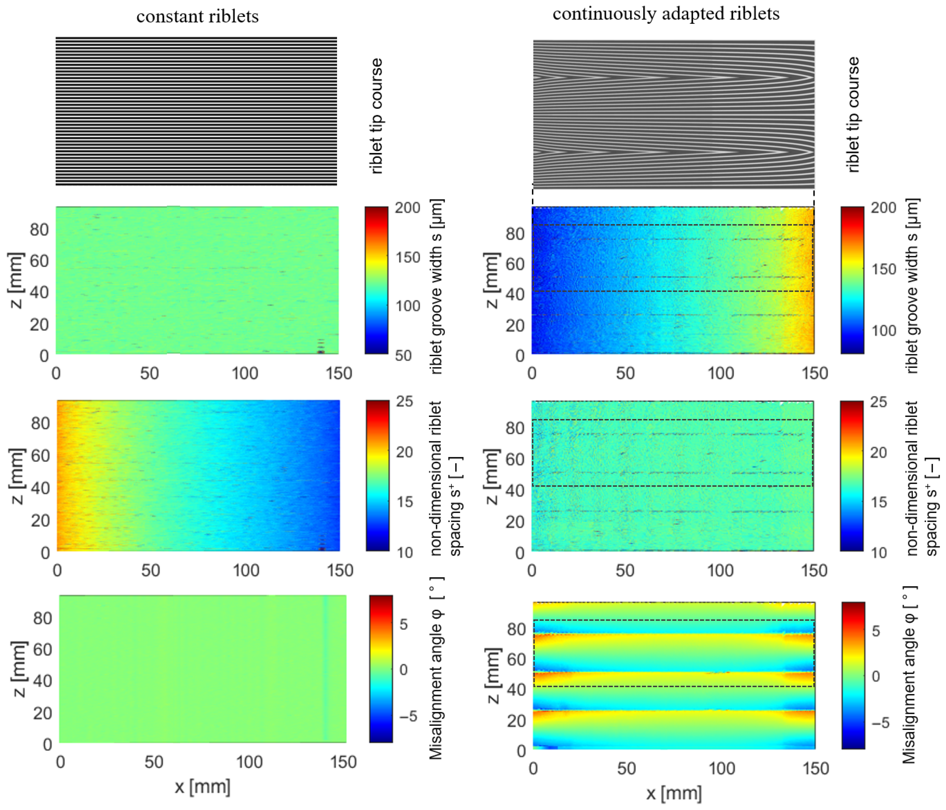
Figure 18 presents the results for both constant and continuously adapted riblet geometries on the suction side of the NACA0012 airfoil. In addition, an excerpt of the riblet tip trajectory is shown to provide a clearer understanding of the spatial evolution of the structure. For better visualization, the riblet geometry is scaled by a factor of 30. The results indicate that by adapting the riblet geometry to the local flow field, the optimal non-dimensional spacing of
can be consistently maintained across the surface. However, the continuous expansion of the riblet groove width progressively increases the misalignment in the spanwise direction, particularly in regions with high flow gradients. Therefore, to minimize this impact, the structuring process was aborted once a critical threshold was exceeded, and instead the resulting structure was arranged consecutively. The procedure outlined enables an overall higher wall shear stress reduction compared to riblets with constant dimensions. This becomes evident from
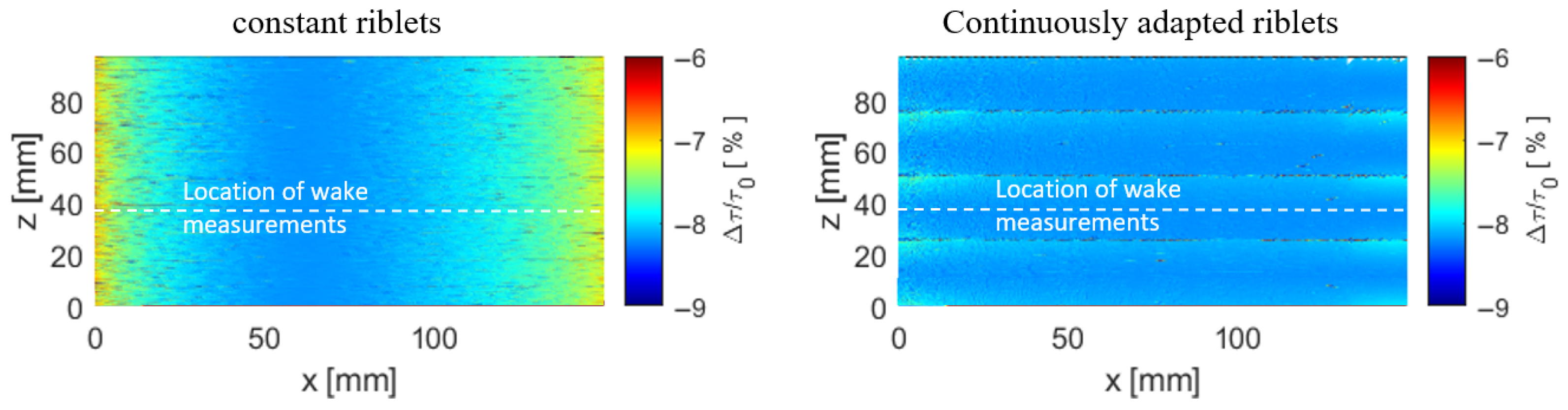
Figure 19, which shows the predicted wall shear stress reduction based on the approximation for ideal trapezoidal-shaped riblet structures illustrated in
Figure 15. For this purpose, the empirical model originally developed for riblet design is applied inversely.
10. Results
The manufactured riblets were specifically designed to match the flow conditions on the NACA0012 airfoil at zero angle of attack (
) at a chord length-based Reynolds number of
. Consequently, the results presented here are restricted to the evaluation under these design conditions. Thereby, the one-sided and two-sided riblet applications are analyzes separately. Apart from enabling a more detailed analysis of the aerodynamic effects on each surface, this approach also provides an important methodological advantage. Since the same measurement setup and instrumentation are used in both cases, a comparison between the two configurations serves as a consistency check of the experimental data. If the drag reduction observed for the two-sided application corresponds approximately to twice the value measured for the one-sided case on the symmetrical airfoil, this confirms the validity of the measurement technique and ensures that the results are not affected by systematic errors or setup-related asymmetries. To establish a reference for the subsequent analysis, the results obtained for riblets with constant dimensions are first considered and compared with findings from the literature. In particular, the studies of [
7,
8], who also performed wake measurements on subsonic airfoils equipped with riblet structures, are summarized. In contrast to the present work, however, these investigations employed riblets with a triangular cross-sectional geometry applied in the form of adhesive vinyl sheets. Subsequently, the results obtained for continuously adapted riblets are compared. However, before this comparison can be made, the numerical model must first be validated by comparing the simulation results with the experimental data. This step ensures that the numerical approach accurately captures the relevant physical mechanisms and provides a reliable basis for evaluating riblet performance.
10.1. Model Validation
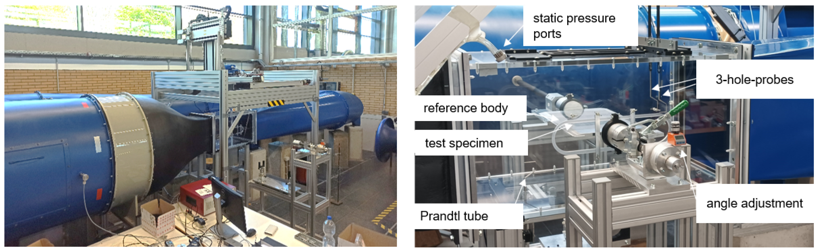
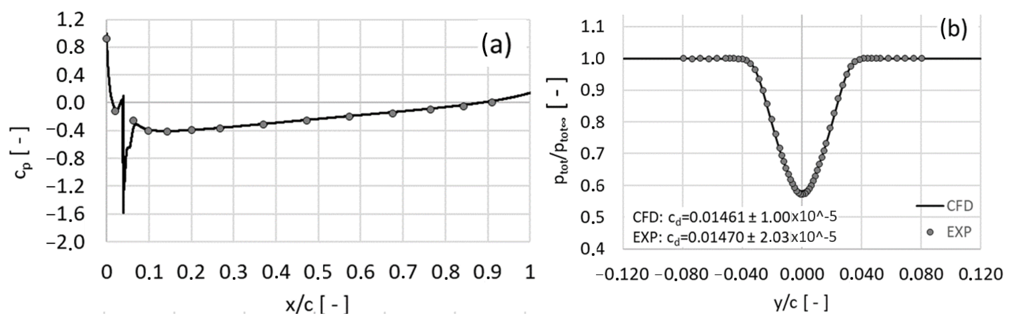
The Reynolds-Averaged Navier–Stokes (RANS) equations can only approximate the physical flow field, as they rely on turbulence modeling assumptions and empirical closure relations. Consequently, validation of the numerical results against experimental data is essential to ensure that the simulations capture the dominant flow phenomena with sufficient accuracy. Ideally, the wall shear stress would serve as the primary validation quantity, since it directly governs the riblet design process and determines the achievable drag reduction. However, due to current experimental limitations in resolving wall shear stress distributions on curved surfaces with adequate spatial resolution, indirect but physically relevant quantities are used instead. Specifically, the static surface pressure distribution along the airfoil and the total pressure distribution in the wake were measured and compared to their numerical counterparts. These quantities are closely related to the pressure and viscous drag components and thus provide a meaningful basis for validating the predictive accuracy of the numerical model. Additionally, the drag coefficient, calculated according to Equation (
9), serves as an integral validation metric, allowing a global assessment of the simulation accuracy.
Figure 23 shows a direct comparison between the experimental measurements and numerical predictions. The results exhibit an excellent agreement over the entire chord length, with pressure distributions accurately reproduced in both magnitude and gradient. The total pressure deficit in the wake is likewise well captured, demonstrating that the RANS model can correctly resolves the momentum loss due to viscous effects. As a result, the relative deviation of the integrated drag coefficient between simulation and experiment remains below
, which is within the experimental uncertainty. This high level of agreement confirms the suitability of the numerical model for subsequent parametric studies and for predicting the aerodynamic impact of riblet structures under the investigated flow conditions.
10.2. Baseline Case: Constant Riblet Structures
Before evaluating the effectiveness of continuously adapted riblet structures, the results obtained for constant riblets are compared with data available in the literature. In particular, the studies by [
7,
8] serve as reference cases. Ref. [
7] investigated the influence of triangular riblets applied to the suction side of an LC100D airfoil at a Reynolds number of
under moderate angles of attack. The LC100D is a slightly cambered, low-drag airfoil specifically designed for laminar flow applications. Unlike a symmetric profile such as the NACA0012, it exhibits a distinct suction and pressure side and produces lift even at zero angle of attack. Similar experiments on a NACA0012 airfoil were conducted by [
8] at a Reynolds number of
. Unlike the configuration in [
7], the riblet structures in [
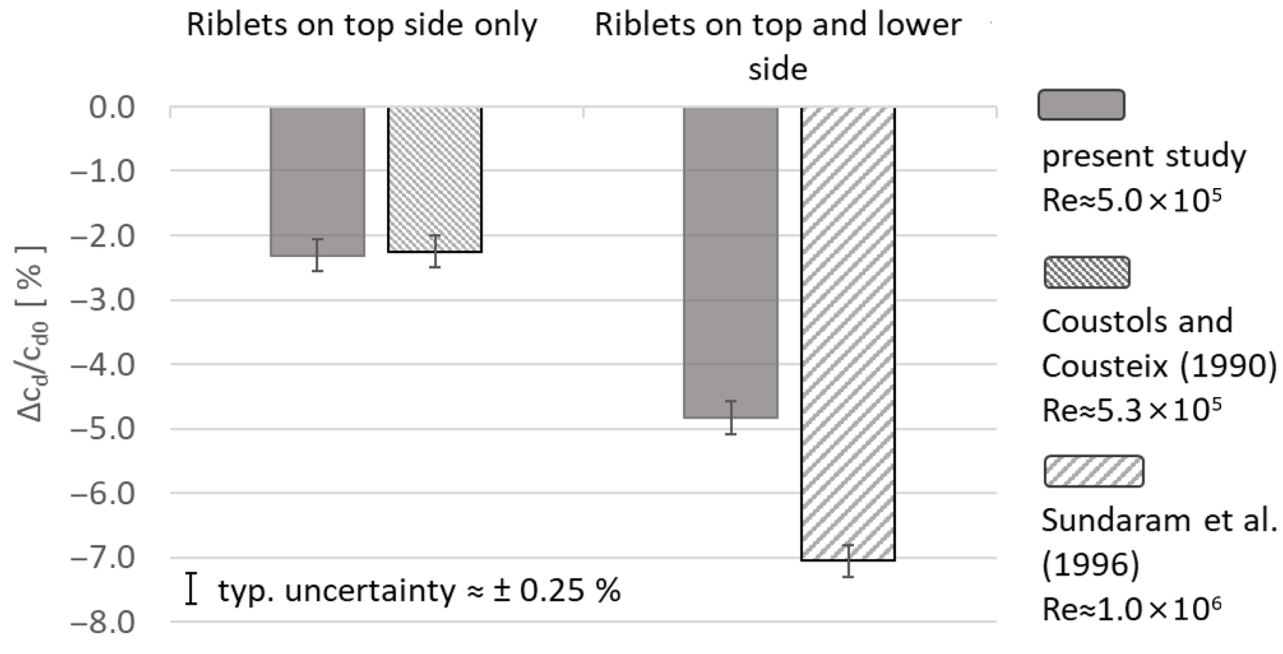
8] were applied to both the suction and pressure sides of the airfoil. In all studies, including the present one, tripping devices were installed upstream of the riblet region to ensure a fully turbulent boundary layer, which is essential for a meaningful comparison of riblet performance under given flow conditions. Moreover, the aerodynamic evaluation in each case was based on wake flow measurements, where the momentum deficit was analyzed to quantify the impact of riblets on overall drag.
Figure 24 presents a comparison of the drag reduction achieved in the present study with the results reported in these previous investigations.
For the one-sided riblet application, the results reported by [
7] show very good agreement with the wake survey data obtained in the present study. A comparable drag reduction of
was measured, confirming the consistency of the measurement approach and supporting the validity of the results. When riblets are applied to both sides of the airfoil, the present experiments reveal an almost doubling of drag-reduction effectiveness. For a symmetric airfoil such as the NACA0012 at zero angle of attack, this additive increase is consistent with the working hypothesis that the aerodynamic effects on the suction and pressure sides are largely independent and cumulative.
However, the results presented by [
8] show a significantly higher drag reduction in the two-sided configuration. This discrepancy is most likely due to differences in Reynolds number and the associated boundary-layer characteristics, as well as the use of tripping devices to enforce transition. At lower Reynolds numbers, the boundary layer is naturally thicker, requiring stronger disturbances to trigger transition. These more pronounced tripping elements increase baseline drag through additional pressure losses, which can distort the apparent relative benefit of riblet structures. The present results therefore highlight a fundamental experimental limitation: at the Reynolds numbers attainable in conventional low-speed facilities, the use of artificial tripping devices is unavoidable. In contrast, ideal testing conditions, i.e., at sufficiently high Reynolds numbers where natural or bypass transition occurs directly at the leading edge, would allow a more intrinsic assessment of riblet-induced drag reduction without the need for such artificial excitation.
From a broader perspective, the comparison with previous studies reinforces two important conclusions. First, it confirms the robustness of the underlying physical mechanism: riblets consistently reduce skin friction by altering near-wall turbulence structures, independent of geometry, airfoil type, or flow conditions. Second, it illustrates the sensitivity of measured drag reductions to boundary-layer state and experimental methodology, highlighting the importance of careful control and documentation of tripping strategies when comparing results across different facilities or Reynolds-number regimes.
The implications of these findings extend beyond the present configuration. In turbomachinery or aircraft applications, where Reynolds numbers are typically orders of magnitude higher and boundary-layer transition occurs naturally, the relative benefit of riblet structures may differ from low-speed laboratory measurements. Future research should therefore focus on bridging this gap by conducting high-Reynolds-number experiments or direct numerical simulations that capture natural transition processes. Moreover, improved diagnostic techniques capable of resolving wall shear stress distributions on curved surfaces would enable a more direct validation of riblet-induced drag reduction mechanisms.
10.3. Continuously Adapted Riblets
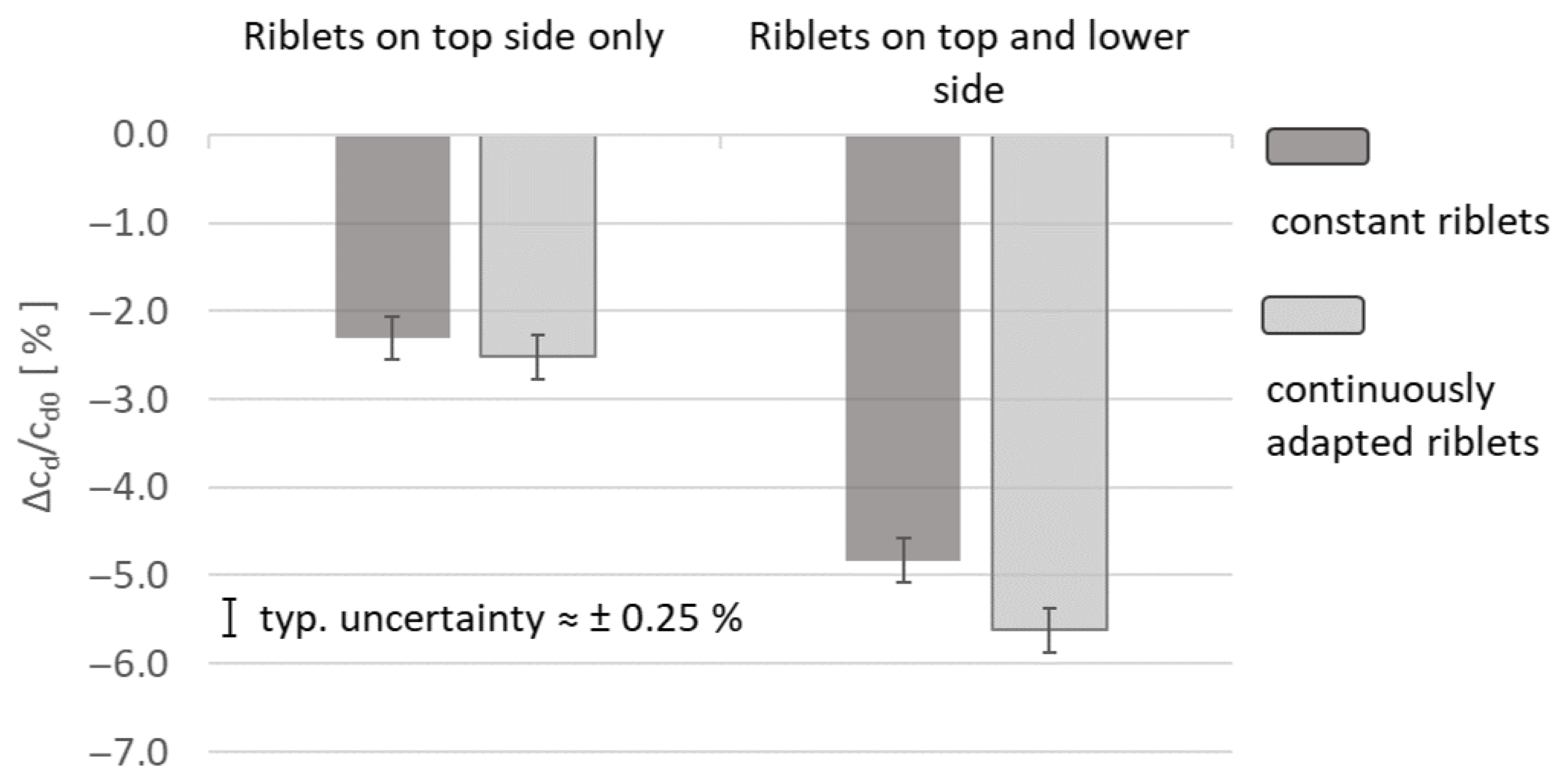
The effectiveness of continuously adapted riblet structures is assessed by comparing the achieved drag reduction with the baseline results for constant riblets presented in the previous section. As before, the one-sided and two-sided applications are analyzed separately to enable a direct assessment of their individual contributions to the overall aerodynamic performance.
Figure 25 summarizes the experimental results and clearly demonstrates that adapting riblet dimensions to local flow conditions can substantially enhance their drag-reducing capability. This improvement is directly linked to the spatial variation in the riblet spacing, which ensures that the non-dimensional groove width
remains close to its optimum value across the entire surface. As a result, skin-friction reduction is maximized locally, and performance losses associated with off-design are minimized. The observed increase in drag reduction, approximately
for the one-sided application and about
for the two-sided case, confirms the fundamental hypothesis that passive surface structures tailored to the local boundary-layer conditions can outperform conventional constant-geometry designs. The approximately additive nature of the improvement for the symmetric NACA0012 profile further supports the assumption that the aerodynamic effects on both sides of the airfoil act largely independently. These findings are consistent with trends reported in earlier studies, which have highlighted the sensitivity of riblet performance to groove spacing and misalignment. However, the present results extend this understanding by experimentally demonstrating that a continuous spatial adaptation of riblet geometry leads to measurable drag-reduction gains under realistic aerodynamic conditions. This has important implications for turbomachinery and external aerodynamic applications, where local flow properties can vary significantly along a surface and where conventional riblets, optimized only for average conditions, exhibit limited effectiveness. In a broader context, the present study underscores the potential of spatially tailored surface structures as a passive flow-control strategy in environments characterized by strong three-dimensionality, pressure gradients, or unsteady boundary layers. Therefore, future research should focus on extending the adaptation principle to more complex application scenarios.
11. Conclusions
The present study investigated the aerodynamic performance of both constant and continuously adapted riblet structures on a NACA0012 airfoil using a combination of experimental wake measurements and numerical analysis. The results demonstrate that passive surface modifications remain a highly effective approach for reducing skin friction and improving aerodynamic efficiency. Compared to conventional riblets with constant dimensions, continuously adapted riblets showed a significant enhancement in drag reduction. By tailoring the riblet spacing and orientation to the local flow conditions, the drag-reduction effect increased by approximately for one-sided application and by up to for two-sided application. These findings confirm the underlying hypothesis that local optimization of surface geometry can substantially increase the effectiveness of passive flow-control strategies.
From an application perspective, the demonstrated gains in drag reduction underline the potential of spatially tailored riblet surfaces in industrial contexts ranging from aerospace components to turbomachinery. Advanced manufacturing technologies, particularly ultrashort-pulsed laser processing, offer the flexibility and precision required to realize such complex surface morphologies on technical scales. However, further work is needed to ensure that designs optimized for a specific operating condition do not compromise performance under varying flow conditions.
Future research should aim to deepen the understanding of riblet–turbulence interactions in complex three-dimensional and transitional flows and extend experimental investigations to significantly higher Reynolds numbers. Direct wall shear stress measurements, systematic parameter variations under varying flow conditions, and studies on durability and fouling resistance are essential to assess long-term performance. On the numerical side, high-fidelity simulations and improved RANS models will be key to predicting riblet effectiveness in practical configurations. Such efforts will be essential to fully exploit the potential of adaptive surface structuring and to translate these promising laboratory results into real-world aerodynamic and turbomachinery applications.