1. Introduction
Retinitis pigmentosa and Glaucoma are degenerative eye diseases leading to a progressive loss of the field of view, and eventually to complete blindness. The evolution of the disease is generally slow, and several decades can be observed between disease onset and blindness [
1]. To date, there is no treatment leading to the recovery of the field of view. In both diseases, peripheral vision is first impaired, causing what is called “tunnel vision” with important consequences on visual search [
2,
3], and hence mobility and autonomy [
4]. Visual searches are performed all day long for many different tasks (e.g., picking up a cell phone, finding a product on a shelf in a supermarket, looking for a friend in a crowded space…). It gets more challenging and time consuming when the visual complexity of the environment increases [
5], especially with visual field impairment [
6].
Many technologies have been designed to enhance space perception and then improve visual search for people with limited field of view. Some are based on the remaining visual capacities, while other ones rely on the auditory and tactile modalities. Specific devices for tunnel vision have been designed to enhance visual awareness, specifically for targets that are outside of the field of view. These devices bring visual information back into the residual field of view. One possibility consists in compressing visual information with optical “minification” [
7,
8]. Another series of devices relies on prisms that deviate light to the remaining field of view or to the other eye [
9]. In devices based on augmented reality, specific visual information (e.g., contours) can also be superposed on the intact field of view [
10]. In all these cases, the remaining field of view is cluttered with much more visual information, which impairs visual acuity, disrupts normal eye movements, and changes spatial relationship between objects [
11]. All these drawbacks may have a negative impact on visual search [
12].
Devices based on the auditory modality have also been designed for visually impaired people. The more generic systems (e.g., the vOICe) aim at converting the whole visual scene into auditory signals, and provide the user with sufficient information for locomotion, localization, or pointing tasks [
13]. However, with such devices, even simple pointing tasks require careful attention, and need a lot of time. In addition, visually impaired people rely on natural sounds for many behavioral tasks, and hence are reluctant to obstruct the auditory system with additional information.
The tactile modality has also been used as a sensory substitution modality from visually impaired person, converting portions of space into tactile signals [
14,
15]. Basic geometrical shapes can be recognized, which enhances spatial perception. However, after more than forty years of sensory substitution research, none of the device proved to be usable in ecological conditions [
16]. In particular, it appears that they are not really usable in order to locate a specific object in cluttered scenes.
Instead of substituting the whole visual scene, auditory and tactile displays can be used to pinpoint the location of a single target or point of interest in that scene [
17]. In the context of tunnel vision, it is possible to guide the gaze or the hand towards a specific region in the surroundings. For instance, it is possible to facilitate pointing and reaching of a single target with binaural sounds rendering the azimuth and elevation of that target only [
18,
19]. However, as mentioned before, additional auditory information interfere with natural sounds from the environment, which reduces their effectiveness, and masks potential dangers [
20]. In this work, we chose to design a tactile display that helps to localize specific targets in space. We first review existing research projects, and then describe the design choices that we made, and the different experiments with simulated and real restricted fields of view.
2. Tactile Displays for Spatial Perception
Tactile stimulations are private and not intrusive, and they do not interfere with processing ecological auditory or visual stimuli [
21]. In addition, the somatosensory system is able to discriminate both spatial and temporal cues [
22]. Tactile displays have been used in a great number of applications including orientation, navigation, notifications, alerts, feedbacks, etc. For instance, Boll and colleagues [
23,
24] used a tactile display on the wrist or chest in order to assist both orientation and navigation. It can also be used for indicating proximal objects in order to prevent collision during mobility [
25]. Previous work also focused on localizing a specific target in the surrounding area. In this domain, two kinds of cues have been described by Lehtinen
et al. [
26]: the guiding cues, and the preview cues. The guiding cues provide continuous information related to the ongoing error between the target and a moving body part, generally the hand. The preview cues indicate a direction or a segment of space to focus on before the scene is actually explored. Guiding cues can drive the attention towards a precise location in space, which is particularly useful when the target is hidden in highly cluttered scenes, and hence does not pop out [
26,
27,
28,
29,
30]. For instance, Lehtinen et al. [
26] placed two vibrators on the palm and two on the back of the hand. In their experiment, the hand was continuously guided towards a B letter among numerous distractive P letters. With tactile guidance, they observed a significant reduction of the time needed to find the B letter. However, subjects reported “first focusing on the tactile signal” and then “jumping to the indicated area with the gaze”. In doing so, the subjects in fact ignored the continuous guiding cues. They rather used the tactile signal as a preview cue, and then executed a visual search in a specific region of space. In addition, they reported being “not convinced that guidance offers value beyond this phase”. Hence it seems that guiding cues are less relevant than preview cues. Preview cues do not increase cognitive load, and let attentional resources unengaged for the upcoming exploration, which is particularly important during a complex visual search. This might be especially true for people with tunnel vision.
Preview cues have been used to indicate a portion of space before a visual search [
31,
32,
33]. Experiments showed significant reduction of searching time. However, they were used to provide imprecise directional information concerning a limited portion (e.g., top-left corner) of virtual spaces that are not representative to everyday life environments. Then the question remains if preview tactile cues could assist visually impaired users, and specifically people with tunnel vision, to find specific targets in their surroundings. In that case, preview cues need to communicate a precise and small segment of space, close enough to the target of interest. Actually, the designated region should be smaller than the remaining field of view of the user. This study investigated tactile preview cues as an efficient modality to provide a user with tunnel vision with the precise location of a specific target in the surrounding area.
3. Study 1: Wrist-Based Tactile Code
3.1. Design of the Tactile Code
In this first experiment, we aimed at designing the tactile code (shape and reference frame) that was the most efficient to locate a cue in the surrounding space. The design of the tactile display in the context of a visual search task has been addressed in the second experiment.
3.1.1. Reference Frame and Coordinate System
In a device assisting visual search for people with low vision, cameras are almost mandatory. They are easily mountable on goggles and can be used to locate the expected target in the visual scene. The system may also integrate an accelerometer and a gyroscope for compensating the low temporal frequency of the camera [
34]. The most logical reference frame for guiding the gaze towards the localized target would be that of the eyes, with the fovea being its center. Then, assuming that the target has been localized by the camera attached to the head, the tactile cue can directly indicate the error between the fovea and the target. However, a wearable eye tracker monitoring gaze position would then be mandatory too. Wearable eye trackers are expensive and must frequently be calibrated. As eyes and head are synchronized during gaze movements [
35], head is also an adapted reference frame for assisting visual search. Using the head as the reference frame is simpler and cheaper, because it relies on the embedded camera only. The tactile cues can directly indicate the error between the actual head orientation and the target localized in the image, without any coordinate transformation.
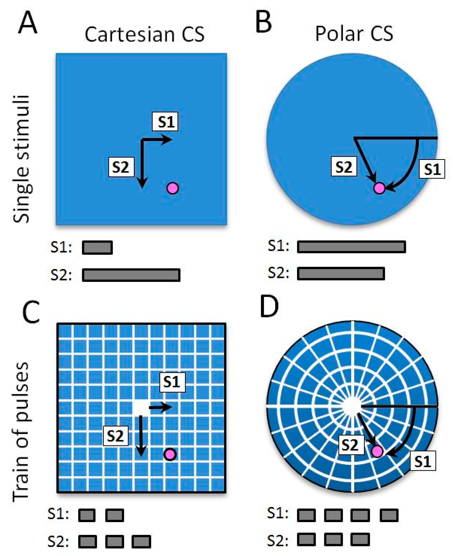
Visual target localization in space relies on three coordinates in a reference frame, namely azimuth, elevation and depth. However, depth between the user and the target is not essential for visual search. Indeed, when the target is located within the image plane of the camera, it is enough to bring the field of view in front of the target, which requires providing two coordinates only (azimuth and elevation). In order to render these two target coordinates with a vibrator, we evaluated two different coordinate systems (CS): a Cartesian CS and a Polar CS.
In the Cartesian CS, target location was decomposed into two successive tactile cues according to the actual head orientation. The azimuth coordinate (horizontal axis) was presented first, and the elevation (vertical axis) was presented afterwards. In the polar system, azimuth and elevation of the target location were converted into two successive stimulations rendering one clockwise angle (rendered in relation to a polar axis) and one radial distance.
3.1.2. Tactile Code
As previously mentioned, preview cues do not continuously communicate the error between the actual position and the expected target. After a brief stimulation, the user must be able to estimate the target location with good accuracy. If the first cue is not explicit enough, the user will have to ask another preview cue to find the target, which is not appropriate. Hence the tactile cue must be spatially informative and as short as possible in order to assist the upcoming visual search. We evaluated two different tactile codes (
Figure 1). The first one was based on a single tactile vibration, which duration was proportional to the error angle between the head and the target. The maximal duration was 1.5 s corresponding to a maximum angle of 45°. This duration was set based on pretests (not detailed here) which showed good tradeoff between time discrimination and stimulus duration. In the second tactile code, a coordinate was defined as a train of short pulses with a fixed duration (200 ms separated by a 100 ms gap). The number of pulses in the train corresponded to an expected zone in space. Each train corresponded to a zone of nine degrees of visual angle. The maximum number of stimuli was five, corresponding to the maximum angle of 45°.
These two different codes were evaluated in the two CS described previously. Hence four different techniques were evaluated: a single stimulus in a Cartesian CS, train of pulses in a Cartesian CS, a single stimulus in a Polar CS, and train of pulses in a Polar CS (see
Figure 1).
3.1.3. Tactile Display Positioning
Tactile displays have been placed on different parts of the human body. In order to assist visual search, one could think about a tactile display around the eye. It could be efficient because the spatial mapping between the stimulation and the required eye movement would be intuitive. However, tactile sensitivity on the face is very important. The tactile display may rapidly provoke skin irritation. In addition, all the subjects that we questioned were reluctant to wear a tactile display on the face.
In previous studies, directional cues were mostly displayed via devices attached on the belt, back and hands. Belt is an elegant and nonintrusive solution to display azimuthal [
23,
36], but not elevation cues. The back and torso present important tactile surfaces where multiple vibrators can be placed. Previous studies used vibrators placed on a chair in order to display preview cues on the back before visual search [
31,
33]. This device was not mobile and hence limited in-situ interaction. Vibrators may also be placed within a specific suit that is functional but may decrease acceptability of the assistive device [
37]. The hand has often been used to display guiding cues [
26,
27,
28,
29]. This is obviously an advantage when hand movement is required. Indeed it avoids transforming the reference frame between the display and the effector, and then facilitates the pointing task. However, displays that are placed in the palm of the hand prevent natural grasping and manipulation. Back of the hand or wrist are good alternatives. Wrist can provide efficient discrimination and detection performances [
38,
39,
40]. Compared to back or hip, wrist is involved in the visuomotor process allowing eye-hand coordination [
41]. Another strong argument for attaching the display onto the wrist is the important spread of smartwatches, including in the community of people with visual impairment. In addition, smartwatches already include one vibrator that could be addressed with a Bluetooth connection. If needed, additional vibrators could be attached to the bracelet of the smartwatch.
3.2. Design of the Evaluation
We evaluated the usability of the four techniques with a head pointing task. Sighted subjects wore a virtual helmet that provided a restricted field of view of ten degrees of visual angle only. For each condition, they had to estimate as precisely as possible a target location after receiving a preview tactile cue. We used a two by two factorial design with CS (Cartesian vs. Polar) and tactile code (Single vs. Train) as the main factors.
3.2.1. Participants
Six sighted subjects (four males and two females, 27.2 ± 2.6 years old) performed the experiment, on which tunnel vision was simulated with a VR helmet. They provided written informed consent before participating in the study, in accordance with the Helsinki Declaration. The study was also approved by a local ethics committee (CLERIT, Toulouse, France).
3.2.2. Experimental Setup and Stimuli
Subjects were placed in an artificial visual scene containing noisy background only (which looked like a stellar galaxy). The background was useful to provide optic flow stimulation during head movement but did not provide any information (semantic or symbolic) that could serve as a landmark. During the experiment, the subject’s field of view was restricted to ten degrees in the virtual helmet by using a black mask covering everything at the periphery.
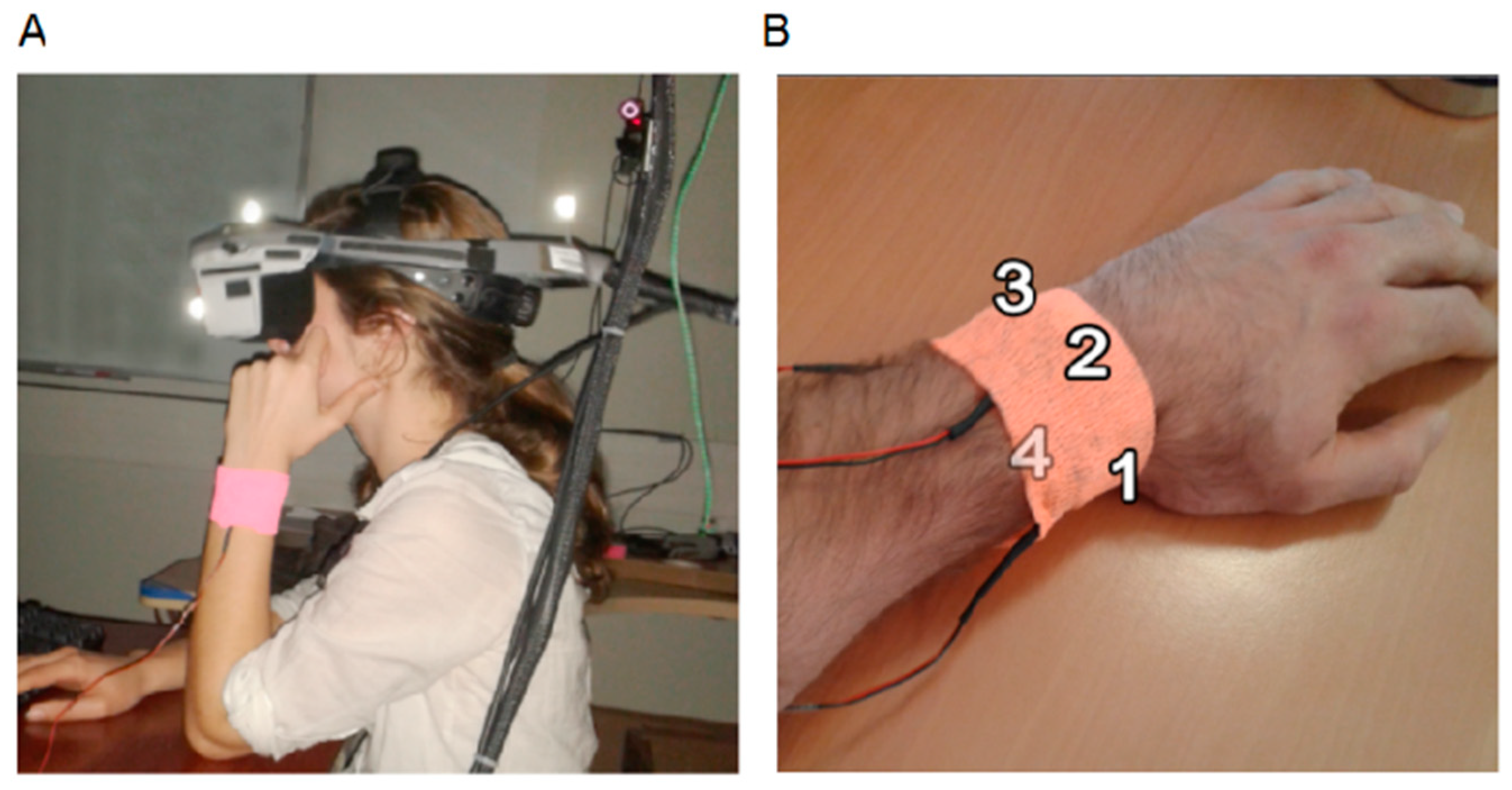
Visual stimuli were presented with a virtual helmet, the nVisor™ SX-60 HMD (NVIS Inc., Westborough, MA, USA), having a resolution of 1280 × 1024 pixels, and subtending 44 × 34 degrees of visual angle (
Figure 2A). The orientation of the virtual camera was attached to the orientation of the head with a motion capture system running at 60 Hz (OptiTrack™, Natural Point, Beaverton, OR, USA). As a result, subjects could look around in the virtual environments when moving the head. Subjects were seated in a static chair, their back lying on the chair, and hence minimizing trunk movement. Subjects were free to move the eyes, but a red cross was shown in the center of the field of view, serving as an anchoring point.
The virtual environment was generated and animated using the open source Irrlicht 3D engine (v1.8). The tactile display was specifically developed for the experiment using an Arduino™ ATmega1280 and tactile vibrators VPM2. It was fastened with a cohesive bandage on the posterior part of the wrist. Tactile stimuli were displayed on one vibrator placed at the top of the wrist. Vibration frequency was set to 250 Hz, which is an optimal frequency for tactile stimulation on the skin [
42].
3.2.3. Experimental Protocol
Subjects were tested in a head pointing task in presence of the experimenter. In that experiment, they had to estimate as precisely as possible the location of a random target in the virtual environment.
At the beginning of the experiment, each subject was required to define a “resting position” with the head pointing straight-ahead. At the beginning of each trial, the resting position was marked with a green sphere (2° diameter), and the subject was asked to place the center of his visual field (indicated with the grey cross) directly onto that green sphere. Then, the target position was randomly selected within a portion of 90° × 90° of visual angle. After a random delay of 1.4 to 2 s, the coordinates of the target were rendered through the tactile display. After the green sphere disappeared, the subject had to orient the head as precisely as possible towards the invisible target, and to press the space bar on a keyboard to validate the pointing direction. The target location and the pointing direction were then indicated with a red and white sphere, respectively, which provided the subject with a visual feedback of the pointing error for each trial. Another trial started when he returned to the resting position.
Each subject performed four blocks corresponding to the four conditions (Cartesian vs. Polar; Single vs. Train) in a pseudo-random order, which was different across participants to overcome possible learning effects. In each block, the first twenty trials were used as a familiarization phase and were not included in the results. They were followed by forty trials where the head pointing accuracy was recorded.
In that first experiment, we aimed to evaluate the tactile code relying on a single vibrator only. For each trial, one of the four quadrants was randomly selected and indicated with a visual cue: in the Cartesian CS condition, a red arrow was successively displayed on two semi axes; in the Polar CS condition, a red bar indicated one semi axis among the four possible ones (noon, three, six or nine hours on a clock face). Then, the subject received two tactile stimulations corresponding to the target coordinates in the Cartesian (x, y) and Polar (t, r) CS conditions. A short gap of 0.5 s separated the two stimulations. This design was chosen in order to constrain the stimulation onto one vibrator, independently of the quadrant of space being addressed, and thus allowing the subjects to focus on the decoding of unsigned coordinates only.
At the end of each block, subjects completed a usability questionnaire (System Usability Scale) about the technique that has been used. Overall, the experiment lasted about 1.5 hours per subject.
3.3. Results
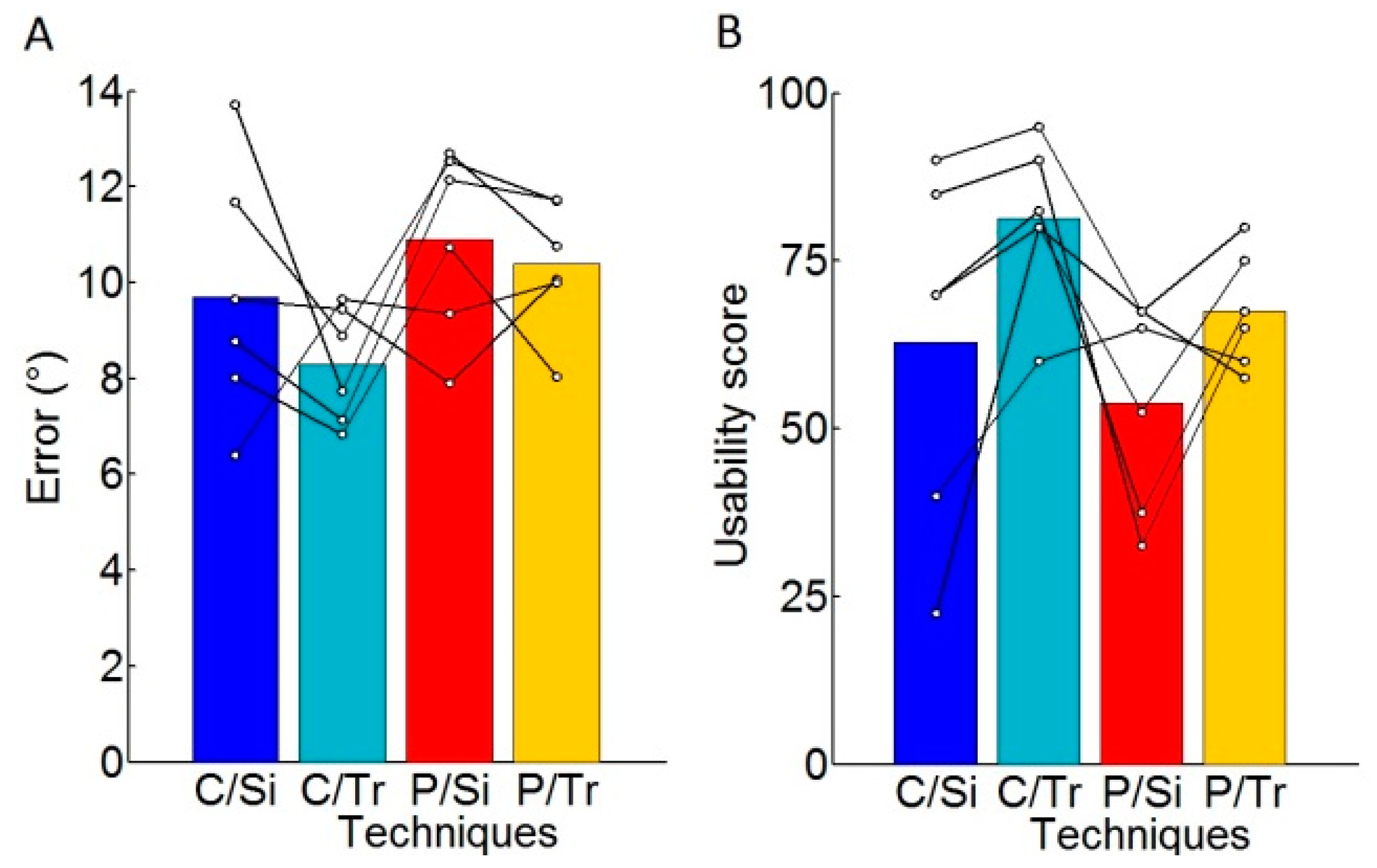
The pointing error was computed for each trial and averaged per subject and per technique. The pointing error corresponds to the error between the final head pointing position and the expected target location (
Figure 3). The results show that Cartesian CS significantly reduced the pointing response error compared to Polar CS (9.0° ± 2.1° vs. 10.6° ± 1.6°,
t-test
p < 0.05).
In order to reveal the existence of a systematic cognitive or motor bias, like under- or overestimation of the two coordinates, we computed the mean pointing errors within each reference frame. In average, subjects did not show any bias within the Cartesian CS. However, within the Polar CS, they significantly underestimated the target location indicated with the “single stimuli” (t-test, p < 0.05 after Bonferroni correction). Within that same Polar CS, target position was significantly overestimated when indicated with the “Train of pulses” (t-test, p < 0.05 after Bonferroni correction). In addition, the pointing error is more important for distal target than for proximal target with an average factor of 1.7.
A usability score was obtained for each technique with a SUS questionnaire. “Train of pulses” were considered as more usable than “single stimuli” (t-test, p < 0.05). During the final interviews, four subjects considered the Cartesian CS with train of pulses as their favorite technique among the four that were designed. The two other subjects considered this technique as a second choice.
3.4. Conclusions about the First Experiment
Head pointing responses were more accurate within the Cartesian CS than the Polar CS. In addition, in the Cartesian CS, we did not observe any cognitive bias, and the error was in average of 9.0 degrees of visual angle. On the contrary, the tactile cues within the polar CS led to significantly less accurate results, with systematic biases. Hence, it appears that the Cartesian CS is a more precise system for communicating the target location with the tactile display.
The usability of these two systems was not significantly different. However, it was better when the coordinates were communicated with a train of pulses than with a single stimulus. When combining accuracy and usability, it appears that the Cartesian CS with a train of pulses is the best technique among the four that we designed. This technique showed the lowest inter subject variability and the best average SUS score, reaching 81 ± 12, which is considered to be a “good” device [
43]. Hence, the first experiment allowed choosing C/Tr as the best technique to provide the coordinates of a surrounding target.
4. Study 2: Visual Search of a Small Target within a Virtual Living Room
In this follow-up experiment, we aimed at evaluating the most efficient and preferred technique (C/Tr) in conditions that are similar to ecological situation. Here again, tunnel vision (field of view of ten degrees of visual angle) was simulated on sighted subjects wearing a VR helmet. They were immerged in a living room and had to locate as quickly as possible a target within this room.
4.1. Participants
Ten subjects (six males and four females, 25.4 ± 1.6 years old) performed the experiment. They provided written informed consent before participating in the study in accordance with the Helsinki Declaration. The study was also approved by the local ethics committee (name and reference hidden for blind review).
4.2. Virtual Environment, Tactile Display and Stimuli
The experimental setup used in this experiment was identical to the one used in the previous experiment.
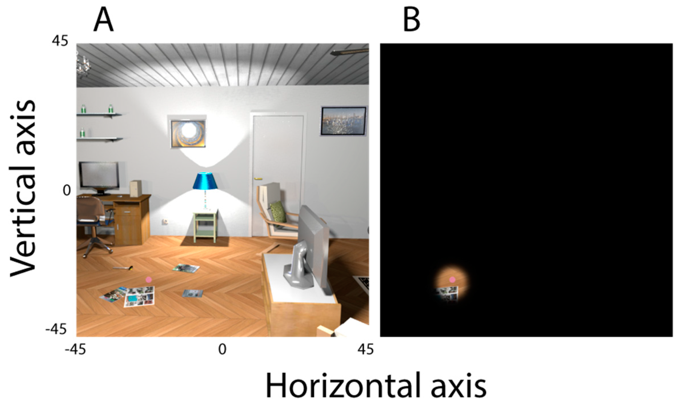
A virtual scene depicting a living room was created on “Sweet Home 3D
®” (
Figure 4). A high number of salient objects (lamp, chair, book, etc.) were placed homogenously in the entire visual scene. The target, a pink sphere (1° radius) was randomly placed in the virtual scene, within a portion of 90° × 90° of visual angle centered on the head position before each trial. Particular attention has been paid to avoiding confusion between targets and the rest of the visual scene. Consequently, pink hues were not used in the rest of the visual scene. However, in order to avoid a strong pop out effect of the target, it was slightly transparent. During the whole experiment, the subject’s field of view within the virtual helmet was limited to 10° by applying a black mask on the periphery, which simulated a severe tunnel vision.
As a result of the first experiment, the two coordinates of the target were rendered with two successive trains of tactile stimuli encoded within a Cartesian coordinate system. However, in this experiment, the tactile cues were displayed on four vibrators placed around the left wrist (on the anterior and posterior parts, and on the thumb and pinky sides,
Figure 2B). The vibrators were fastened with a cohesive bandage. The mapping of the axes and their sign was arbitrarily chosen according to a common resting position of the hand. Horizontal coordinates were rendered via the vibrators placed on the thumb and the pinky sides, with the thumb side for targets on the right side. Vertical coordinates were rendered via the posterior and anterior vibrators, with the posterior side for targets on the top. As in the first experiment, the tactile pulses had a fixed duration of 200 ms separated by a 100 ms gap. The number of pulses in the train corresponded to the expected zone in space, with one pulse indicating a zone of 9°. The maximum number of stimuli was five, corresponding to a maximum of 45°.
4.3. Experimental Design and Procedure
Subjects were tested individually during a visual search task in presence of the experimenter. They were asked to locate as quickly as possible a target represented as a pink sphere in the virtual scene. As in the previous task, the resting head position was defined at the beginning of the experiment and was marked in the virtual environment by a green sphere (2° diameter) when needed. The subjects were required to reach that position before any trial. When the position was acquired, the artificial lights in the living room were switched off. After a random time between 0.7 and 1.4 s, the coordinates of the target were rendered on the tactile display. At the end of the stimulation the green sphere disappeared, and the lights were switched on indicating to the subjects that they must start searching. They were asked to find the target as quickly as possible and had to validate the position by pressing the spacebar. Each subject completed a training of fifteen trials in order to get familiar with the tactile rendering. Then, he completed forty trials divided in two blocks during which visual search duration and head movements were recorded.
In this experiment, the assistive technique using the Cartesian coordinate and the train of pulses was compared to a control condition without any tactile cue regarding the target location. Except the absence of tactile cues, the task was identical. Fifty-percent of the subjects performed the control condition first; and then the condition with tactile assistance. The other fifty percent did the opposite. The whole experiment lasted about sixty minutes. At the end of the experiment, the subjects were asked to complete a usability questionnaire (System Usability Scale) about the assistive device.
4.4. Data Analysis
We measured the duration elapsed between the initiation of the first stimulation and the spacebar being pressed. It corresponds to the time needed for both the visual search and the head pointing response. As the pointing response is a simple task when target is in the visual field, the duration mostly reflects visual search. Head movements were monitored during the whole period with a motion capture device (60 Hz), which allowed examining head movements during the visual search for each trial. A bivariate kernel density estimator was used to extract density map of searching pattern. The total travelled distance was computed and normalized for each trial according to the shortest distance between the resting position and the target. This normalized distance is complementary to the duration with the aim of describing the subject’s behavior during visual search.
4.5. Results
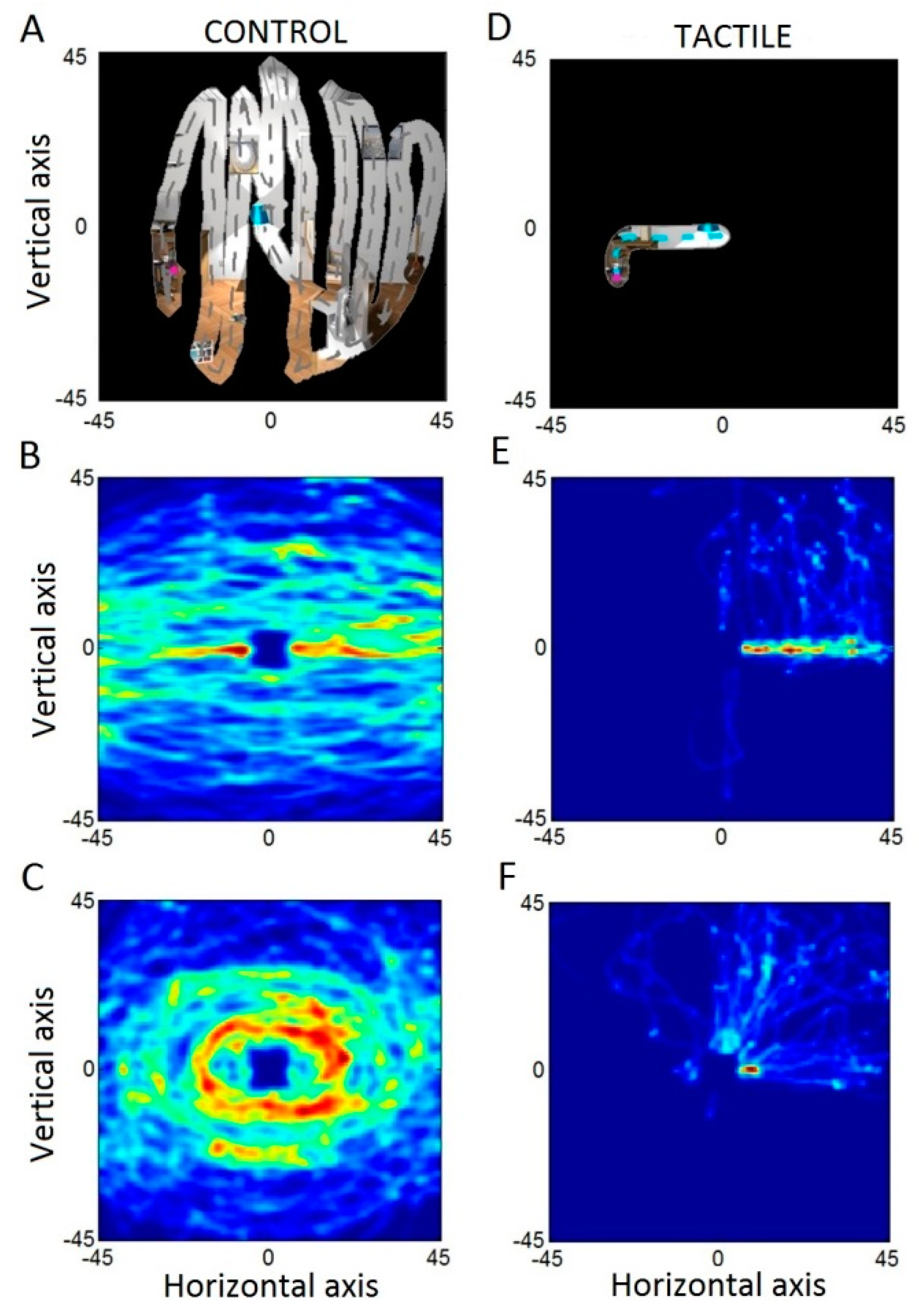
In the control condition, we observed different visual search strategies depending on the subject (
Figure 5). Four subjects performed a clear scanning pattern either on vertical or horizontal axis (
Figure 5A,B). One subject performed concentric circles around the center of the reference frame (
Figure 5C). These patterns were not observed in the presence of tactile cues. In this condition, the subjects moved the head on the horizontal axis first, and then on the vertical one, following the two coordinates rendered by the tactile display (
Figure 5D,E). We also observed, for some subjects, diagonal movements suggesting an integration of the two coordinates (horizontal and vertical) before the head movement (
Figure 5F).
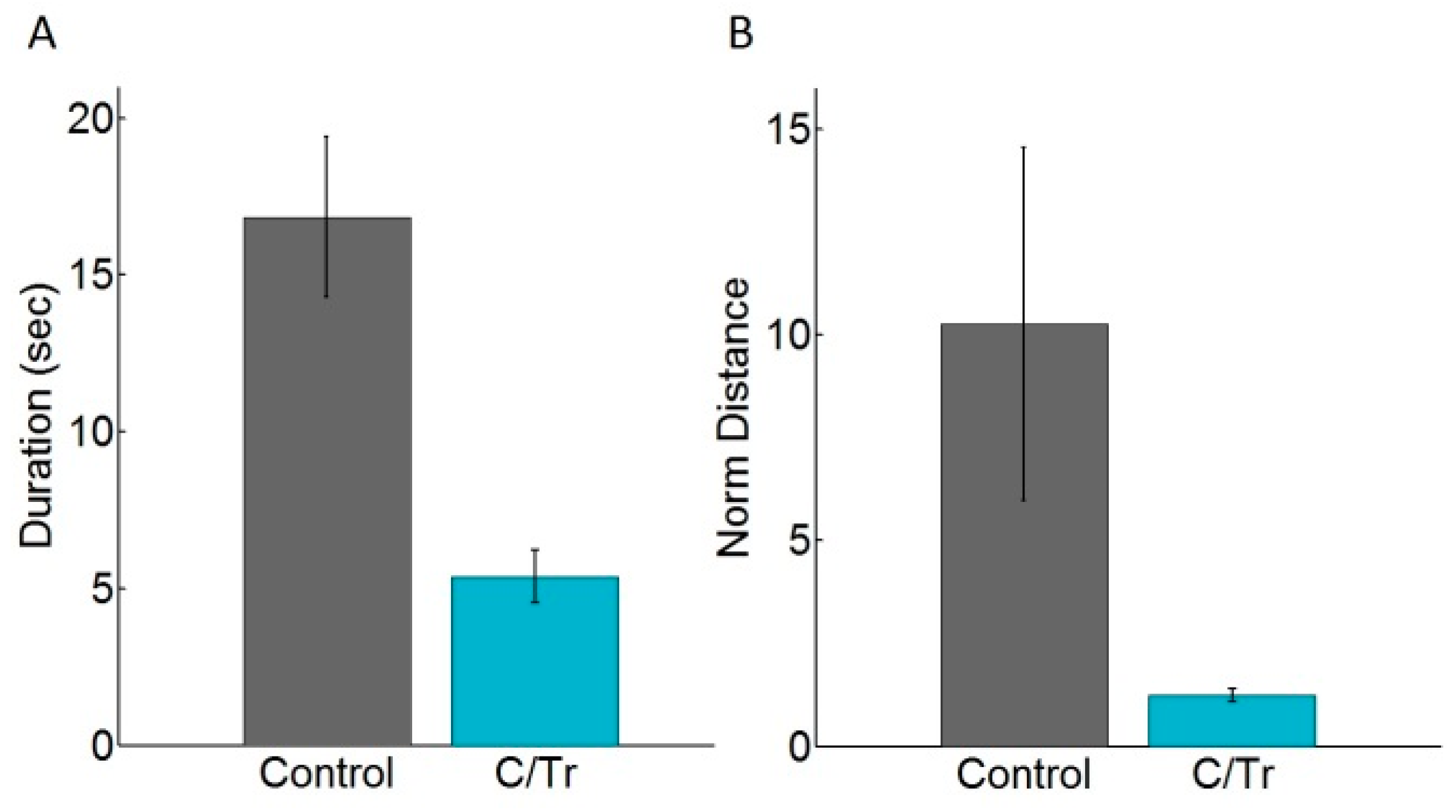
We computed the median duration to find the target per subject and per condition (with and without tactile cues). The averages of these median durations are presented in
Figure 6A. Subjects spent in average 16.8 ± 2.5 s to find a target in the control condition. The duration dropped down to 5.4 ± 0.8 s with tactile cues. We observed a similar difference for each subject. Accordingly, the difference was highly significant (
t-test,
p < 0.001). We also computed the median distance travelled by the head per subject and per condition. In the control condition, they were in average ten times larger than the minimum distance between the target and the resting position (
Figure 6B). With tactile cues, this ratio was on average 1.2 ± 0.2. We observed a similar ratio for each subject. Hence, the difference was also highly significant (
t-test
p < 0.001). No improvements of time or distance travelled across trials were observed either in control or tactile conditions.
A typical error was observed with tactile assistance: the inversion up/down, left/right. We computed inversion errors according to a simple rule: an error was detected when the head moved towards the opposite direction and reached the threshold of five degrees of visual angle. In average, the subjects made 4.5 ± 3.3% and 8.8 ± 4.0% of inversion errors on the horizontal and vertical axis respectively. The usability score (SUS) for the assistive technique was on average 82 ± 16.23, which is considered “good” [
43].
4.6. Conclusions about the Second Experiment
The experiment showed that visual search with tactile assistance was in average three times shorter. In addition, tactile assistance was reliable and satisfactory. Hence, this experiment clearly demonstrated the usability of the technique for assisting visual searches in a cluttered environment.
6. Discussion
In the first experiment, we designed four different tactile codes rendered on a single vibrator attached to the wrist. These preview cues were rendered before any head movement and aimed to provide assistance with locating a target in the frontal space. The first observation was that all these different types of preview cues provide the user with an estimate of the location of a target related to the actual orientation of the head. They can all communicate an accurate knowledge about target location within an ego-centered reference frame, which is similar to how spatial memory can store spatial location [
45].
However, the direct comparison of the four techniques during a head pointing task with artificial tunnel vision showed that a succession of two trains of pulses rendered in a Cartesian coordinate system were more efficient and more satisfactory. In this technique, the two trains of pulses correspond to the abscissa and ordinate of the target related to the actual orientation of the head. Conceptually, an increasing number of tactile cues within the train indicates a portion of space that is further away from the actual head orientation.
In the follow-up experiment, we evaluated the most efficient and satisfactory technique in a more ecological situation. In this experiment, the users were, as in the first experiment, sighted subjects with an artificial tunnel vision. They saw a small portion of the visual field only (10° of visual angle). They had to find a small target within a cluttered living room. In this experiment, we designed a tactile display based on four different vibrators distributed around the wrist. We chose to map the four main directions onto these four different vibrators. The evaluation showed that two trains of tactile cues provided an efficient estimate of the location of the target within the environment. Once again, it is important to note that it was not a guidance signal but a preview cue that allows estimating the target position according to the actual head orientation. The visual search in a cluttered environment was three time shorter with preview cues. The distance needed to find the target was ten times shorter, and all the subjects showed a significant reduction of searching time and distance. Another important observation is that the directions were in the vast majority of cases (more than 90%) correctly interpreted, which suggests almost no confusion in tactor discrimination around the wrist, neither in mental decoding.
As we mentioned, duration of tactile stimulation was set based on brief pretest defining a good tradeoff between time discrimination and stimulus duration. Physiologically, temporal discrimination between two stimulations is in average between 25 ms and 40 ms, depending on the body part stimulated [
22]. It would be possible to reduce both time stimulation and delayed between train stimulation but feelings about stimulation varied across subjects. Healthy subjects (experiment 1 and 2) did not mention possible optimization about timing stimulation, whereas subject with tunnel vision wished to slow down frequency of train pulses. Numerous factors may impact the perception of the tactile stimulation (sensory loss, fatigue, age, etc.). A systematic study could optimize both duration and frequency of train pulses or these parameters could be defined by the subject himself.
During the course of the experiment, we did not observe any decrease of time or travelled distance across trials. It means that the user needed less than the fifteen trials that we used during the familiarization phase to reach a plateau of performance, which suggests an easy and quick learning of the tactile code. Finally, although it was a very low-cost prototype (vibrators attached with a bandaging tape), this device received a high score of usability (82), which is a prerequisite for the acceptance of a potential assistive device.
An important improvement of the technique will be to increase the range, i.e. indicating target location in a larger zone, even 360° around the user. To do so, decreasing duration of train pulses and latency between them will allowed additional pulses coding for a larger area. Other approach based on multimodality or improving single stimulus may be investigated.
Altogether, these results show that the technique that we designed is cheap, accurate, quick to learn, and well accepted. Hence it could be an efficient technique to communicate a priori knowledge about targets of interest within the surroundings for people with a restricted field of view.
However, it was important to validate that the model of visual impairment that we used, i.e., a restricted field of view within a VR helmet, was truthful. Different behavioral studies already showed that the model is reliable in spatial cognitive tasks [
46,
47] and spatial memory tasks [
47,
48]. Nevertheless, the model does not supplant an evaluation of the device with people with tunnel vision. They can present other visual impairments such as low contrast detection, color blindness or visual acuity loss that are not simulated in the model [
49,
50]. They can also develop strategies for visual search during the progressive loss of their field of view. These strategies may hinder the results that we observed in this experiment. Hence, we used one subject with a restricted field of view due to glaucoma as a case study. The size of his field of view was similar to our model (10° of visual angle), but in addition, color detection was altered. The evaluation showed that he was three times faster to find a target with tactile assistance than without. This ratio is similar to the ratio observed with the model, although the visually impaired was slightly longer to find the target in both conditions. Lower contrast and color detection may explain this difference.
During debriefing, the subject mentioned that he had to pay attention for distinguishing which vibrator was activated. He also noticed that the train of pulses was sometimes too fast to be correctly interpreted. Nevertheless, he showed a great interest for the technique, and he said that it should be very helpful during everyday life. The SUS score that he gave (72.5) confirmed the good usability of the device.
Transparency suppression may increase pop out effect on the target and facilitate its detection. However, it is important to emphasis that in the experiment 3, pop out effect was identical in the two conditions (with or without tactile displays). Additional analysis showed that percent of improvement to find target were similar between experiment 2 and 3 (67% and 65%, respectively, for experiment 2 and 3), validating the hypothesis that visual search time is indeed reduced by tactile displays.
The last step will be to evaluate the usability of the device in real conditions. The device may be integrated with smart glasses that are currently developed (e.g., Google glass™) or even on sale (see e.g., OrCam
®). All these devices can recognize and locate targets of interest, and then compute their location relative to head orientation. Algorithms in computer vision are in constant progress, and already perform faces and objects recognition with accuracy. It is especially possible to distinguish thousands of objects on the base of real time images [
51]. Targets of interest could be either detected on demand (vocal command), or suggested by the device itself (e.g., potential obstacles or common targets), increasing the awareness of the environment. Finally, a commercial version of the homemade tactile display that we attached on the wrist could easily be integrated into a smartwatch bracelet and addressed with a Bluetooth connection. A recent survey highlighted the increasing interest that visually impaired people show for smartphones and wearable devices [
52]. It is also interesting to note that in addition to visual search, a tactile display on the wrist may be useful in many other everyday situations such as pedestrian navigation [
53] or transportation [
54].


