Article

Experimental Validation of PI Controller Optimization Using LPO and PSO for a DC–DC Boost Converter


by
Luis Daniel Marin Uc
1,
Victor Manuel Ramirez Rivera
1,*,
David Abraham Uribe Sosa
1 and
Belem Saldivar
2
1
Unidad de Energía Renovable, Centro de Investigación Científica de Yucatán (CICY), Secretaría de Ciencia, Humanidades, Tecnología e Innovación (SECIHTI), Carretera Sierra Papacal-Chuburna Puerto, km 5, Sierra Papacal, Mérida 97303, Mexico
2
Centro de Investigación y de Estudios Avanzados del Instituto Politécnico Nacional, Departamento de Control Automático, Av. Instituto Politécnico Nacional 2508, San Pedro Zacatenco, Gustavo A. Madero, Ciudad de México 07360, Mexico
*
Author to whom correspondence should be addressed.
Sci 2026, 8(9), 250; https://doi.org/10.3390/sci8090250
Submission received: 17 July 2026 / Revised: 4 September 2026 / Accepted: 7 September 2026 / Published: 9 September 2026
(This article belongs to the Section Engineering)

Abstract

This work presents the experimental validation of proportional–integral (PI) controller gains for a DC–DC boost converter obtained using two metaheuristic optimization algorithms: Particle Swarm Optimization (PSO) and Lungs Performance Optimization (LPO). The controller gains were previously determined through a simulation-based optimization procedure in which the proportional and integral gains were selected by minimizing a performance-based objective function incorporating settling time and overshoot. In the present study, the optimized gains are implemented in a physical boost converter prototype and experimentally evaluated under varying operating conditions. Their performance is compared with that of a conventional PI controller tuned using the Root Locus method. The experimental results demonstrate stable output-voltage regulation for all evaluated controllers. Under the investigated conditions, the controllers tuned using the metaheuristic approaches exhibit dynamic responses comparable to those obtained with the conventional tuning method. These results provide experimental evidence supporting the applicability of metaheuristic optimization for PI controller tuning in power electronic converters.

1. Introduction

Microgrids have emerged as a promising technological solution for the integration and management of distributed energy resources in modern electrical power systems. These systems integrate renewable energy sources, energy storage devices, power electronic converters, and control systems to enable efficient and reliable energy management. A fundamental objective of a microgrid is to regulate power flow and maintain the stability of key electrical variables, such as voltage and current, despite the intermittency of renewable energy sources and variations in load demand [1]. From a control perspective, microgrids are commonly organized according to a hierarchical control structure consisting of three operational levels [2]. The primary control level provides fast and local regulation of power electronic converters and is responsible for maintaining the desired electrical variables. The secondary control level compensates for steady-state deviations that may arise during operation, while the tertiary control level addresses higher-level energy management and economic optimization. At the primary control level, the Proportional–Integral ( PI ) controller remains one of the most widely adopted control strategies due to its simple structure, low computational requirements, and ease of implementation. In direct current to direct current (DC-DC) power converters, such as buck and boost converters, PI controllers are commonly used to regulate the output voltage by modifying the converter duty cycle through pulse-width modulation (PWM). Several studies have reported the successful application of PI controllers in renewable energy systems and cascade control structures, with controller parameters obtained through analytical and conventional tuning techniques [3,4,5,6]. The performance of a PI controller is strongly influenced by the appropriate selection of its proportional and integral gains. Classical tuning techniques, including the Ziegler–Nichols method, Bode diagram analysis, and Root Locus methods, have traditionally been employed to determine these parameters [7]. However, their effectiveness may be limited when applied to nonlinear and highly dynamic systems, particularly power electronic converters operating under variations in load demand, input voltage, and other operating conditions. These limitations have motivated the development and application of intelligent and metaheuristic optimization techniques for controller parameter tuning [8,9,10,11,12]. Among the available metaheuristic approaches, Particle Swarm Optimization (PSO) has been extensively investigated for determining optimal control parameters in different power converter topologies, including boost, buck, and Ćuk converters, as well as in maximum power point tracking (MPPT) applications [13]. These optimization-based approaches formulate controller tuning as an optimization problem in which a predefined performance index is minimized to obtain control parameters that provide a desirable dynamic response [14,15,16,17,18,19]. More recently, the Lungs Performance Optimization (LPO) algorithm has been proposed as a bio-inspired metaheuristic optimization technique designed to efficiently explore multidimensional search spaces [20]. Its application to engineering optimization problems has motivated its evaluation in control systems and power electronics. Furthermore, according to the No Free Lunch (NFL) Theorem [21], no optimization algorithm can be expected to outperform all other algorithms for every optimization problem. Consequently, the evaluation of alternative optimization techniques under specific engineering conditions remains relevant for identifying suitable approaches for particular control applications [22]. In a previous study, a comparative analysis of the LPO and PSO metaheuristic optimization algorithms was conducted for tuning the gains of a PI controller applied to a DC–DC boost converter. In that study, the procedure employed to determine the controller parameters was presented in detail, and the proposed optimization methodology was developed. The results showed that both methods converged to the same optimal gain values under the evaluated operating conditions. However, when considering the number of iterations required to reach these values, the LPO algorithm exhibited faster convergence, achieving the optimal solution with fewer iterations than PSO. Nevertheless, the analysis was primarily based on numerical simulations, and the optimized gains were therefore not experimentally validated through the implementation of a physical converter prototype [23]. In the present work, the gains obtained using the metaheuristic optimization methods are experimentally implemented, and their performance is evaluated using a physical converter prototype. Thus, this study provides experimental validation of the results previously obtained through numerical simulations. Therefore, this work extends the previous simulation-based study by experimentally validating the PI controller gains obtained using the LPO and PSO algorithms in a physical DC–DC boost converter prototype. The optimized controllers are evaluated under dynamic operating conditions involving variations in the input voltage and load disturbances. In addition, their performance is compared with that of a PI controller tuned using the conventional Root Locus method. This comparison provides an experimental assessment of the dynamic response and voltage regulation achieved by the different tuning approaches and allows the applicability of metaheuristic-based PI tuning to be evaluated under practical operating conditions. The boost converter considered in this study was developed as part of a microgrid platform designed for integration with a 40 V battery bank. The remainder of this paper is organized as follows. Section 2 describes the development of the plant used for the experimental evaluation of the controller gains, consisting of a boost-type power converter. Section 3 presents the methodology employed to determine the PI controller gains using the metaheuristic optimization methods. Section 4 presents the simulation results obtained using the analytical, PSO-based, LPO-based, and conventional tuning approaches. Section 5 presents the experimental validation of the obtained results using the developed converter prototype. Finally, the main conclusions of the study are presented.

2. Design of the Experimental DC–DC Boost Converter

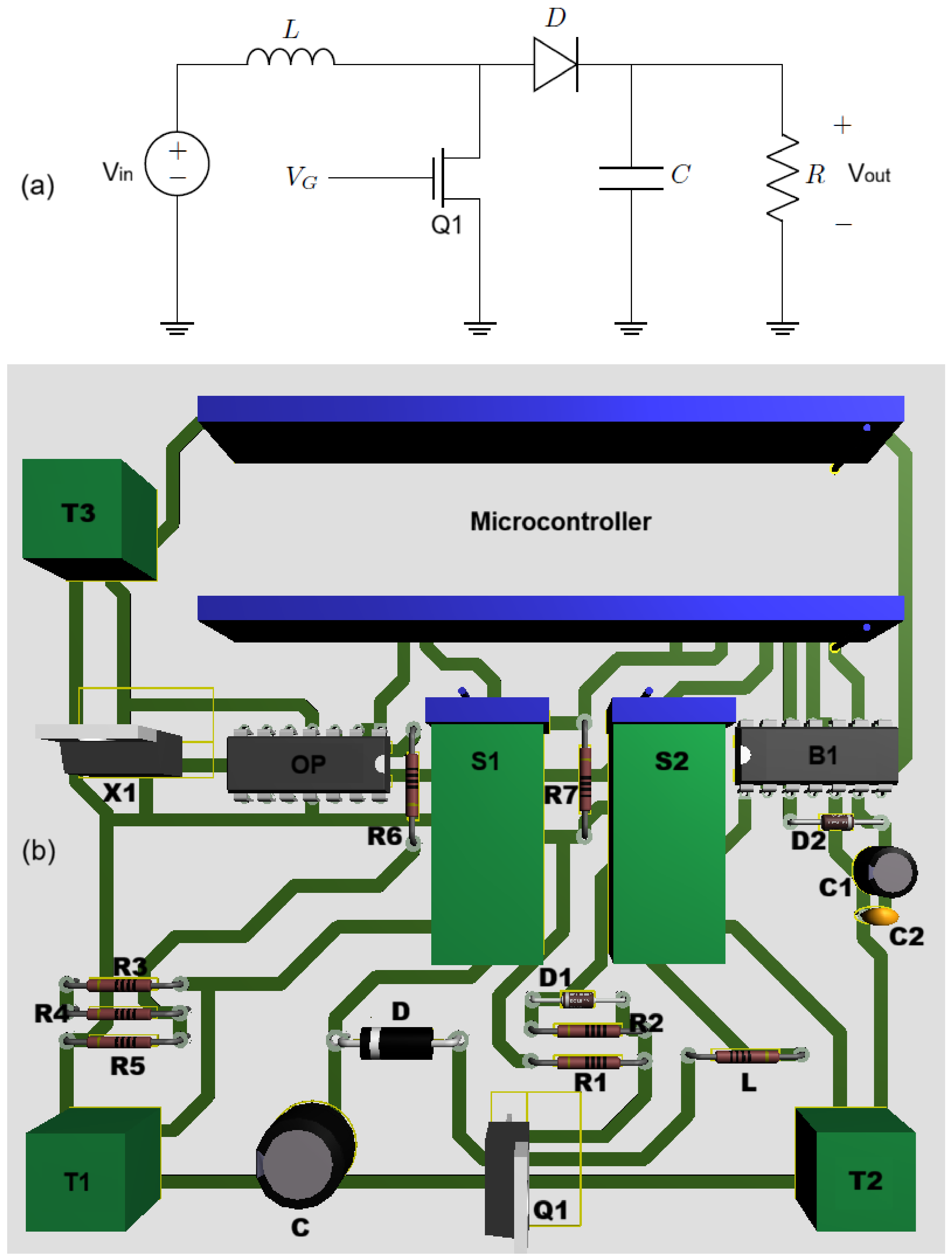
This section describes the electronic circuit and the main components employed to experimentally validate the controller gains obtained using the proposed tuning approaches. Figure 1a shows the schematic diagram of the boost converter, while Figure 1b presents the corresponding Printed Circuit Board (PCB) layout [24,25]. The developed board integrates the power-stage components of the boost converter together with the instrumentation circuits required to measure the electrical variables during the experimental tests [26].
The output voltage is measured using a voltage divider composed of resistors R 2 , R 3 , and R 4 , followed by a voltage buffer based on an operational amplifier. This configuration conditions the measured signal to the appropriate voltage level for the measurement system. Current sensing elements S 1 and S 2 are also incorporated to monitor the current during converter operation. Furthermore, connection terminals T 1 and T 2 allow the input voltage V i n and the load resistance R to be configured according to the experimental test conditions. This arrangement enables the converter to be evaluated under different input-voltage and load conditions.
A dedicated connector, T 3 , is used to supply the auxiliary instrumentation circuits and the gate-driver stage. The main switching device is an NMOS transistor, denoted by Q 1 , selected for its capability to operate at switching frequencies above 20 kHz and to withstand voltage and current levels higher than 100 V and 10 A, respectively. These characteristics are suitable for the operating conditions of the developed boost converter prototype [27,28].
The switching operation of the MOSFET is controlled by a digital Pulse-Width Modulation (PWM) signal, denoted by V G . PWM is used to control the switching state of the semiconductor device and, consequently, the energy transferred to the load [29,30,31,32,33,34]. In the developed prototype, the PWM signal is generated by a 32-bit ARM-based microcontroller at a switching frequency of 20 kHz.
A gate-driver circuit is used to interface the microcontroller with the MOSFET. The driver adapts the voltage level of the PWM signal to the level required for proper gate activation and provides electrical isolation between the control circuitry and the power stage. This configuration facilitates reliable switching operation and reduces potential interference between the control and power circuits [35].
The main components used in the experimental prototype are summarized in Table 1, including their corresponding symbols and nominal values.
The load resistors were evaluated separately to improve the reliability and accuracy of the experimental measurements. Testing multiple resistors simultaneously could introduce additional parasitic resistance associated with the connectors and interconnections, resulting in an equivalent load resistance that differs from the intended nominal value. Therefore, each load condition was tested independently to minimize these effects and ensure a more accurate representation of the specified load resistance.

3. Proposed Optimization Method

This section describes the procedure used to tune the PI controller applied to the boost converter. Two metaheuristic optimization algorithms, PSO and LPO, are employed to determine suitable combinations of the proportional ( K p ) and integral ( K i ) gains. The objective of the tuning procedure is to obtain controller parameters that provide an improved dynamic response under variations in the operating conditions of the converter. Each optimization algorithm was executed over multiple independent runs under the same simulation conditions to assess the consistency and robustness of the obtained solutions with respect to the inherent stochastic behavior of metaheuristic optimization. The results obtained using PSO and LPO were subsequently compared with those of a conventional PI controller whose gains were determined using the Root Locus method. The performance of the different controller configurations was assessed using an objective function that incorporates dynamic-response performance indicators. The optimization problem was formulated based on the mathematical model of the DC–DC boost converter. The transfer function to represent the dynamic behavior of the converter is given by:
G ( s ) = 1000 s + 2.5 × 10 6 s 2 + 250 s + 1.19 × 10 7
The objective function combines the settling time ( t s ) and overshoot (OS), thereby accounting for two key characteristics of the converter transient response. The settling time represents the time required for the output voltage to enter and remain within a specified tolerance band around the reference value, whereas the overshoot quantifies the maximum excursion above the reference. The optimization problem is therefore formulated as:
min K p , K i f ( K p , K i ) = w 1 · t s + w 2 · O S
For comparison purposes, a conventional PI controller was designed using the Root Locus method. The resulting proportional and integral gains were K p = 0.15609 and K i = 137.88 , respectively. In contrast, the optimization procedure based on PSO and LPO yielded the same controller gains under the conditions considered in the previous study, namely K p = 0.1 and K i = 300 . These gains were subsequently implemented in the experimental prototype described in the previous section to evaluate their performance under practical operating conditions. The experimental results obtained with these gains are compared with those obtained using the controller tuned through the Root Locus method. In summary, the controller gains obtained using the different tuning methods are presented in Table 2.

4. Optimization Criteria and Parameter Selection

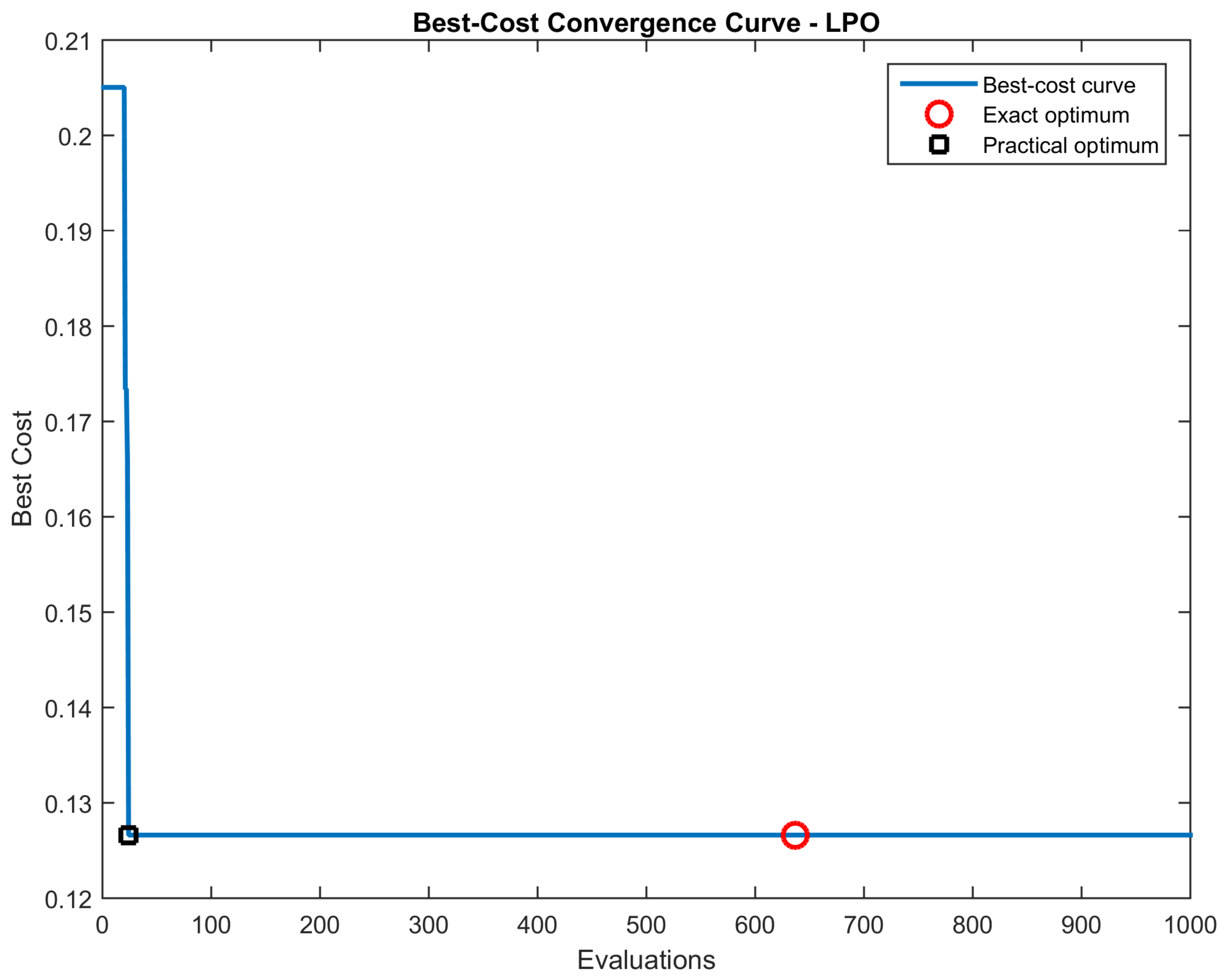
To determine the gain values of the controller, simulations were performed in a simulation environment using continuous-time models for both the boost converter plant and the PI controller in a closed-loop configuration. A reference voltage of 48 V and an input voltage of 12 V were considered, representing a typical operating condition of the boost converter. To ensure a consistent and unbiased comparison between the optimization algorithms, identical simulation and optimization conditions were established for PSO and LPO. A sensitivity analysis was conducted using maximum objective-function evaluation budgets of 300, 500 and 1000 evaluations, with 15 independent runs performed for each configuration. Fixed random seeds were used to ensure the reproducibility of the optimization results. The results showed that the average objective-function cost remained practically unchanged as the evaluation budget increased. For PSO, the average cost was identical for the three evaluation budgets, while LPO exhibited only minor variations that were considered negligible from a practical perspective. A similar trend was observed for the average settling time. In contrast, the average computational time increased as the number of objective-function evaluations increased. For PSO, the average execution time increased from 4.206 s for 300 evaluations to 7.041 s and 13.061 s for 500 and 1000 evaluations, respectively. For LPO, the corresponding execution times increased from 3.905 s to 6.476 s and 13.012 s. These results indicate that increasing the evaluation budget does not provide a significant improvement in the obtained solution while considerably increasing the computational cost. Therefore, 300 evaluations were selected as the reference configuration, providing an appropriate trade-off between solution quality and computational effort. In addition to the final optimization cost, convergence-related metrics were analyzed to characterize the evolution of the optimization process. For the purposes of this analysis, two indicators are defined. The “exact-optimum” denotes the average evaluation at which the minimum cost was reached in the optimization process. In contrast, the "practical-optimum" denotes the average evaluation at which the objective-function value falls within 0.001 of the best cost obtained during the optimization process. For PSO, the Exact optimum was reached, on average, at evaluation 126.4 for all three evaluation budgets. This value also coincided with the Practical optimum, indicating that the algorithm reached its best solution relatively early in the optimization process. For LPO, the Exact optimum was reached at later stages of the optimization, at evaluations 236.2, 440.0, and 629.47 for 300, 500, and 1000 evaluations, respectively. However, the Practical optimum was reached considerably earlier, at approximately evaluation 30.2 for all three configurations. This behavior indicates that, although LPO continues to refine the solution throughout the optimization process, a solution with practically equivalent performance is obtained during the initial stages of the search. Figure 2 illustrates the cost evolution and the relationship between the computational effort and the quality of the solution for the LPO algorithm using an evaluation budget of up to 1000 evaluations. As shown in the figure, the objective-function cost remains practically unchanged after the initial stages of the optimization. Although the minimum cost is reached at approximately evaluation 630, the difference between this solution and those obtained at considerably earlier evaluations is negligible. Based on this observation, the controller gains corresponding to the 300-evaluation configuration were selected as the reference solution for the subsequent analysis and experimental validation. Table 3 summarizes the main parameters used for the LPO and PSO optimization algorithms. The selected parameter values were adopted from the methodology described in our previous study [23].

5. Implementation and Validation in Simulation

This section evaluates the performance of the controller parameters obtained using analytical and metaheuristic tuning approaches through numerical simulations. Although the controller gains were originally optimized using a 48 V reference, subsequent simulation and experimental validation were performed on a 40 V reference because of the voltage-measurement limitation of the experimental platform. The input voltage was maintained at 12 V throughout the simulations. A single simulation run was performed for each controller configuration to evaluate the ability of the resulting gains to maintain output-voltage regulation under sequential changes in the load resistance. Instead of performing independent simulations for each operating condition, different load resistance values were introduced at predefined time intervals within the same simulation. This approach allows the dynamic response of the converter to be evaluated under successive load changes while maintaining the same controller parameters. Consequently, the effect of the load variations on the output voltage can be directly observed, providing a consistent assessment of the ability of each controller configuration to preserve voltage regulation under changing operating conditions.

5.1. Boost Circuit Simulation with Analytical Parameters

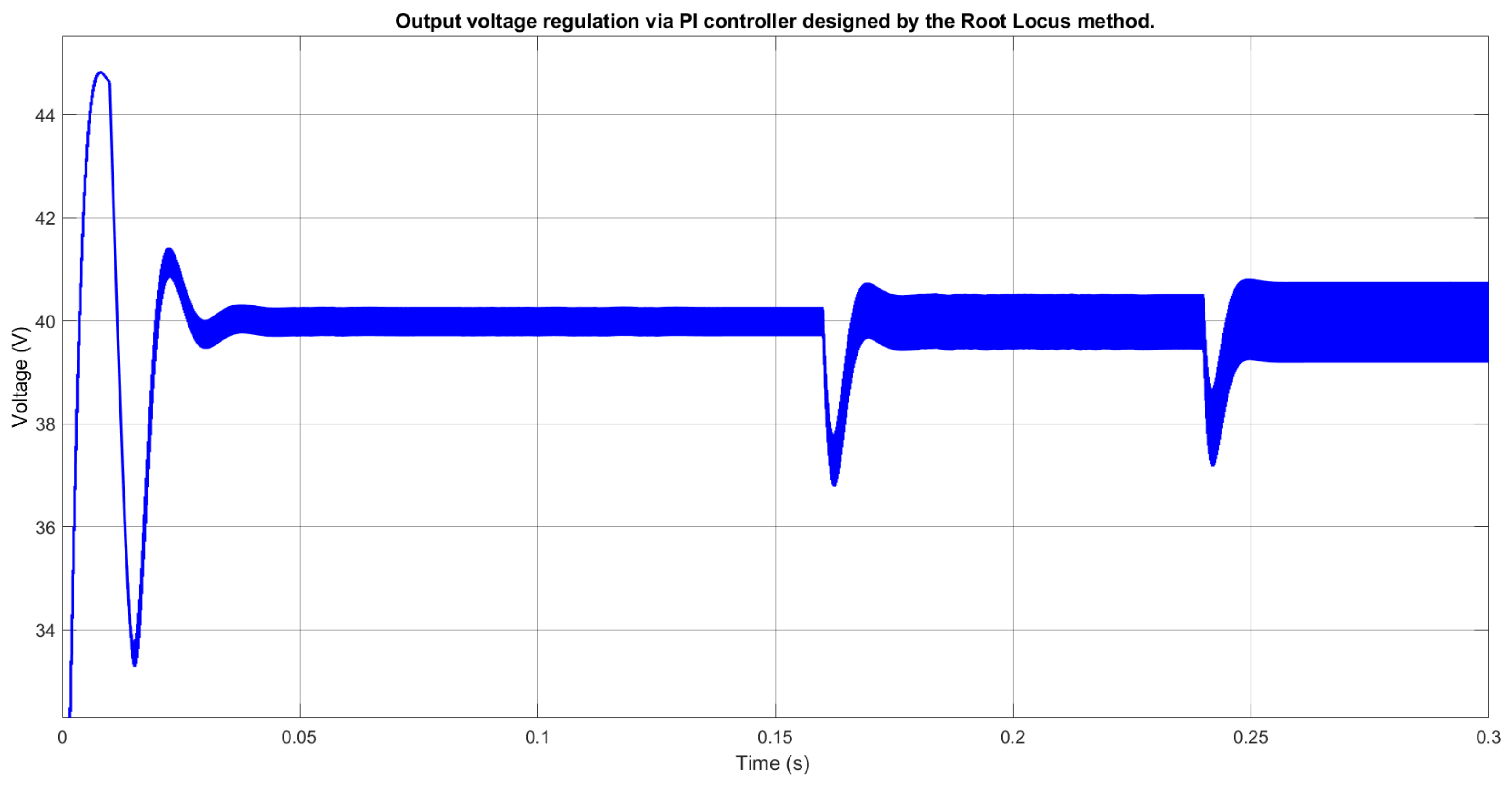
The first simulation was performed using the proportional and integral gains obtained through the Root Locus method, namely K p = 0.15609 and K i = 137.88 , as described previously. The converter was initially operated under no-load conditions. At t = 0.16 s, a load resistance of 10 k Ω was connected to the output. Subsequently, at t = 0.24 s, the load resistance was changed to 15 k Ω to introduce an additional operating disturbance. The resulting output-voltage response is shown in Figure 3.
The system reaches the reference voltage of 40 V, with a settling time of less than 0.02 s. During the initial transient, the output voltage varies between 33 V and 45 V. Following the connection of the load resistances, the output voltage remains within a range of approximately 36 V to 42 V. These results indicate that the controller maintains voltage regulation under the considered load variations.

5.2. Boost Converter Simulation with Metaheuristically Optimized Parameters

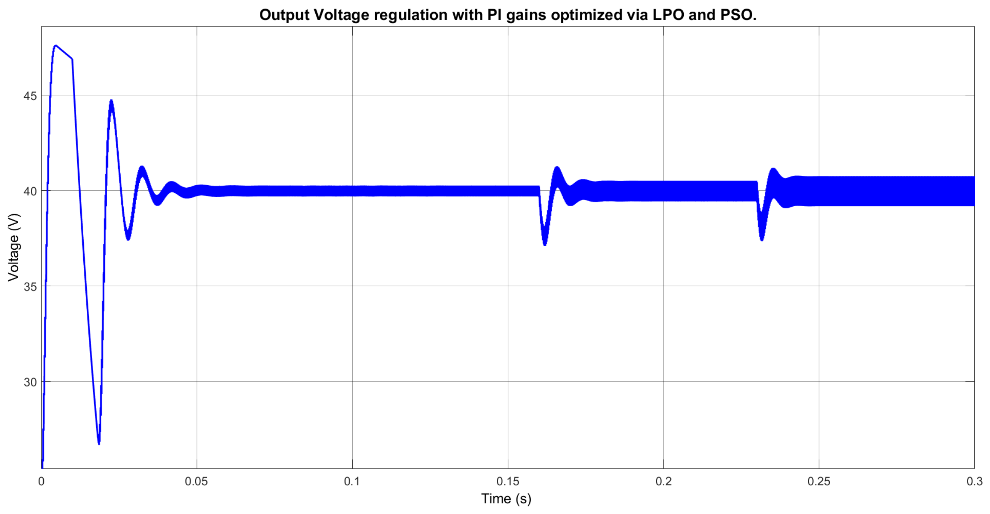
The second simulation was performed using the controller gains obtained through the PSO and LPO algorithms, namely K p = 0.1 and K i = 300 . Since both optimization algorithms converged to the same gain values under the conditions considered, a single simulation was performed using these parameters. The same operating conditions used for the Root Locus-based controller were maintained to enable a direct comparison. The converter initially operated under no-load conditions; at t = 0.16 s, a 10 k Ω load was connected, followed by a change to 15 k Ω at t = 0.24 s. The resulting output-voltage response is presented in Figure 4.
The output voltage reaches the reference value of 40 V with a settling time of approximately 0.02 s. Compared with the Root Locus-based controller, both approaches exhibit similar settling times under the considered conditions. However, the metaheuristic-based controller presents a higher initial overshoot, exceeding 45 V, corresponding to a deviation of approximately 5 V from the reference value. The minimum voltage during the initial transient is below 34 V. After the load transitions, the output voltage remains within approximately 37 V to 41 V. These results indicate comparable transient performance between the two tuning approaches, although differences in the magnitude of the initial transient response are observed.

6. Experimental Validation and Implementation

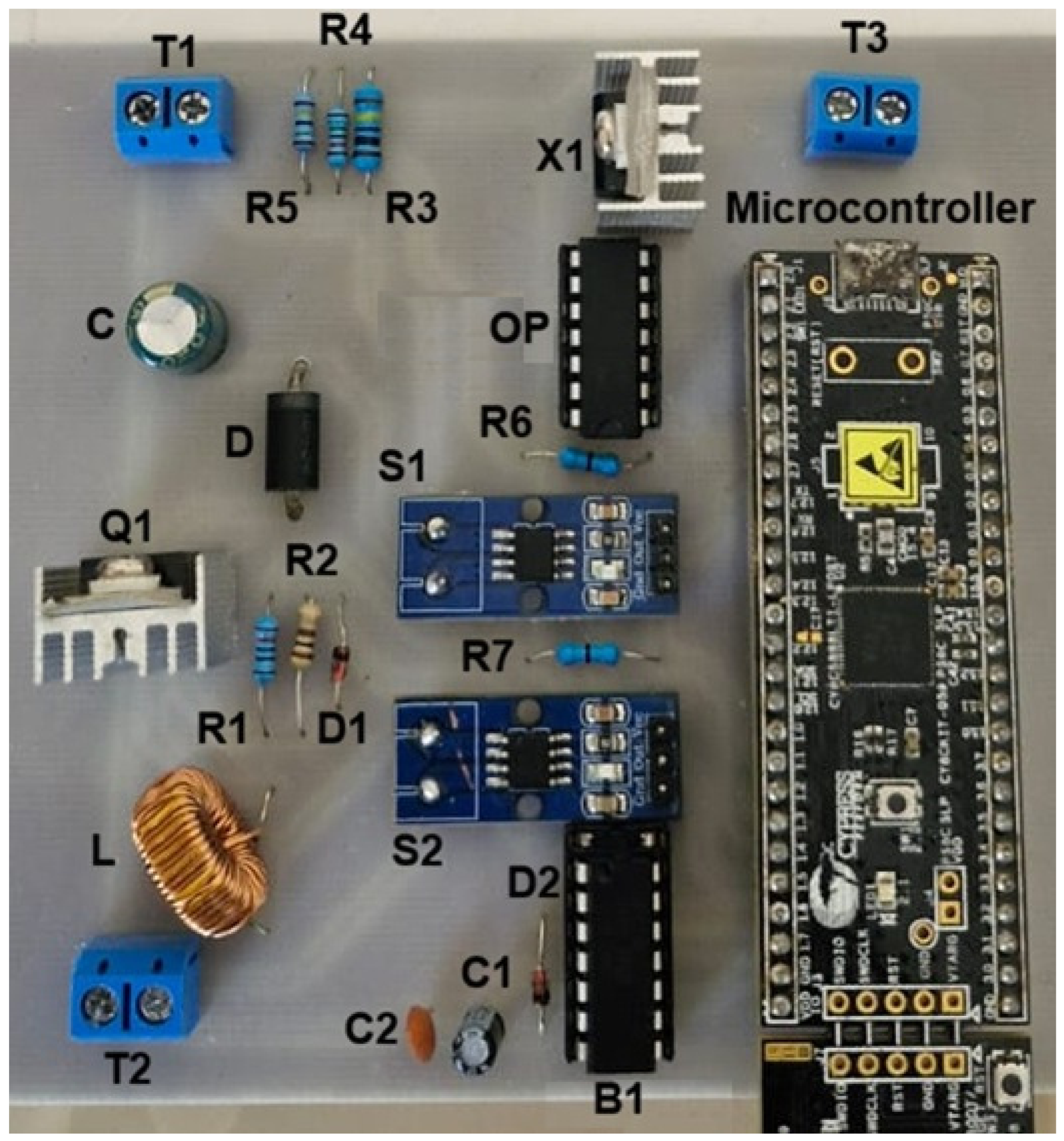
The boost converter prototype described in Section 2 was implemented for the experimental validation of the controller gains, as shown in Figure 5. During the experiments, terminal T 1 was connected to a 12 V power supply. The input voltage was intentionally subjected to unregulated variations in order to introduce disturbances into the converter and evaluate the response of the control system. Terminal T 2 was used to connect the resistive loads, whereas terminal T 3 supplied 15 V to the auxiliary circuits. The microcontroller generated the PWM signal at a switching frequency of 20 kHz.
To evaluate the controllers under practical operating conditions, controlled perturbations were applied to the input voltage, which was maintained below 30 V throughout the tests. The corresponding transient response of the converter output voltage was recorded using an oscilloscope. Experiments were conducted under three load conditions: no load, a 10 k Ω resistive load, and a 15 k Ω resistive load.
The results presented in the following subsections correspond to the transient interval following a perturbation in the input voltage. The analysis focuses on the ability of the controller to maintain output-voltage regulation and restore the output toward the reference value after the disturbance. A sampling frequency of 50 MHz was used for all experimental measurements. This sampling rate provided sufficient temporal resolution to capture the transient response associated with the input-voltage perturbations and to facilitate comparison between the Root Locus and metaheuristic tuning approaches.
The experimental evaluation of the metaheuristically optimized controller was performed using a single set of controller gains, since both PSO and LPO converged to identical gain values under the conditions considered. Consequently, the same controller gains were used to experimentally evaluate both optimization approaches.

6.1. Controller Gain Tuning via Root Locus Method

The first set of experimental results corresponds to the implementation of the PI controller gains obtained using the Root Locus method, K p = 0.15609 and K i = 137.88 .
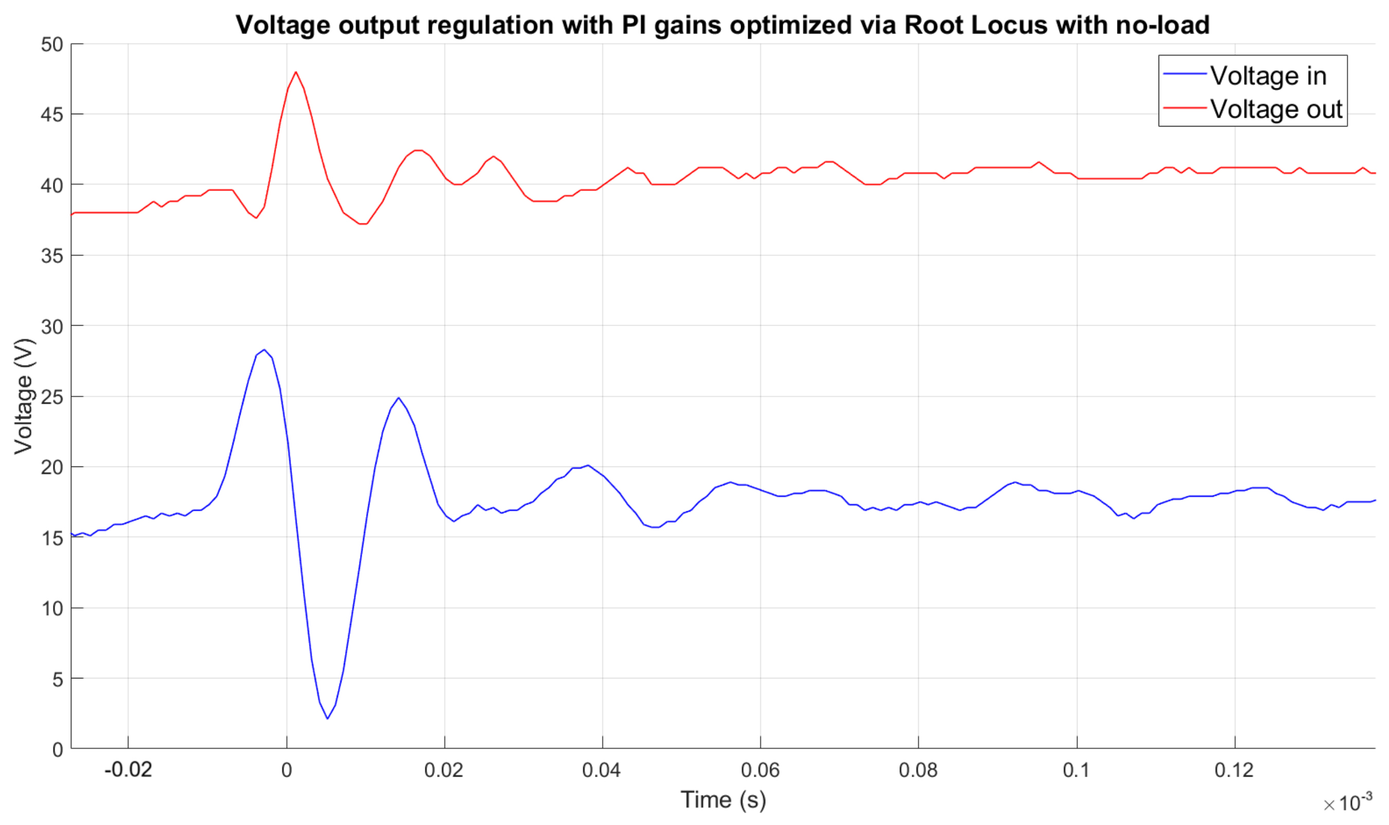
The dynamic response of the converter under no-load conditions following an input-voltage disturbance is shown in Figure 6. The input voltage, represented by the blue signal, varies throughout the measurement interval from t = 0.01 ms to t = 0.02 ms. The input voltage initially has a value of approximately 15 V, increases to 28 V at t = 0.005 ms, and subsequently decreases to approximately 2.5 V at t = 0.005 ms. The voltage then increases to approximately 25 V at t = 0.015 ms before returning to approximately 15 V at t = 0.02 ms.
The output voltage, represented by the red signal, remains regulated around the reference value despite the applied input-voltage disturbance. A settling time ( t s ) of approximately 0.03 ms is observed. The maximum output voltage reaches 47.5 V at approximately t = 0.002 ms, corresponding to a maximum deviation of approximately 7.5 V from the reference value. The minimum output voltage is approximately 37.5 V at t = 0.01 ms, corresponding to a deviation of approximately 2.5 V below the reference. The response demonstrates that the controller maintains output-voltage regulation despite the variations imposed on the input voltage.
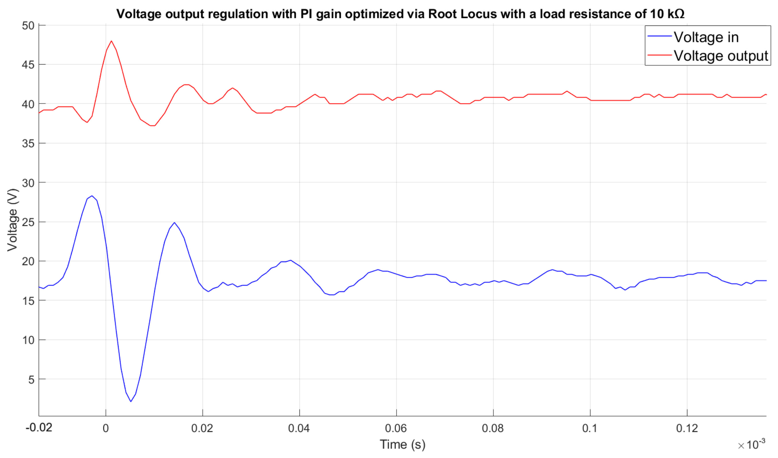
The response obtained with a 10 k Ω load is shown in Figure 7. The input voltage exhibits the same general disturbance profile, varying from approximately 15 V to 28 V, decreasing to 2.5 V, and subsequently returning toward its initial value. Under this condition, the output voltage remains regulated around the 40 V reference. The system exhibits a settling time of approximately 0.03 ms, while the maximum output voltage reaches approximately 48 V at t = 0.002 ms.
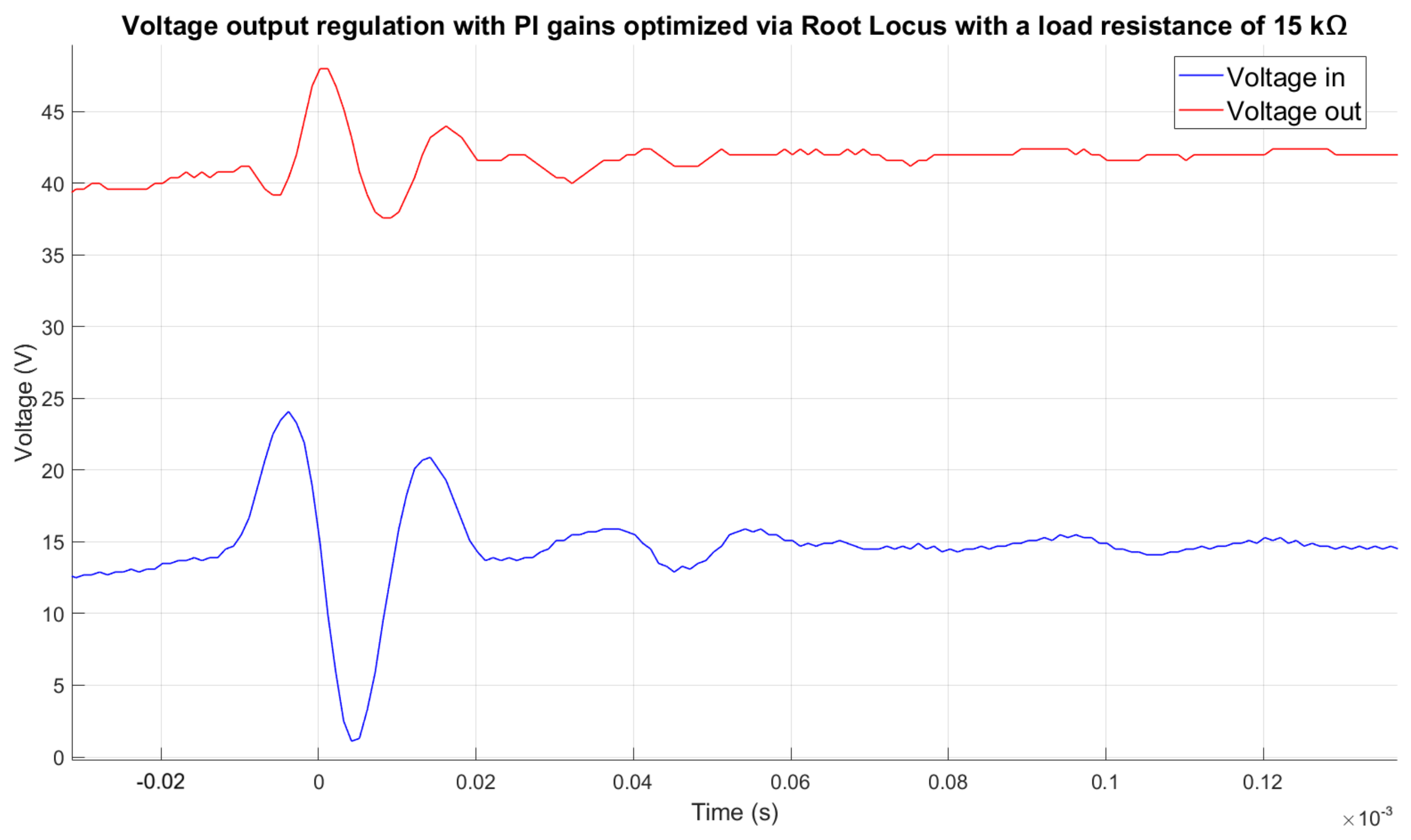
The response obtained with a 15 k Ω load under input-voltage disturbance is presented in Figure 8. In this case, the input voltage initially increases from approximately 15 V to 24 V, decreases to approximately 1.5 V, and subsequently increases to approximately 21 V before returning to its initial value. The output voltage remains regulated around the 40 V reference. The maximum output voltage reaches approximately 47 V, while the minimum value is approximately 37.5 V. These results indicate that the Root Locus-based controller maintains voltage regulation for both load conditions considered.

6.2. Controller Gain Tuning via Metaheuristic Parameters

The second set of experimental results corresponds to the implementation of the controller gains obtained using PSO and LPO, namely K p = 0.1 and K i = 300 . Since both optimization algorithms produced the same gain values, a single experimental evaluation was performed using this parameter set.
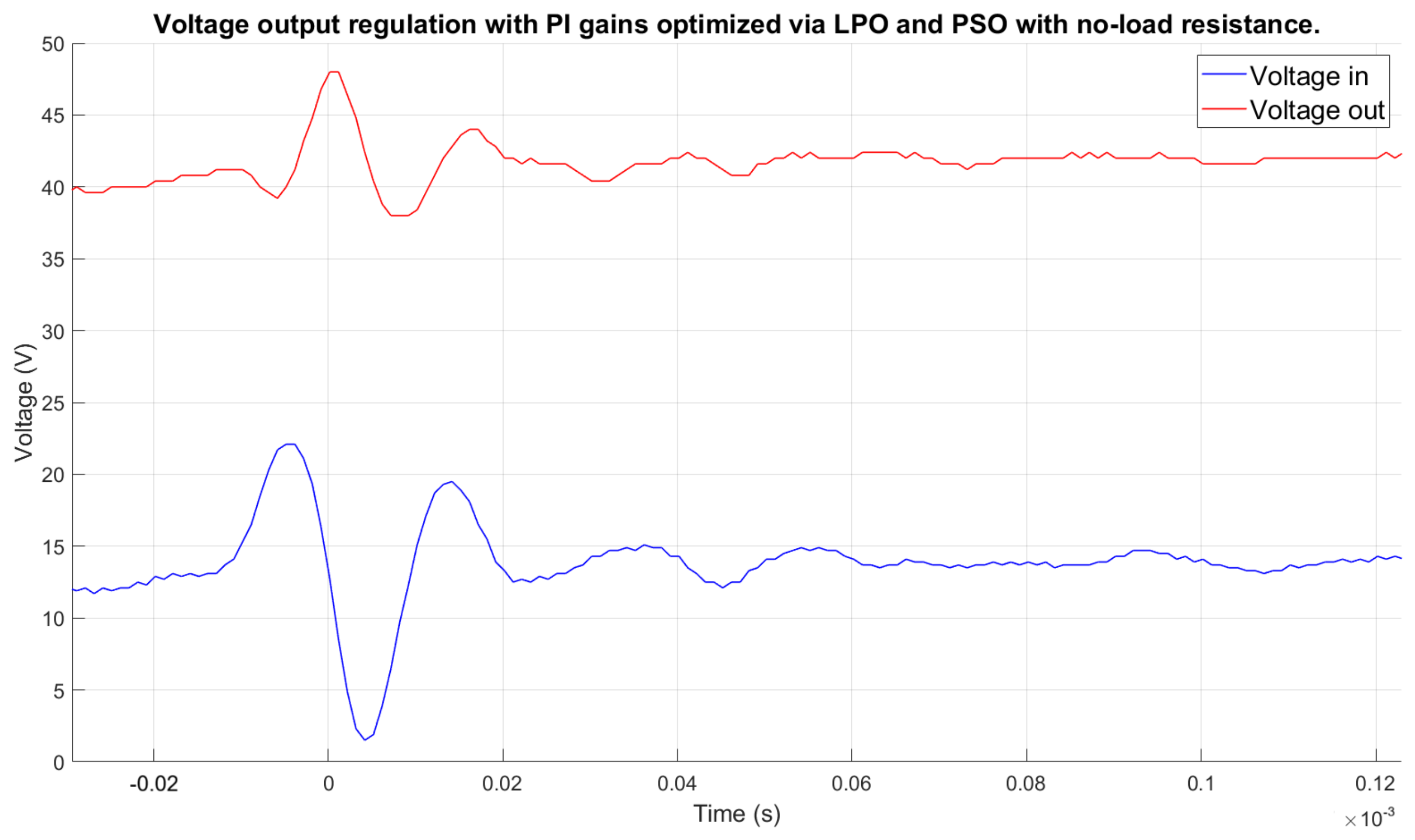
The dynamic response under no-load conditions is presented in Figure 9. The input voltage, represented by the blue signal, varies during the measurement interval. It initially reaches approximately 12 V, increases to approximately 22 V at t = 0.005 ms, and subsequently reaches approximately 19 V at t = 0.017 ms. The output voltage, represented by the red signal, remains regulated around the reference value. The settling time is approximately 0.03 ms, while the maximum output voltage reaches approximately 47 V at t = 0 ms.
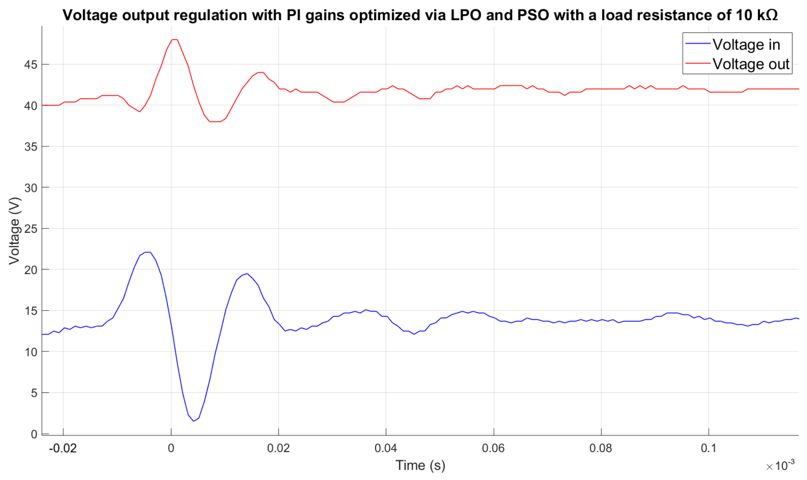
For the 10 k Ω load condition, the experimental response is presented in Figure 10. The input voltage varies during the interval from t = 0.01 ms to t = 0.02 ms, reaching approximately 22 V at t = 0.005 ms and approximately 19 V at t = 0.016 ms. The output voltage remains regulated around the 40 V reference, with a settling time of approximately 0.03 ms. The maximum output voltage reaches approximately 47 V at t = 0 ms.
Compared with the Root Locus-based controller under the corresponding load condition, the response exhibits similar settling behavior. However, the magnitude of the transient response differs due to the distinct input-voltage perturbation applied during the experimental test.
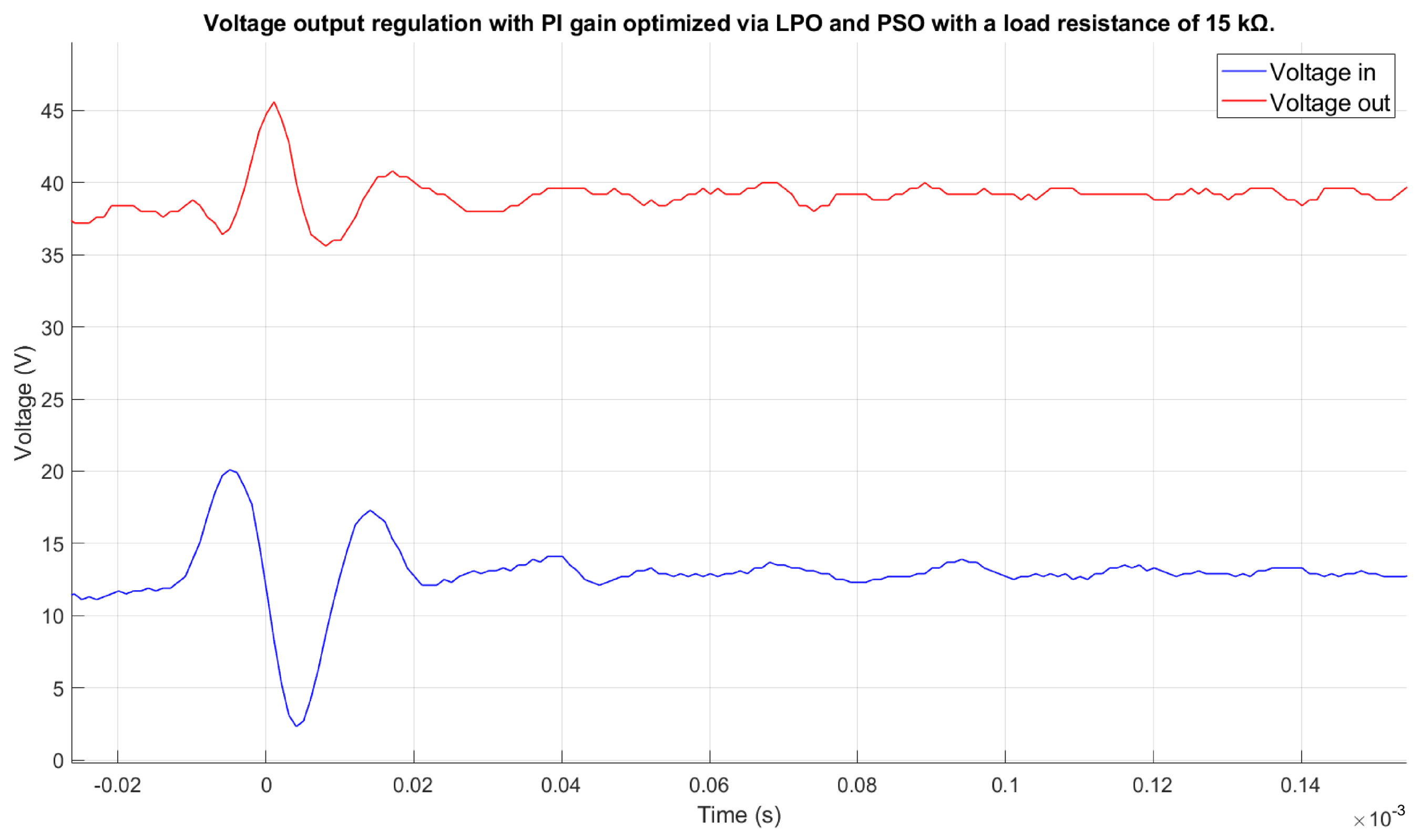
Finally, the response obtained with a 15 k Ω load is presented in Figure 11. The input voltage initially has a value of approximately 12 V, increases to 20 V at t = 0.005 ms, and subsequently reaches approximately 17 V at t = 0.017 ms. The output voltage remains regulated around the 40 V reference, with a settling time of approximately 0.03 ms. The maximum output voltage reaches approximately 45.3 V at t = 0.001 ms, while the minimum value is approximately 36 V at t = 0.01 ms.
Table 4 presents a comparative analysis of the experimental performance of the PI controller tuned using the Root Locus method and the metaheuristic optimization algorithms under different load conditions.

7. Conclusions

The experimental results demonstrate that the PI controller gains obtained using the metaheuristic optimization approaches, namely Lungs Performance Optimization (LPO) and Particle Swarm Optimization (PSO), provide dynamic responses comparable to those obtained using the conventional Root Locus method under the operating conditions considered. Although the three tuning approaches resulted in different controller gains, the corresponding controllers maintained output-voltage regulation in both the numerical simulations and the experimental prototype. In particular, the metaheuristic-based gains provided accurate convergence toward the reference voltage while maintaining stable operation under variations in input voltage and load resistance. The experimental results also show that the LPO- and PSO-based controllers maintained effective voltage regulation under the load conditions evaluated. Their responses exhibited limited voltage deviations following input-voltage disturbances, while the Root Locus-based controller showed comparatively larger transient variations under some of the tested conditions. These results indicate that the optimized gains obtained through the metaheuristic approaches can provide an adequate compromise between transient response and voltage regulation for the considered boost converter. A relevant aspect of the proposed approach is the consistency between the numerical and experimental evaluations. The controller gains obtained through the optimization process were successfully implemented in the physical prototype, and the experimental responses exhibited behavior consistent with the trends observed in the simulation. Furthermore, the analysis of the optimization process showed that a relatively low number of objective-function evaluations was sufficient to obtain practically optimal solutions, reducing the computational effort required to determine the controller parameters. Overall, the results support the use of metaheuristic optimization as an alternative approach for PI controller tuning in DC–DC boost converters. Under the operating conditions investigated, both LPO and PSO provided controller parameters that achieved stable voltage regulation and satisfactory dynamic performance. The experimental validation further demonstrates the feasibility of implementing the optimized gains in a physical converter, providing experimental evidence of the applicability of metaheuristic-based tuning methods to power electronic control systems.

Author Contributions

L.D.M.U. conceived and developed the proposed methodology, implemented the experimental setup, performed the analysis, and wrote the manuscript. V.M.R.R. contributed to conceptualization, experimental validation and data processing. D.A.U.S. contributed to software, methodological development and manuscript revision. B.S. supervised the research activities, validated the results, and reviewed the final manuscript. All authors have read and agreed to the published version of the manuscript.

Funding

This research received no external funding.

Institutional Review Board Statement

Not applicable.

Informed Consent Statement

Not applicable.

Data Availability Statement

The original contributions presented in this study are included in the article Further inquiries can be directed to the corresponding author.

Acknowledgments

The authors gratefully acknowledge the laboratory technicians at the Center for Scientific Research of Yucatán (CICY) for their valuable technical assistance. The authors also thank the administrative staff of CICY, especially Julia Gonzalez, for her administrative support throughout the development of this work.

Conflicts of Interest

The authors declare no conflicts of interest.

References

  1. Rai, I.; Suchetha, C. Microgrid and grid synchronization: A critical analysis of challenges and opportunities. Electr. Power Syst. Res. 2025, 242, e111434. [Google Scholar] [CrossRef] [Scilit]
  2. Blaabjerg, F.; Remus, T.; Liserre, M.; Timbus, A.V. Overview of control and grid synchronization for distributed power generation systems. IEEE Trans. Ind. Electron. 2006, 53, 1398–1409. [Google Scholar] [CrossRef] [Scilit]
  3. Abril, C.S.; Arias, R.; Guerrero, L.; González, L. Diseño de un convertidor elevador, para aplicaciones de energías renovables en instalaciones aisladas. Maskana 2014, 5, 99–108. [Google Scholar]
  4. Rabiaa, O.; Mouna, B.H.; Lassaad, S.A.; Aicha, A. Cascade Control Loop of DC-DC Boost Converter Using PI Controller. In Proceedings of the 2018 International Symposium on Advanced Electrical and Communication Technologies (ISAECT); Rabat-Kenitra, Morocco, 21–23 November 2018; pp. 1–5. [Google Scholar]
  5. Duong, M.Q.; Sava, G.N.; Scripcariu, M.; Mussetta, M. Design and simulation of PI-type control for the Buck Boost converter. Int. J. Eng. Trends Technol. 2012, 3, 71–73. [Google Scholar]
  6. Mahmoud, A.M.A.; Mashaly, H.M.; Kandil, S.A.; El Khashab, H.; Nashed, M.N.F. Fuzzy logic implementation for photovoltaic maximum power tracking. In Proceedings of the 9th IEEE International Workshop on Robot and Human Interactive Communication; IEEE ROMAN 2000 (Cat. No.00TH8499); IEEE: Piscataway, NJ, USA, 2000; pp. 155–160. [Google Scholar]
  7. Mitulkumar, R.D.; K.C., D. Analysis of Boost Converter Using PI Control Algorithms. Int. J. Eng. Trends Technol. 2012, 2, 71–73. [Google Scholar] [CrossRef] [Scilit]
  8. Sule, A.H.; Mokhtar, A.S.; Bin Jamian, J.J.; Khidrani, A.; Larik, R.M. Optimal tuning of proportional integral controller for fixed-speed wind turbine using grey wolf optimizer. Int. J. Electr. Comput. Eng. (IJECE) 2020, 10, 5251–5261. [Google Scholar] [CrossRef] [Scilit]
  9. Al-Dabbagh, Z.A.; Shneen, S.W.; Hanfesh, A.O. Fuzzy logic-based PI controller with PWM for buck-boost converter. J. Fuzzy Syst. Control 2024, 2, 147–159. [Google Scholar] [CrossRef] [Scilit]
  10. Kunjittipong, N.; Kongkanjana, K.; Khwan-on, S. Comparison of fuzzy controller and PI controller for a high step-up singleswitch boost converter. In Proceedings of the 3rd International Conference on Power and Energy Applications (ICPEA), Busan, South Korea, 9–11 October 2020; Volume 3, pp. 94–98. [Google Scholar]
  11. Özdemir, A.; Erdem, Z. Double-loop PI controller design of the DC-DC boost converter with a proposed approach for calculation of the controller parameters. Proc. Inst. Mech. Eng. Part I J. Syst. Control Eng. 2018, 232, 137–148. [Google Scholar] [CrossRef] [Scilit]
  12. Kennedy, J.; Eberhart, R. Particle swarm optimization. In Proceedings of ICNN’95—International Conference on Neural Networks; IEEE: Piscataway, NJ, USA, 1995; Volume 4, pp. 1942–1948. [Google Scholar]
  13. Sule, A.H. Studies of PID controller tuning using metaheuristic techniques: A review. Int. J. Innov. Sci. Eng. Technol. Res. 2022, 10, 44–63. [Google Scholar]
  14. Hussaian Basha, C.; Alsaif, F. A novel development of wide voltage supply DC–DC converter for fuel stack application with PSO-ANFIS MPPT controller. Sci. Rep. 2024, 14, e18826. [Google Scholar] [CrossRef] [Scilit] [PubMed]
  15. Thirumeni, M.; Thangavelusamy, D. Design and analysis of hybrid PSO–GSA tuned PI and SMC controller for DC–DC Cuk converter. IET Circuits Devices Syst. 2019, 13, 374–384. [Google Scholar] [CrossRef] [Scilit]
  16. Fermeiro, J.B.L.; Pombo, J.; Calado, M.; Mariano, S. A new controller for DC-DC converters based on particle swarm optimization. Appl. Soft Comput. 2017, 52, 418–434. [Google Scholar] [CrossRef] [Scilit]
  17. Aboura, F. Tuning PID Controller Using Hybrid Genetic Algorithm Particle Swarm Optimization Method for AVR System. In Proceedings of the 2019 International Aegean Conference on Electrical Machines and Power Electronics (ACEMP) & 2019 International Conference on Optimization of Electrical and Electronic Equipment (OPTIM), Istanbul, Turkey, 27–29 August 2019; pp. 570–574. [Google Scholar]
  18. Premkumar, K.; Vishnupriya, M.; Thamizhselvan, T.; Sanjeevikumar, P.; Manikandan, B.V. PSO optimized PI controlled DC-DC buck converter-based proton-exchange membrane fuel cell emulator for testing of MPPT algorithm and battery charger controller. Int. Trans. Electr. Energy Syst. 2021, 31, e12754. [Google Scholar] [CrossRef] [Scilit]
  19. Veerachary, M.; Saxena, A.R. Optimized power stage design of low source current ripple fourth-order boost DC–DC converter: A PSO approach. IEEE Trans. Ind. Electron. 2014, 62, 1491–1502. [Google Scholar] [CrossRef] [Scilit]
  20. Ghasemi, M.; Zare, M.; Zahedi, A.; Trojovskỳ, P.; Abualigah, L.; Trojovská, E. Optimization based on performance of lungs in body: Lungs performance-based optimization (LPO). Comput. Methods Appl. Mech. Eng. 2024, 419, 116582. [Google Scholar] [CrossRef] [Scilit]
  21. Wolpert, D.H.; Macready, W.G. No free lunch theorems for optimization. IEEE Trans. Evol. Comput. 2002, 1, 67–82. [Google Scholar] [CrossRef]
  22. Jafarnejad, G.E.; Masoud, R.A.; Nasih, Q. Service load balancing, task scheduling and transportation optimisation in cloud manufacturing by applying queuing system. Enterp. Inf. Syst. 2019, 13, 865–894. [Google Scholar] [CrossRef] [Scilit]
  23. Marín, L.; Ramírez, V.; Uribe, D.; Saldivar, B. Application of the LPO Algorithm to PI Controller Tuning: A Comparison with PSO in a Boost Converter. In Proceedings of the 2025 12th International Conference on Soft Computing & Machine Intelligence (ISCMI), Rio de Janeiro, Brazil, 21–23 November 2025; pp. 379–383. [Google Scholar]
  24. Martínez Mosquera, S.D.; Jiménez López, A.F. Diseño de Metodología para el Desarrollo de PCB Multicapa Siguiendo las Normas IPC2221; IPC: Singapore, 2016. [Google Scholar]
  25. Walker, A.D.; Williams, D. Thermal design considerations in the design and application of DC-DC converters. In Proceedings of the Applied Power Electronics Conference. APEC ’96, San Jose, CA, USA, 3–7 March 1996; IEEE: New York, NY, USA, 1996; Volume 2, pp. 990–996. [Google Scholar]
  26. Bang, D.H.; Park, J.Y. Ni-Zn ferrite screen printed power inductors for compact DC-DC power converter applications. IEEE Trans. Magn. 2009, 45, 2762–2765. [Google Scholar] [CrossRef] [Scilit]
  27. Kiran, B.R.; Ezhilarasi, G.A. Design and analysis of soft-switched Buck-Boost Converter for PV applications. In Proceedings of the 2015 Annual IEEE India Conference (INDICON); IEEE: Piscataway, NJ, USA, 2015; pp. 1–5. [Google Scholar]
  28. Siddhant, K.; Adil, U. Effective Design Analysis of a DC-DC Boost Converter with Experimental Validation. In Proceedings of the International Conference on Computation of Power Energy, Information and Communication (ICCPEIC), Chennai, India, 28–29 March 2018; pp. 28–29. [Google Scholar]
  29. Meptah, K.R.; Kahar, N. Power Converter Dual Functions Using Full Bridge Converter Controlled by Microcontroller Arduino. Prog. Eng. Appl. Technol. 2021, 2, 623–634. [Google Scholar]
  30. Prodic, A.; Maksimovic, D.; Erickson, R.W. Design and implementation of a digital PWM controller for a high-frequency switching DC-DC power converter. In Proceedings of the IECON’01. 27th Annual Conference of the IEEE Industrial Electronics Society (Cat. No.37243); IEEE: Piscataway, NJ, USA, 2001; Volume 2, pp. 893–898. [Google Scholar]
  31. Patella, B.J.; Prodic, A.; Zirger, A.; Maksimovic, D. High-frequency digital PWM controller IC for DC-DC converters. IEEE Trans. Power Electron. 2003, 18, 438–446. [Google Scholar] [CrossRef] [Scilit]
  32. Van Dijk, E.; Spruijt, J.N.; O’Sullivan, D.M.; Klaassens, J.B. PWM-switch modeling of DC-DC converters. IEEE Trans. Power Electron. 1995, 10, 659–665. [Google Scholar] [CrossRef] [Scilit]
  33. Liu, Y.; Sen, P.C. Digital control of switching power converters. In Proceedings of 2005 IEEE Conference; IEEE: Piscataway, NJ, USA, 2005; Volume 6, pp. 635–640. [Google Scholar]
  34. Priewasser, R.; Agostinelli, M.; Unterrieder, C.; Marsili, S.; Huemer, M. Modeling, control, and implementation of DC–DC converters for variable frequency operation. IEEE Trans. Power Electron. 2014, 29, 287–301. [Google Scholar] [CrossRef] [Scilit]
  35. Zhang, Z.; Fu, J.; Liu, Y.; Sen, P.C. Discontinuous-Current-Source Drivers for High-Frequency Power MOSFETs. IEEE Trans. Power Electron. 2010, 25, 1863–1876. [Google Scholar] [CrossRef] [Scilit]
Figure 1. (a) Boost converter schematic diagram, (b) PCB layout of the boost converter.
Sci 08 00250 g001
Figure 2. LPO cost evolution for 1000 objective-function evaluations, showing the Exact optimum and Practical optimum.
Sci 08 00250 g002
Figure 3. Output voltage response under load disturbances using a Root Locus-based PI controller.
Sci 08 00250 g003
Figure 4. Output voltage response under load disturbances using the PI controller with metaheuristically optimized gains.
Sci 08 00250 g004
Figure 5. Experimental setup for validation of the PI-based control algorithms.
Sci 08 00250 g005
Figure 6. Experimental response to an input-voltage disturbance under no-load conditions using the Root Locus-based PI controller.
Sci 08 00250 g006
Figure 7. Experimental response to an input-voltage disturbance with a 10 k Ω load using the Root Locus-based PI controller.
Sci 08 00250 g007
Figure 8. Experimental response to an input-voltage disturbance with a 15 k Ω load using the Root Locus-based PI controller.
Sci 08 00250 g008
Figure 9. Experimental response to an input-voltage disturbance under no-load conditions using the PI controller with PSO- and LPO-based gains.
Sci 08 00250 g009
Figure 10. Experimental response to an input-voltage disturbance with a 10 k Ω load using the PSO- and LPO-based PI controller.
Sci 08 00250 g010
Figure 11. Experimental response to an input-voltage disturbance with a 15 k Ω load using the PSO- and LPO-based PI controller.
Sci 08 00250 g011
Table 1. Components used in the experimental prototype.
ComponentSymbolValue
MosfetQ1
Driver circuitB1 (IR2110)
Load ResistanceR10–15 kΩ
InductorL100 μH
DiodeD
Electrolytic CapacitorC10 μF
Carbon film resistor 1/4 WR110 kΩ
Carbon film resistor 1/4 WR2100 Ω
Carbon film resistor 1/4 WR31 MΩ
Carbon film resistor 1/4 WR412 MΩ
Carbon film resistor 1/4 WR51.5 MΩ
Carbon film resistor 1/4 WR6, R70.1 Ω
Electrolytic CapacitorC122 μF
Multilayer Ceramic CapacitorC2100 nF
Fast Recovery DiodeD1, D2
Current SensorS1, S2
Operational AmplifierOP
Voltage regulatorX1
Table 2. Values of the gains obtained using the metaheuristic method and root locus methods.
GainRoot Locus MethodMetaheuristic Method
K i 137.88300
K p 0.156090.1
Table 3. Optimization Algorithm Parameters.
AlgorithmParameterValue
PSONumber of particles20
Inertia weight0.7298
Cognitive coefficient ( C 1 )1.49618
Social coefficient ( C 2 )1.49618
LPOPopulation size20
Number of inhalation–exhalation cycles ( N e )5
Table 4. Comparison of the experimental performance of the PI controller tuned using Root Locus and metaheuristic algorithms under different load conditions.
MethodLoadMaximum Input VoltageMinimum Input VoltageMaximum Output VoltageMinimum Output VoltageFinal Output VoltageMaximum OvershootUndershootFinal Deviation
(V)(V)(V)(V)(V)(%)(%)(%)
Root LocusNo-load 28.3 2.2 48.0 37.1 40.8 20.0 7.3 2.0
10 kΩ 28.2 2.2 48.0 37.2 41.0 20.0 7.0 2.5
15 kΩ 24.0 1.2 48.0 37.6 42.0 20.0 6.0 5.0
Metaheuristic algorithmsNo-load 22.0 1.5 48.0 38.0 42.0 20.0 5.0 5.0
10 kΩ 22.0 1.5 48.0 38.0 42.0 20.0 5.0 5.0
15 kΩ 20.0 2.5 45.5 36.0 39.0 13.8 10.0 2.5
Disclaimer/Publisher’s Note: The statements, opinions and data contained in all publications are solely those of the individual author(s) and contributor(s) and not of MDPI and/or the editor(s). MDPI and/or the editor(s) disclaim responsibility for any injury to people or property resulting from any ideas, methods, instructions or products referred to in the content.