1. Introduction
The indirect tensile test is an experimental test that is largely adopted to determine the tensile strength of brittle materials, both in the geotechnical field (specifically in the field of rock mechanics) and in the structural one (specifically in the field of cementitious materials). The test [
1,
2] was created and proposed by the Brazilian engineer Fernando Lobo Carneiro at the beginning of the 1940s to determine the tensile strength of concrete cylinders. The latter mechanical problem became necessary to evaluate the possibility of adopting concrete cylinders in place of steel ones for the repositioning of a historical church in Rio de Janeiro. The proposed test achieved resounding success at the international level, and since it was conducted
in by Lobo Carneiro, scientists began to refer to the indirect tensile test as the Brazilian test. Nowadays, this test is widely adopted in all international standards (see, e.g., [
3,
4,
5,
6]) and it plays a fundamental role in the evaluation of the mechanical characteristics of specimens obtained by suitable coring in existing structures. Mainly, this test is performed by compressing a cylindrical specimen along two opposite diametral generatrices. The break of the specimen occurs on the plane containing the loaded generatrices, due to tensile stresses orthogonal to that plane.
The ability of the Brazilian test to create a nonuniform stress field has been adopted in recent papers to identify the mechanical characteristics of anisotropic materials such as shale [
7] and fiber-reinforced cementitious materials [
8,
9], with the latter materials being of particular interest to both construction and extractive industries.
From a theoretical point of view, this problem has been faced by many authors, such as Timoshenko and Goodier [
10]. They analyzed the stress field in a circular disk subjected to two opposing concentrated forces applied to the circumference representing the disk contour. These results have been largely adopted in the literature (see, e.g., [
11,
12,
13,
14,
15,
16,
17]) to provide insights into the mechanical behavior of brittle and quasi-brittle materials. Other authors (see, e.g., [
18,
19]) proposed using numerical models for the evaluation of the stress field of a specimen under a Brazilian test.
Furthermore, Jemiolo [
20] identified the strain and displacement fields in both the assumptions of plane stress state and plane strain state. It is to be remarked that the displacement field obtained has been considered an ideal model without any kinematical constraint related to the real conditions of the specimen. The role of the contact between the plates of the testing machine and the specimen is discussed in many papers available in the literature (see, e.g., [
21,
22,
23,
24,
25,
26]), but this role is described with regard to its influence on the stress field rather than on the displacement one.
The Brazilian test has been recently (see, e.g., [
27,
28,
29,
30,
31]) adopted to carry out the experimental identification of some mechanical parameters (Young’ modulus and Poisson’s coefficient in addition to the tensile strength), starting from the theoretical model obtained in [
10], but the proposed approach takes into account only one component of the displacement, since the corresponding field is not completely known.
On the other hand, the identification process of the Brazilian test has improved greatly due to the development of full-field contactless displacement measurement techniques which, based on different approaches, measure the displacement of the points belonging to the cross-section of the specimen under test. It follows that the adoption of these techniques requires knowledge of the real displacement field acting on the specimen.
The real Brazilian test is performed by a testing machine that possesses a fixed platen and a moving one that applies a load or a displacement to the specimen. From a mechanical point of view, the experimental situation is in accordance with the theoretical one. From a kinematical point of view, on the contrary, the experimental situation is very different from the theoretical one usually considered, due to the absence of kinematical constraints. Indeed, the fixed platen imposes a null displacement on the lower generatrix of the specimen which is not present in the theoretical model. In recent decades, the development of ever-increasing computing power has allowed the development of a new field of scientific research related to numerical algorithms capable of modeling real problems for which the theoretical solution is not available and in wider application fields (see, e.g., [
32,
33]). Within these techniques, the so-called Finite Element Model approach has often played a fundamental role in the development of new theoretical solutions or in the improvement of existing ones.
In recent years, several authors have investigated the splitting (Brazilian) test both numerically and experimentally across various research domains. For instance, Jing et al. [
34] experimentally analyzed how the characteristics, particularly those related to fracture mechanisms, change in thermally treated granite specimens, identifying significant correlations between treatment temperature and fracture behavior. Zhang et al. [
35] explored the use of different resin types for repairing fractures in granite, aiming to enhance safety in subsurface engineering applications. They developed an improved specimen model that reduces asymmetries compared to the classical bi-material model. Li et al. [
36] and Kim et al. [
37] developed numerical models to study the fracture behavior of prismatic specimens subjected to the Brazilian test with supporting fixtures, using image processing techniques and a phase-field fracture model, respectively. Furthermore, Lei et al. [
38] proposed a numerical model for shale specimens, building on Rocco’s theoretical framework [
39], and incorporating void and defect distributions characterized by CT-scan imaging. None of the aforementioned studies calculated the mechanical properties of the materials based on measured displacements, likely due to the focus on heterogeneous mate-rials, where standard theoretical approaches are not easily applicable and assumptions such as symmetry across the loading axis cannot be strictly satisfied.
The present paper aims to define a new constitutive relation for homogeneous isotropic materials by means of a suitable FEM of the Brazilian splitting test. In particular, a kinematical model of the Brazilian test in real conditions is considered, and the obtained numerical results allow us to gather information on the mechanical behavior of the material. The goal is achieved by starting with the actual model available in the literature and integrating it by adopting the results obtained by numerical simulations performed by ANSYS 2021 R1 software. The numerical simulations have been performed by adopting a wide range for both geometrical and mechanical characteristics; these ranges have been identified considering the regulatory indications as well as the materials (concrete and rocks) usually tested. On the grounds of the obtained results, a new formula that is able to relate the displacement field to the Young’s modulus is proposed, and this opens up new and interesting perspectives on the development of identification techniques to determine other mechanical characteristics of the material besides the tensile strength.
2. Materials and Methods
In this section, the approach adopted for the determination of the mechanical behavior of the isotropic material using the Brazilian splitting test is presented. The first subsection reports the basis of the Brazilian splitting test, the solution in terms of stresses available in the literature, and the consequent strain and displacement solutions. The second subsection describes the FEM for the simulation of a real Brazilian splitting test.
2.1. Brazilian Test
The splitting test (see
Figure 1), also known as the Brazilian splitting test [
1,
3,
4,
5], is an internationally adopted, effective test for determining the indirect tensile behavior (usually the strength) of brittle materials such as rocks and cementitious ones. The test is performed by placing a cylindrical specimen of known geometrical characteristics (diameter
and depth
) between the plates of the testing machine. A uniformly distributed load
is applied on the upper generatrix by the upper platen until the sample is broken.
Initially, contact between the platen and the specimen is produced in a unique contact line. Because of the finite elastic moduli of the involved materials, increments in the load application during test execution cause contact to evolve from a line to an area. Although the specimens are straight cylindrical elastic solids, the analytical approach to the problem can be stated in terms of plane elasticity if the contact stresses are uniformly distributed along the longitudinal direction [
2]. Hence, a three-dimensional elastic problem is usually converted into a two-dimensional problem, simplifying its mathematical treatment.
In the literature [
11], the general case of a disk subjected to a couple of opposite concentrated forces
acting along a chord has been studied and the corresponding stress field has been determined under the assumptions of perfectly elastic material. In this framework, the case of the cross-section of a specimen composed of homogeneous linear elastic material subjected to the Brazilian splitting test can be regarded as a special case in which the chord coincides with the vertical diameter (
Figure 2) and
.
The stress, strain, and the corresponding displacement fields arising in the specimen under the test are three-dimensional. However, depending on the ratio between depth and diameter,
, the further assumption of plane stress state or plane strain state can be assumed. In the former case, the stress field is given by the following relation [
20]:
where
. In the case of plane strain state, the following relations hold:
In [
20], the analytical expression for
in the case of plane stress state or that for
in the case of plane strain state can be found.
Considering the mathematical definition of
and
, by integration of Equations (3a) and (3b), and considering Equation (3c), the following equations for the displacements
(along the
-axis) and
(along the
-axis) are obtained:
In Equations (4) and (5),
and
are unknown functions to be determined by imposing suitable boundary and symmetry conditions, while the parameter
has been introduced to obtain a unique formula for both the cases of plane stress and plane strain states (
for plane stress state;
for plane strain state) [
20]. Both the geometrical symmetry and the mechanical one with respect to the
-axis lead to the consequence that
Furthermore, considering Equations (3c), (4) and (5), the following relation is obtained:
which, because of Equation (6), leads to
By comparing
Figure 1b and
Figure 2, it is evident that the theoretical model shows a double symmetric kinematical condition (either along the
-axis or the
-axis). Consequently, in the theoretical model, the result is as follows:
Equation (9a) is valid only in the theoretical model but not in the real condition. It follows that, to characterize the kinematical behavior observed during the Brazilian test, it is necessary to determine (see Equation (4)) , which represents the displacement along the -axis of the points belonging to the -axis; this goal is performed by adopting a suitable numerical approach based on the FEM described in the following subsection.
2.2. Numerical FEM
The determination of the constant in Equation (8) cannot be mathematically determined, since all the quantities involved diverge at points A and B. It follows that to characterize the kinematical behavior under the Brazilian splitting test, it is necessary to refer to numerical simulations. The latter have been performed in the ANSYS 2021 R1 Workbench environment, under the hypothesis of linear elastic behavior of the involved materials, by varying the geometrical parameters, the distributed force
and the Young’s modulus, recording the
-displacement along the
-axis. The Poisson’s coefficient has been initially assumed to be
and its influence has been checked by repeating the analyses, assuming
, as reported at the end of
Section 3.
In order to reproduce the real Brazilian test, the numerical model geometry accounts for both the specimen under testing as well as for the presence of two steel plates (
,
; see
Figure 3a): one devoted to imposing the kinematical full-restrained constraint on the lower generatrix of the specimen, while the other focuses on applying the distributed load on the upper generatrix of the specimen. The presence of the plates implies the modeling of the contact between the plates and the specimen, which we will describe in this paper. The adopted elements are 10-node isoparametric elements for solid discretization and 8-node 3D solid contact elements for surface-to-surface contact modeling. All the contacts have been modeled as “bonded”, as penetration and gaps are not allowed. The large deformation option is set to improve convergence in cases with low stiffness. All analyses have been nonlinear due to contact, but convergence has been gained in a few iterations.
The mesh dimension was selected after suitable preliminary mesh independence investigations that aimed to find the best compromise between results and computational time. This study has been performed by adopting the model with the highest diameter for the cylinder and the lowest Young’s modulus value for material stiffness. The final mesh (
Figure 3b) leads to a displacement value within 2% of that obtained by doubling the number of elements, presenting about 107,000 elements in total, and all the analyses have the same element distribution. To reduce the computational effort, the geometric numerical model takes into account the symmetry of the real problem. Therefore, the adopted boundary conditions are as follows: (a) symmetry in the vertical diametral faces; (b) fixed support (all displacements are equal to zero) on the lower face of the lower platen (plane B in
Figure 3a); (c) surface-distributed force on the upper face of the upper platen (plane A in
Figure 3a), and all contact modeled as bounded.
The steps performed in the numerical analyses are summarized here, while the values of the selected parameters are reported in the following section. For the assigned depth-to-diameter ratio () and for the selected value of Young’s modulus , the specimen diameter was varied within the selected range. For each configuration, the corresponding distributed force applied to the upper plate was calculated based on a prescribed pressure acting at the center of the specimen, as indicated by the relevant international standards. During each simulation, the horizontal displacement u along the specimen’s diameter was recorded and verified to remain effectively constant, with deviations from the mean value remaining below 1%.
3. Results
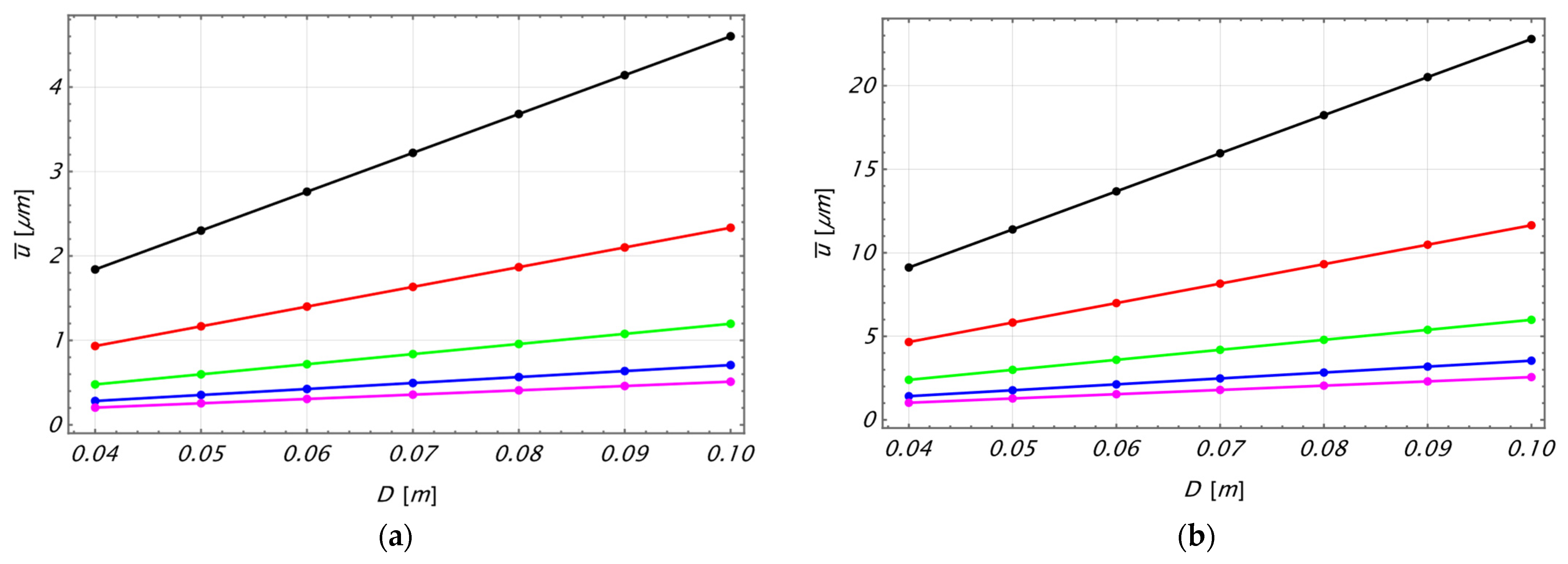
The analyses reported in this section have been performed with particular focus on the case, as prescribed by international standards, of the ratio between depth and diameter
, by varying the Young’ modulus in the range
and the diameter in the range
with increments equal to 0.01 m. The main idea is to perform the analyses in such a way that the stress acting at the center of the specimen is considered as constant. The relation between this stress (indicated as
below) and the total acting force is reported in all international standards, and it is given by
The acting force has been determined assuming that is in the range of . The assumed values have been selected considering that the Brazilian test is usually performed for rocks and concrete samples.
The results, in terms of displacement
vs. the diameter
, are reported in the following
Figure 4.
From an examination of
Figure 4, it can be stated that the displacement
is a linear function of the diameter
and that the slope
of the lines is a function of both the Young’s modulus and
; that is,
The expression of the function
in Equation (11) must be defined. Since the slope is dimensionless, to check the evolution of the function
, it is straightforward to plot it vs. the ratio
, as reported in
Figure 5.
An examination of
Figure 5 indicates that the slope
is a linear function of the ratio
. In
Table 1, the values of the slope, determined by the LinearModelFit command available in Mathematica
® 14.1 library, are reported.
The examination of
Table 1 clearly indicates that the difference between the values of the slope in the first and last case is less than 4%, which can be ascribed to numerical uncertainty. Therefore, the slope’s value is herein assumed as a constant and equal to the mean value 2.2695. Assuming this value as the reference one, the error lies in the range
. To check the possible influence of the Poisson’s coefficient on the results, the numerical simulations have been repeated assuming
, and the obtained results are reported in
Table 2.
The obtained results are 1% greater than those present in
Table 1; therefore, it can be deduced that the value of the slope
is almost independent of the Poisson’s coefficient.
The above remarks indicate that the displacement
can be obtained by
where
. The final Equation (12) has been derived considering that the numerical investigations have been performed for
, as already stated at the beginning of
Section 3.
4. Discussion
The results presented in the foregoing section represent a conclusive step toward understanding the kinematical and mechanical behavior of a specimen of homogeneous isotropic material subjected to the Brazilian test. The obtained results show that the vertical displacement of the horizontal diameter is constant, and it depends linearly on the pressure acting on the horizontal diametral plane of the specimen and inversely on the Young’s modulus. Similarly, the acting pressure linearly depends on the acting load and inversely on the diameter; as a consequence, on the whole, the vertical displacement linearly depends on the acting load and inversely on both the diameter and the Young’s modulus. This result is physically meaningful, since for a specimen with assigned geometry and material, an increasing load clearly increases the vertical displacement. On the other hand, for an assigned load, the vertical displacement decreases for an increment of the diameter and/or of the Young’s modulus. The most notable new result is the evaluation of the constant factor
specializing the relation among the above-described quantities. This result is a novelty, since no other study available in the literature faced the proposed problem leading to an explicit relation as obtained in the foregoing section. Another result is the independence of the considered displacement
on the Poisson’s coefficient of the material. The latter result is coherent with the theory of isotropic material, in which the Poisson coefficient influences only the kinematical behavior in a transverse direction. The above-reported results can be compared with the corresponding ones arising in a prismatic specimen (square cross-section of side
and depth
, which is a prismatic specimen circumscribed to the cylindrical of the Brazilian splitting test) subjected to a standard compression test. In this case, the theoretical solution leads to the following relation for the vertical displacement of the midplane
where the latter part of Equation (13) is obtained under the assumption of
. The comparison between Equations (12) and (13) leads to the remark that, under the same total load
, the displacement
is greater in the case of Brazilian splitting test. This result must be ascribed to the difference in the geometry of the two specimens, which leads to different stress and strain fields with the described consequence on the displacement
.
5. Conclusions
In this study, the behavior of cylindrical specimens composed of homogeneous and isotropic material subjected to the Brazilian splitting test is investigated through the development of appropriate finite element models implemented within the ANSYS environment. Numerical simulations were carried out assuming a depth-to-diameter ratio equal to 2, in accordance with relevant international standards. These standards, together with the assumption of material homogeneity and isotropy, constitute the sole constraints of the present investigation.
The theoretical framework available in the literature is well established, with the exception of the constant value of displacement, which is aligned to the loading direction along the diameter orthogonal to the loading direction. The results obtained in this study enable (1) the determination of this displacement constant, thereby completing the theoretical model; and (2) the characterization of its dependence on the specimen’s geometric parameters (diameter ), mechanical properties (Young’s modulus and Poisson’s ratio ), and the applied load intensity . Specifically, the displacement was found to exhibit a linear relationship with the specimen diameter , where the slope of this linear trend is a function of both Young’s modulus and the applied stress.
Moreover, the outcomes of the numerical analysis led to the formulation of an explicit equation that can be employed for the identification of the mechanical properties of a given material—under the assumption of homogeneity and isotropy—using full-field, contactless measurement techniques such as Digital Image Correlation (DIC) and/or Electronic Speckle Pattern Interferometry (ESPI).
Future work will focus primarily on the analysis of specimens with varying ratios and the experimental validation of the proposed model through an extensive testing campaign.


