
Design and Implementation of a Comparative Study of Fractional-Order Fuzzy Logic and Conventional PI Controller for Optimizing Stand-Alone DFIG Performance in Wind Energy Systems

 , , ,
, , ,
Abstract
1. Introduction

| Control Method | Pros | Cons | Related Work |
|---|---|---|---|
| PI Controller | -Simple, widely used, easy to implement |
-Not suitable for nonlinear processes -Sensitive to operating conditions and parameter variations -Poor dynamic response | [14] |
| SMC | -Effective for nonlinear systems | -Requires an accurate mathematical model. | [16] |
| MRAC | -Suitable for nonlinear processes and uncertainties |
-Computationally extensive/expensive. -Requires plant model/information | [20] |
| FLC | -Handles nonlinearities and uncertainties. |
-Requires expert knowledge -Expensive hardware implementation -Limited performances (non-adjustable dynamics) | [23] |
| Simplified rule FLC | -Suitable for complex and nonlinear processes | -Affected by external disturbances | [37] |
| Single-input FLC | -Simpler structure | -Reduced dynamic performance | [38] |
| Self-tuning FLC-PI | -High performance with nonlinear systems | -Expensive hardware implementation | [39] |
| Probabilistic fuzzy neural network (PFNN) |
-High performance with nonlinear systems -Computationally efficient | -Difficult development and tuning of neural networks | [40] |
| Takagi–Sugeno FLC (TS-FLC) |
-Suitable for nonlinear systems -Computationally efficient | -Requires expert knowledge | [15] |
| Proposed FOFLC |
-More flexible structure (adjustable dynamics) -Simple tuning without structural changes -High performance with nonlinear systems | -Requires additional computation |
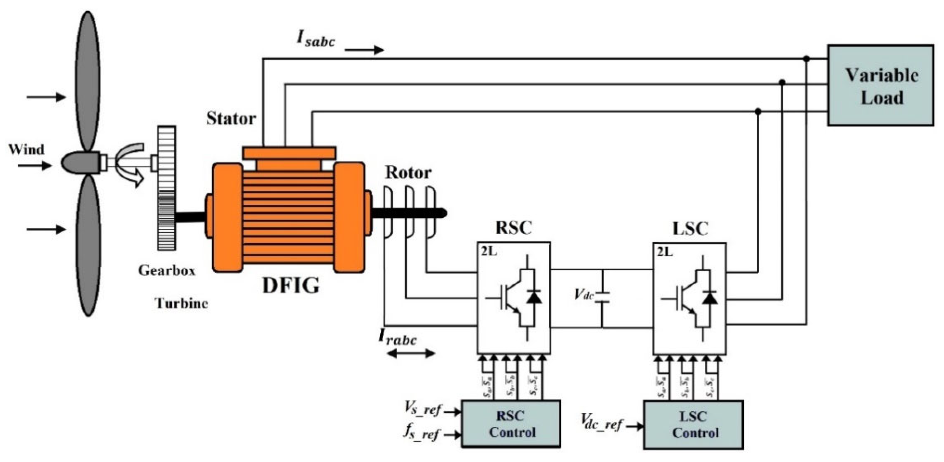
2. Configuration of Stand-Alone DFIG System
3. Modeling and Field Oriented Control of Stand-Alone DFIG
3.1. Modeling of DFIG
- Stator and rotor voltages in d-q frame:
- Stator and rotor fluxes in d-q frame:
- The expression for the electromagnetic torque is:
- The active and reactive stator power equations in the d-q-axis are as follows:
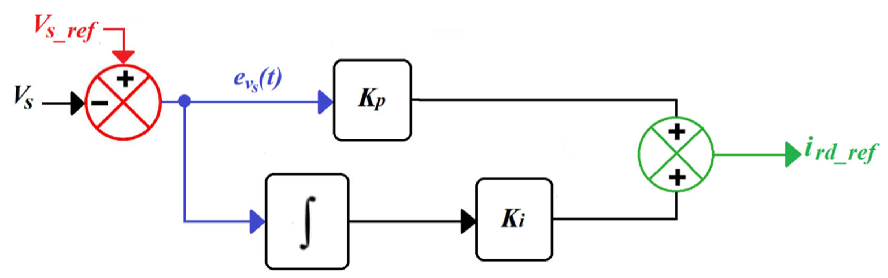
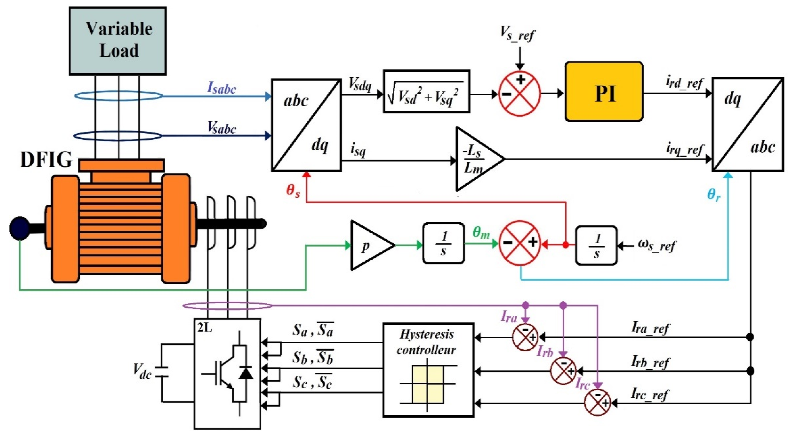
3.2. Field Oriented Control of Stand-Alone DFIG
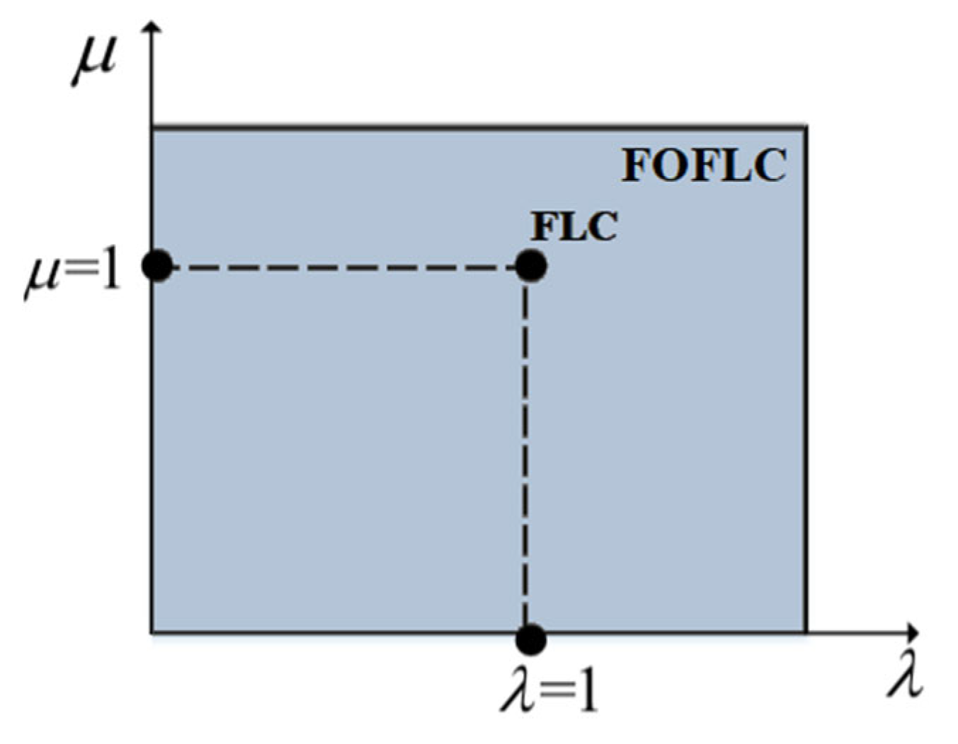
4. Fractional-Order (FO) Approach
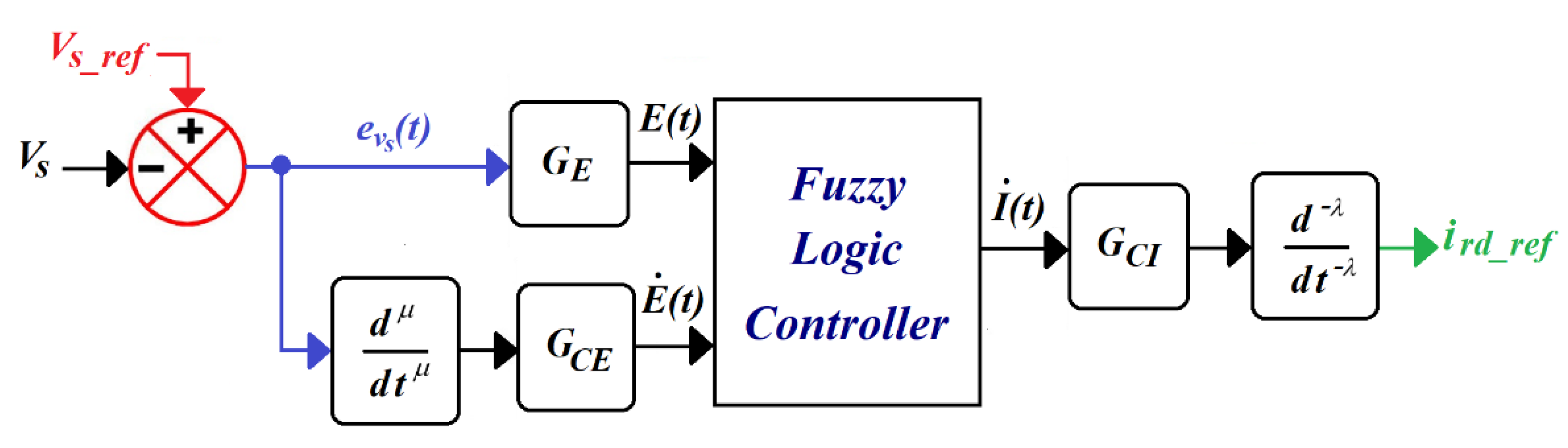
5. Fractional-Order Fuzzy Logic-Based Stator Voltage Control
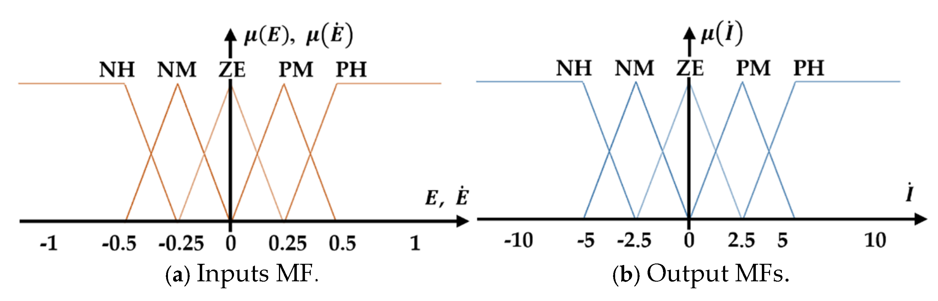
5.1. Fuzzy Logic Technique Design
5.2. Numerical Solution
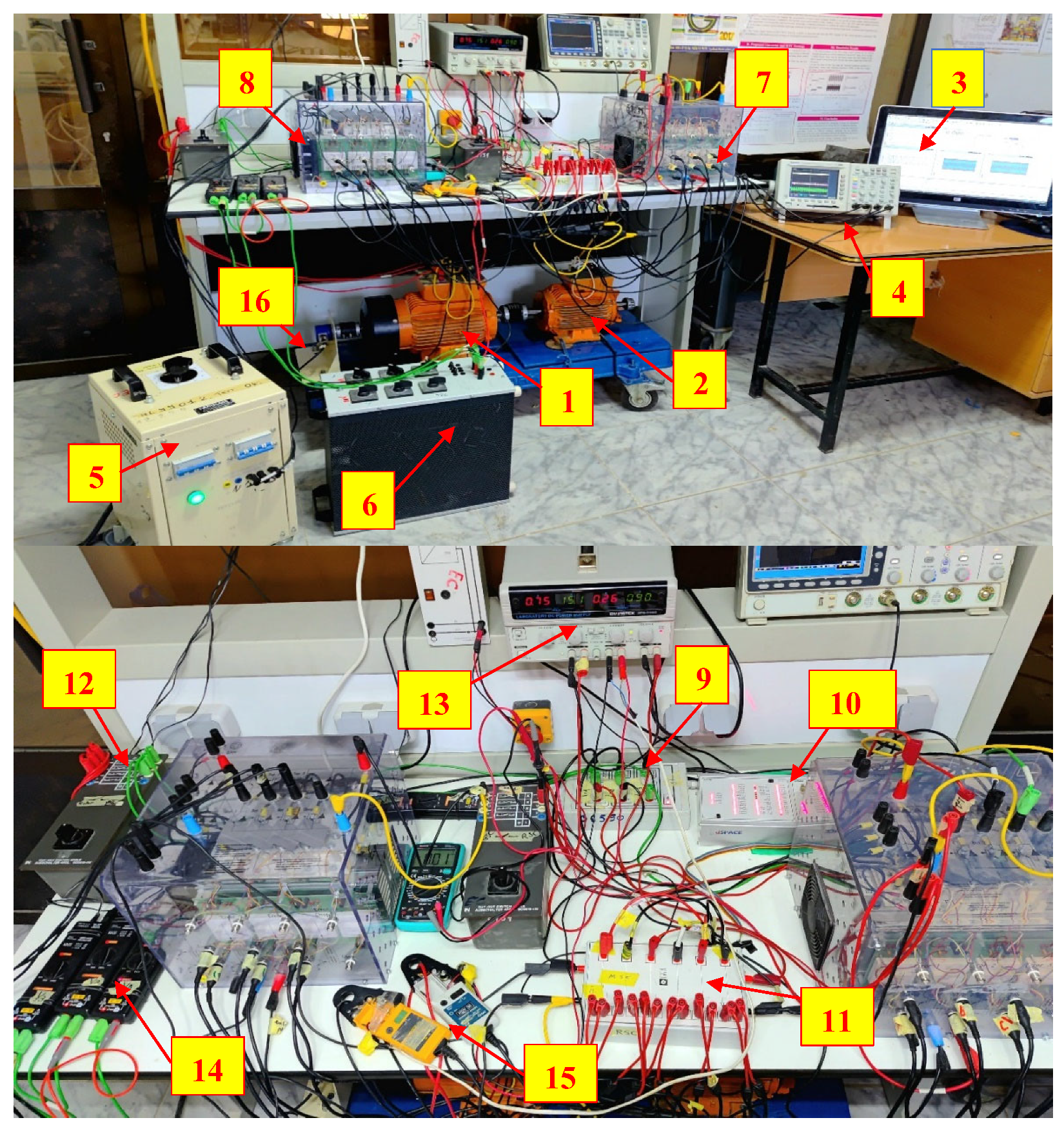
6. Experimental Results
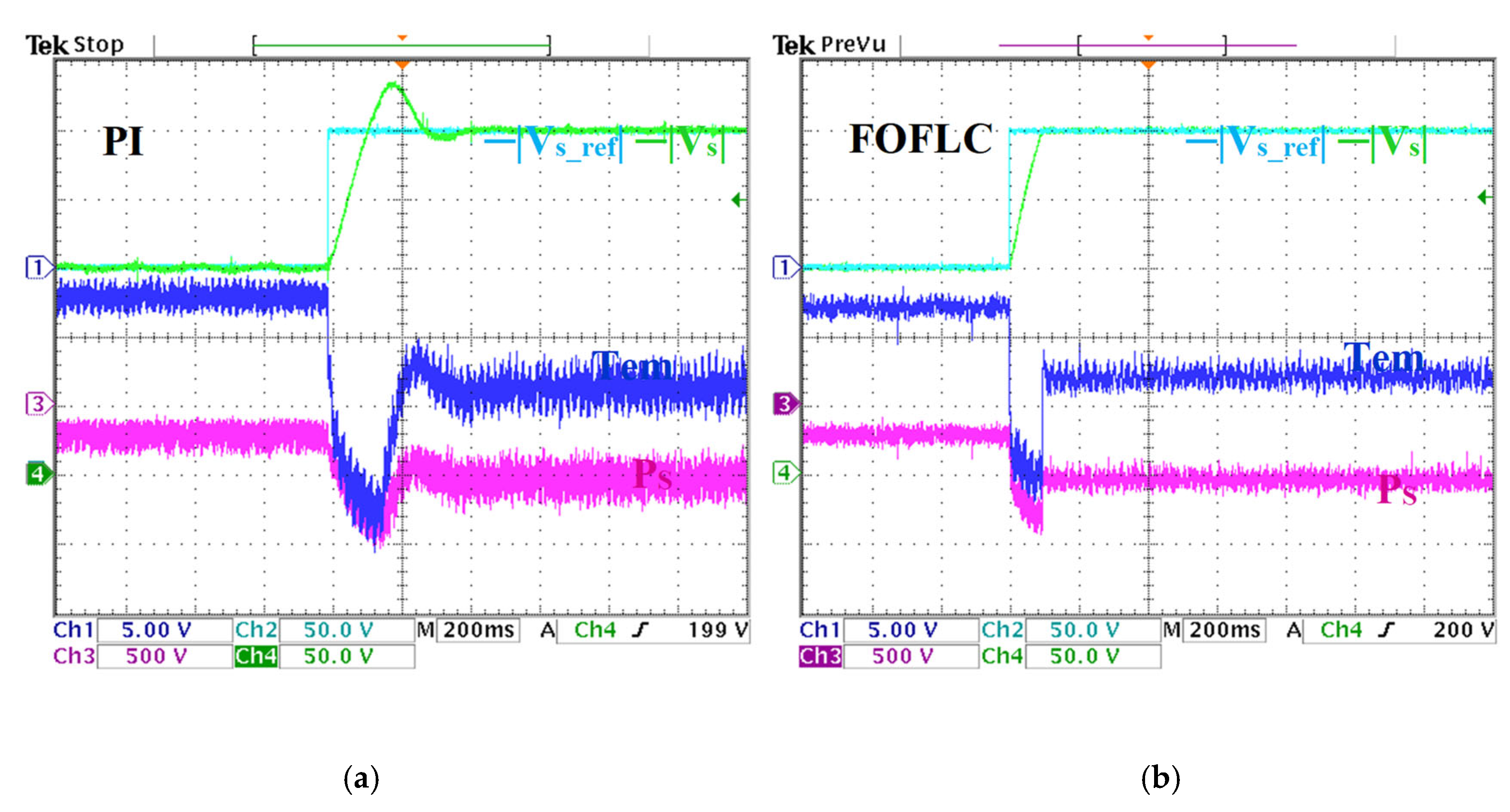
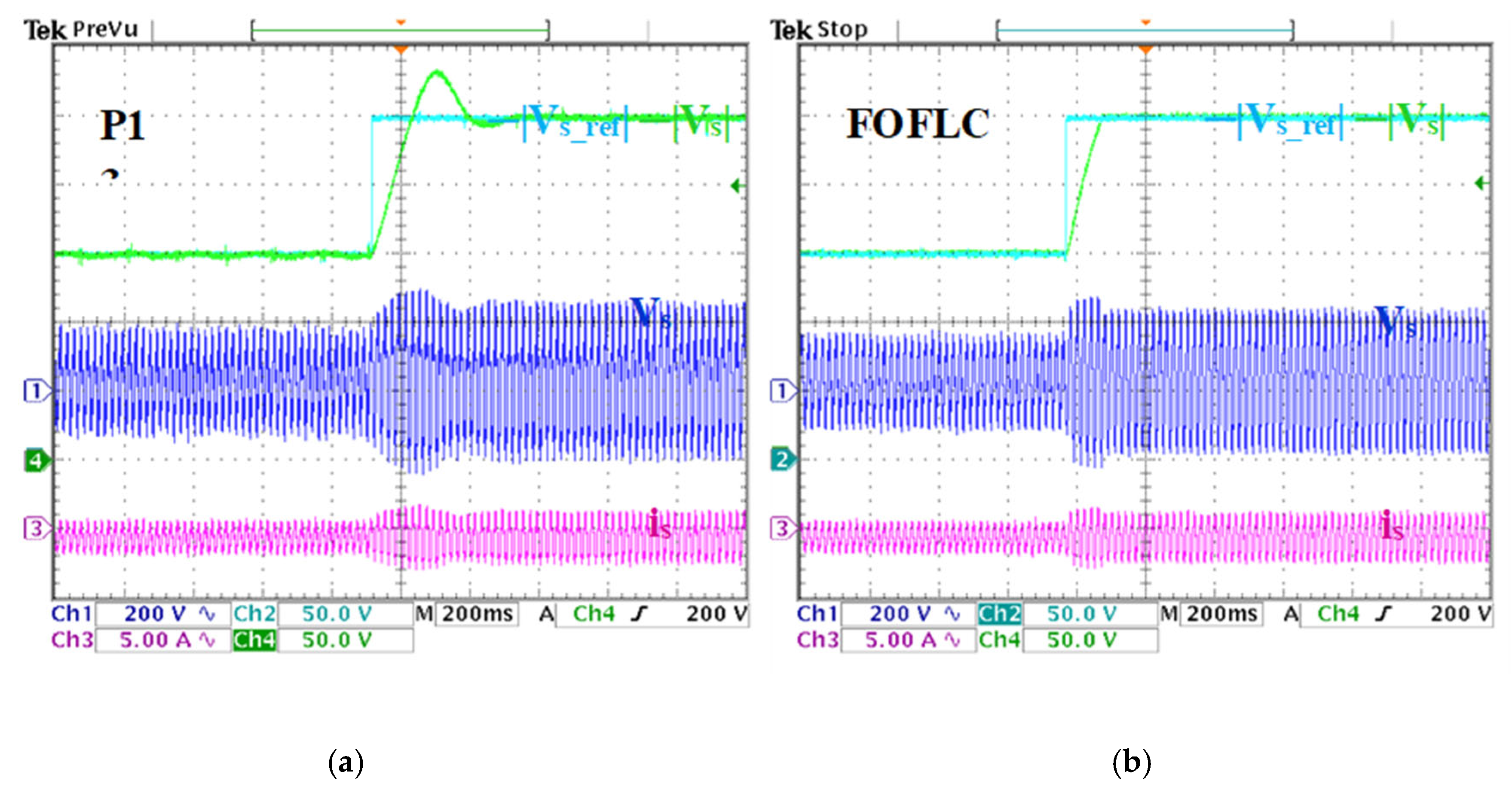
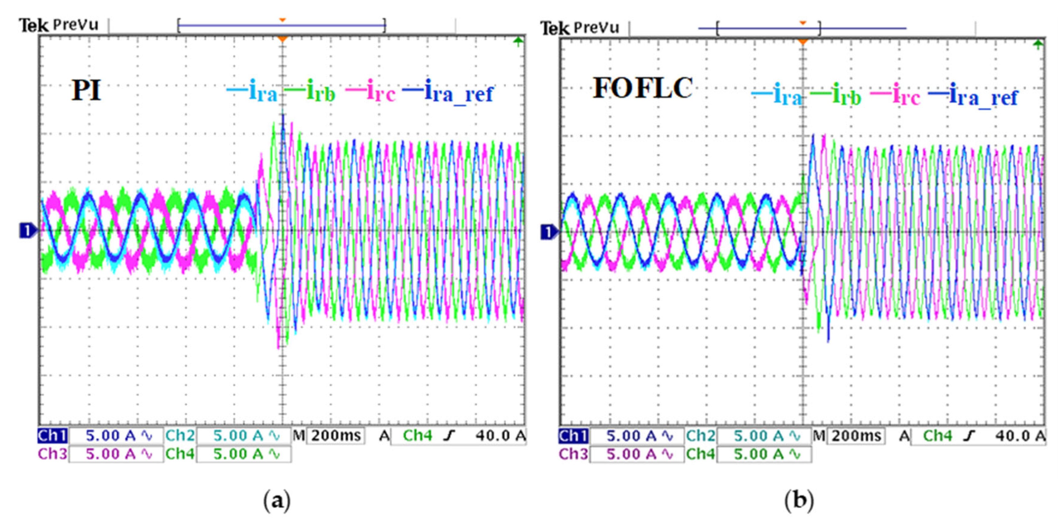
6.1. Reference Stator Voltage Variation Test
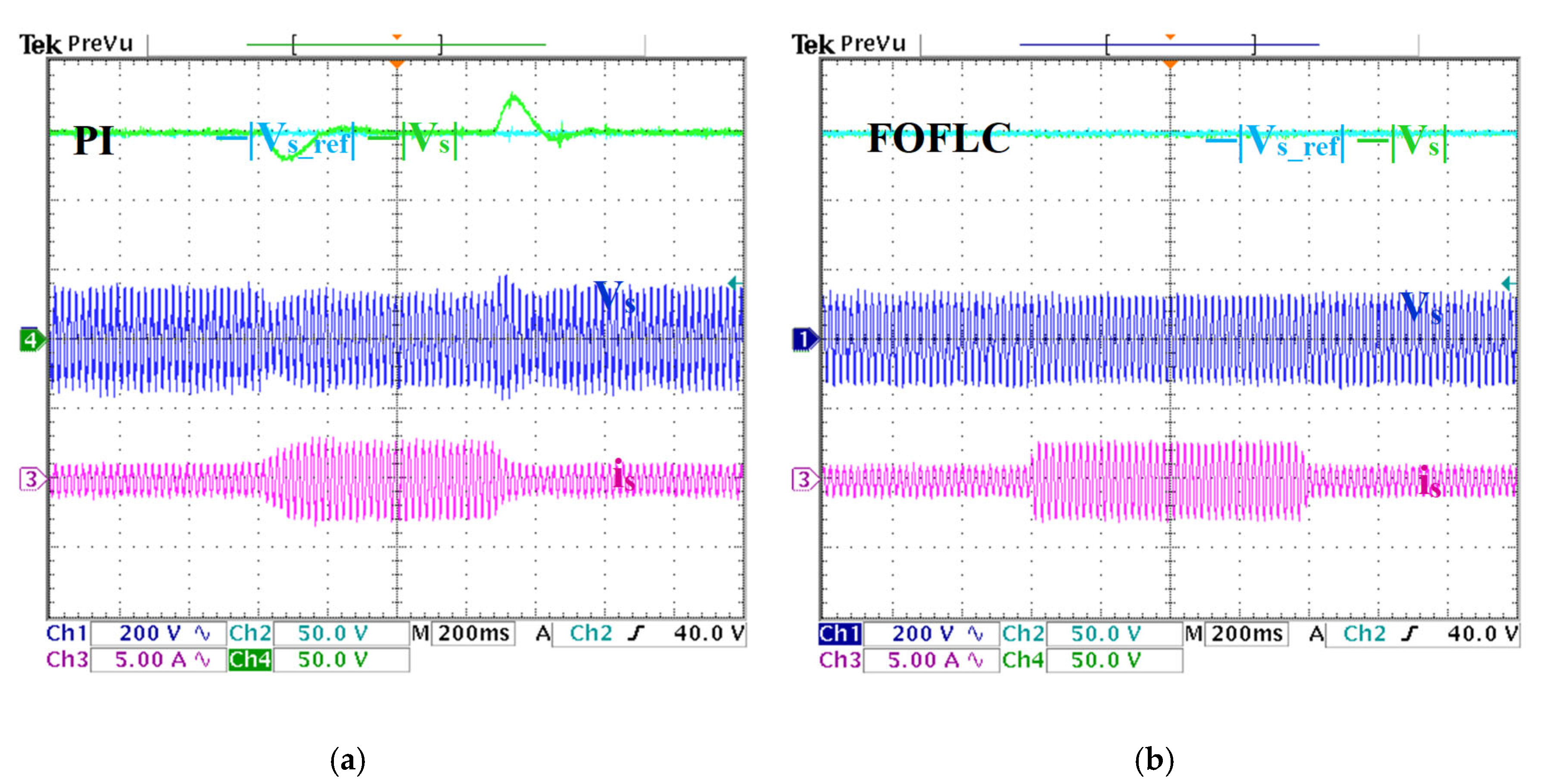
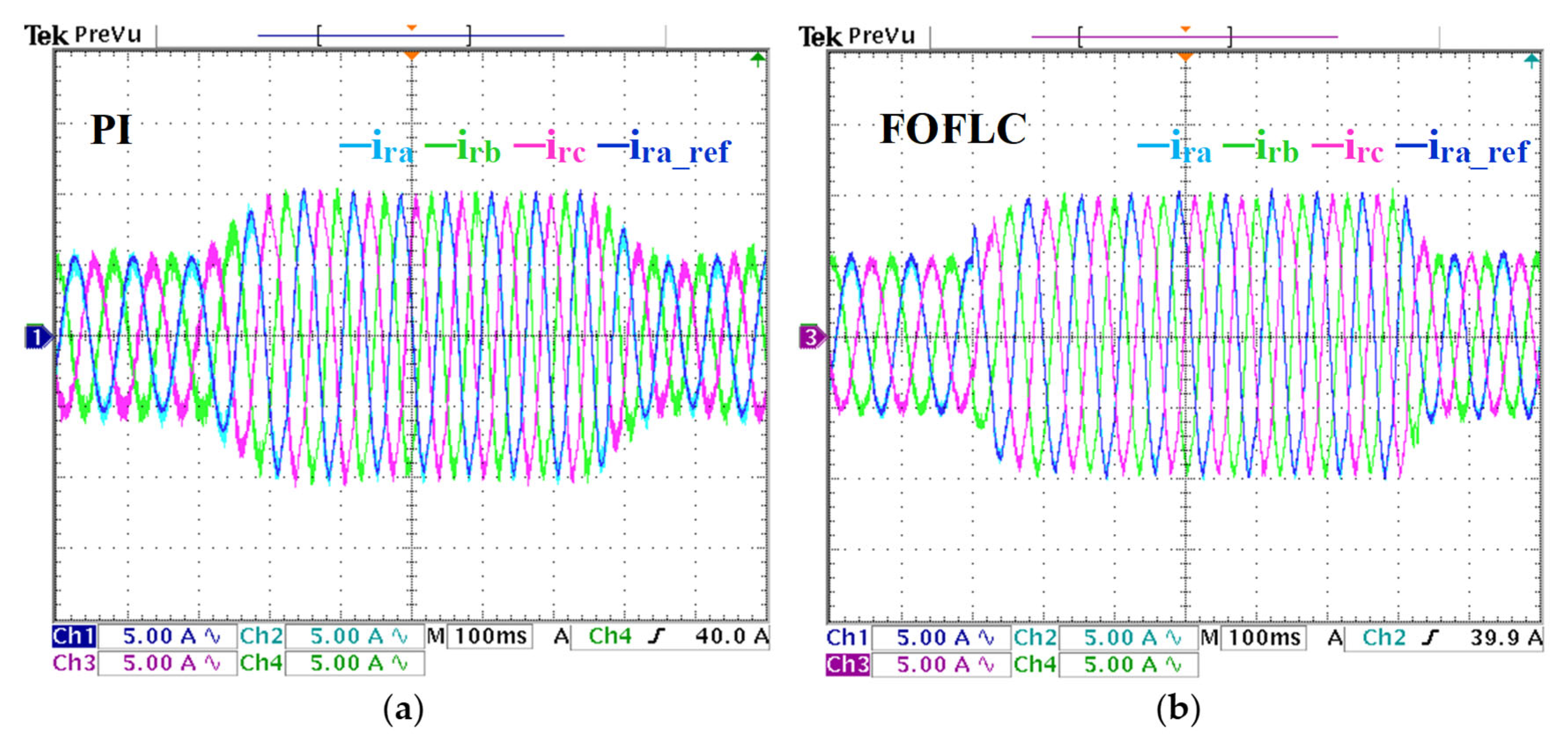
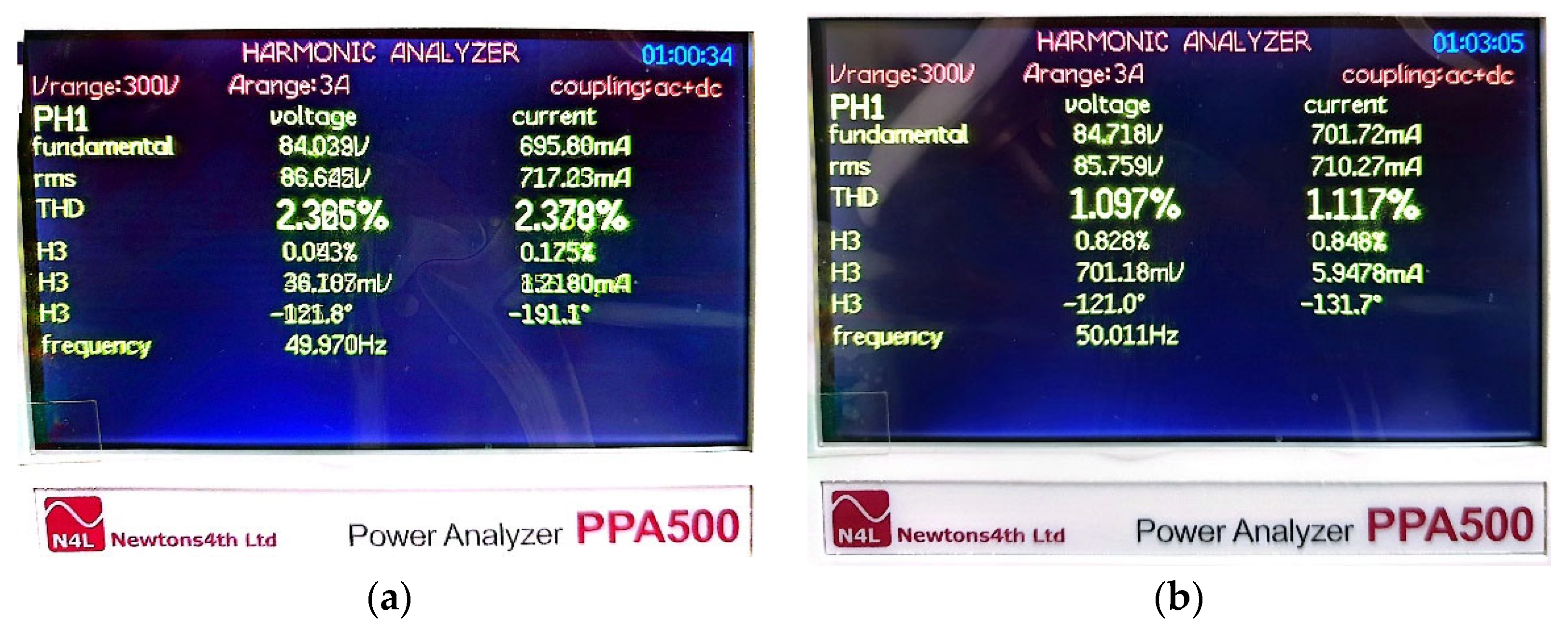
6.2. Load and Speed Variation Test
6.3. Brief Comparative Study with Recent Control Techniques
7. Conclusions
Author Contributions
Funding
Institutional Review Board Statement
Informed Consent Statement
Data Availability Statement
Conflicts of Interest
Abbreviations
| Stator and rotor voltages | |
| Stator and rotor currents | |
| Stator and rotor resistances | |
| Stator and rotor magnetic fluxes | |
| Stator and rotor inductances | |
| Mutual inductance between stator and rotor | |
| dq stator and rotor voltages | |
| dq stator and rotor currents | |
| dq stator and rotor magnetic fluxes | |
| ,, | Pulses of the stator, slip and the rotor |
| Stator, rotor and mechanical position | |
| p | Number of pole pairs |
| Stator time constant | |
| DC bus voltage | |
| Ps, Qs | Stator active et reactive power |
| Tem | Electromagnetic torque |
| Kp, Ki | Proportional-integral (PI) regulator |
| Input and output scaling factors | |
| Fractional integral and differential operators | |
| DFIG | Doubly-Fed Induction Generators |
| FLCs | Fuzzy Logic Controllers |
| FO | Fractional-Order |
| FOFLC | Fractional-Order Fuzzy Logic Controller |
| FOC | Field Oriented Control |
Appendix A
| Parameter | Value | Unit |
|---|---|---|
| Power | 3 | KW |
| Rated speed | 1500 | rpm |
| Frequency | 50 | Hz |
| Stator voltage | 380 | V |
| Number of pole pairs | 2 | |
| Torque | 20 | N·m |
| Lm (Magnetizing inductance) | 0.180 | H |
| Ls (Stator inductance) | 0.255 | H |
| Rs (Stator resistance) | 1.6 | Ω |
| Lr (Rotor inductance) | 0.255 | H |
| Rr (Rotor resistance) | 1.8 | Ω |
| Total inertia | 0.03 | Kg·m2 |
References
- Eftekhari, H.; Al-Obaidi, A.S.M.; Eftekhari, S. Aerodynamic Performance of Vertical and Horizontal Axis Wind Turbines: A Comparison Review. Indones. J. Sci. Technol. 2022, 7, 65–88. [Google Scholar] [CrossRef]
- Krishnan, A.; Al-Obaidi, A.S.M.; Hao, L.C. Towards Sustainable Wind Energy: A Systematic Review of Airfoil and Blade Technologies Over the Past 25 Years for Supporting Sustainable Development Goals (SDGs). Indones. J. Sci. Technol. 2024, 9, 623–656. [Google Scholar] [CrossRef]
- Touaiti, B.; Azza, H.B.; Abdelkader, A.; Abbassi, R.; Farah, A.; Jemli, M. Energy control of on-grid hybrid wind/PV power system using doubly fed induction generator-direct current link topology. Energy Sources Part Recovery Util. Environ. Eff. 2025, 47, 8611–8627. [Google Scholar] [CrossRef]
- Abad, G.; López, J.; Rodríguez, M.A.; Marroyo, L.; Iwanski, G. Doubly Fed Induction Machine: Modeling and Control for Wind Energy Generation, 1st ed.; Wiley: Hoboken, NJ, USA, 2011. [Google Scholar] [CrossRef]
- Patel, K.S.; Makwana, V.H. Modified grid side converter control technique for DFIG connected to nonlinear loads. Energy Sources Part Recovery Util. Environ. Eff. 2024, 46, 15922–15935. [Google Scholar] [CrossRef]
- Dardabi, C.; Álvarez, S.C.; Djebli, A. An Artificial-Neural-Network-Based Direct Power Control Approach for Doubly Fed Induction Generators in Wind Power Systems. Energies 2025, 18, 1989. [Google Scholar] [CrossRef]
- Li, Y.; Sun, W.; Yu, D. RBFNN-based global fast terminal sliding mode control for fully controlled doubly fed induction generator. J. Frankl. Inst. 2024, 361, 107196. [Google Scholar] [CrossRef]
- Misra, H.; Gundavarapu, A.; Jain, A.K. Control Scheme for DC Voltage Regulation of Stand-Alone DFIG-DC System. IEEE Trans. Ind. Electron. 2017, 64, 2700–2708. [Google Scholar] [CrossRef]
- Shukla, R.D.; Tripathi, R.K. Isolated Wind Power Supply System using Double-fed Induction Generator for remote areas. Energy Convers. Manag. 2015, 96, 473–489. [Google Scholar] [CrossRef]
- Chabani, M.S.; Benchouia, M.T.; Golea, A.; Abdealziz, A.Y.; Mossa, M.A. A new sensor-less voltage and frequency control of stand-alone DFIG based dead-beat direct-rotor flux control-experimental validation. ISA Trans. 2025, 158, 715–734. [Google Scholar] [CrossRef]
- Amrane, F.; Francois, B.; Chaiba, A. Experimental investigation of efficient and simple wind-turbine based on DFIG-direct power control using LCL-filter for stand-alone mode. ISA Trans. 2022, 125, 631–664. [Google Scholar] [CrossRef]
- Phan, V.-T.; Nguyen, D.-T.; Trinh, Q.-N.; Nguyen, C.-L.; Logenthiran, T. Harmonics Rejection in Stand-Alone Doubly-Fed Induction Generators With Nonlinear Loads. IEEE Trans. Energy Convers. 2016, 31, 815–817. [Google Scholar] [CrossRef]
- Chabani, M.S.; Benchouia, M.T.; Golea, A.; Becherif, M. Finite-State Predictive Current Control of a Standalone DFIG-Based Wind Power Generation Systems: Simulation and Experimental Analysis. J. Control Autom. Electr. Syst. 2021, 32, 1332–1343. [Google Scholar] [CrossRef]
- Soued, S.; Chabani, M.S.; Becherif, M.; Benchouia, M.T.; Ramadan, H.S.; Betka, A.; Golea, A.; Zouzou, S.E. Experimental behaviour analysis for optimally controlled standalone DFIG system. IET Electr. Power Appl. 2019, 13, 1462–1473. [Google Scholar] [CrossRef]
- Chabani, M.S.; Benchouia, M.T.; Golea, A.; Benmouna, A.; Iqbal, M.; Becherif, M.; Golea, N. Takagi–Sugeno Fuzzy Logic Controller for DFIG Operating in the Stand-Alone Mode: Simulations and Experimental Investigation. Arab. J. Sci. Eng. 2023, 48, 14605–14620. [Google Scholar] [CrossRef]
- Guo, L.; Wang, D.; Peng, Z.; Diao, L. Improved super-twisting sliding mode control of a stand-alone DFIG-DC system with harmonic current suppression. IET Power Electron. 2020, 13, 1311–1320. [Google Scholar] [CrossRef]
- Labdai, S.; Chrifi-Alaoui, L.; Nezli, L.; Hemici, B.; Bussy, P. Implementation of the Adaptive Neural Networks Backstepping Controller for a Stand-Alone DFIG Based WECS. In Proceedings of the 2021 9th International Conference on Systems and Control (ICSC), Caen, France, 24–26 November 2021; pp. 529–535. [Google Scholar] [CrossRef]
- Wang, Y.; Wu, Q.; Yang, R.; Tao, G.; Liu, Z. H∞ current damping control of DFIG based wind farm for sub-synchronous control interaction mitigation. Int. J. Electr. Power Energy Syst. 2018, 98, 509–519. [Google Scholar] [CrossRef]
- Wu, W.J.; Xue, H. Passivity-Based Control Strategies of Doubly Fed Induction Wind Power Generator without Speed Sensors. Appl. Mech. Mater. 2013, 380–384, 3124–3128. [Google Scholar] [CrossRef]
- Mebkhouta, T.; Golea, A.; Boumaraf, R.; Benchouia, T.M.; Karboua, D.; Bajaj, M.; Chebaani, M.; Blazek, V. Sensorless finite set predictive current control with MRAS estimation for optimized performance of standalone DFIG in wind energy systems. Results Eng. 2024, 24, 103622. [Google Scholar] [CrossRef]
- Aboub, H.; Mechouma, R.; Azoui, B.; Labiod, C.; Khechekhouche, A. A New Multicarrier Sinusoidal Pulse Width Modulation (SPWM) Strategy based on Rooted Tree Optimization (RTO) Algorithm for Reducing Total Harmonic Distortion (THD) of Switched-Capacitor Nine-level Inverter in Grid-connected PV systems. Indones. J. Sci. Technol. 2022, 7, 19–36. [Google Scholar] [CrossRef]
- Rajendran, S.; Thangavel, V.; Krishnan, N.; Prabaharan, N. DC Link Voltage Enhancement in DC Microgrid Using PV Based High Gain Converter with Cascaded Fuzzy Logic Controller. Energies 2023, 16, 3928. [Google Scholar] [CrossRef]
- Boucetta, F.; Benchouia, M.T.; Bechrif, M.; Chebani, M.; Golea, A.; Boumaaraf, R. Intelligent Controller to Improve Stator Voltage Regulation Performance of a Standalone DFIG: Real-Time Validation. In Proceedings of the 2024 International Conference on Advances in Electrical and Communication Technologies (ICAECOT), Sétif, Algeria, 1–3 October 2024; pp. 1–6. [Google Scholar] [CrossRef]
- Panda, A.K.; Mikkili, S. FLC based shunt active filter (p–q and Id–Iq) control strategies for mitigation of harmonics with different fuzzy MFs using MATLAB and real-time digital simulator. Int. J. Electr. Power Energy Syst. 2013, 47, 313–336. [Google Scholar] [CrossRef]
- Arifin, S.; Uddin, M.N.; Wang, W. Neuro-Fuzzy Adaptive Direct Torque and Flux Control of a Grid-Connected DFIG-WECS With Improved Dynamic Performance. IEEE Trans. Ind. Appl. 2023, 59, 7692–7700. [Google Scholar] [CrossRef]
- da Silva, J.L. Fuzzy Logic Control with PSO Tuning. In Fuzzy Systems—Theory and Applications; IntechOpen: London, UK, 2021. [Google Scholar] [CrossRef]
- Benchouia, M.T.; Ghadbane, I.; Golea, A.; Srairi, K.; Benbouzid, M.E.H. Implementation of adaptive fuzzy logic and PI controllers to regulate the DC bus voltage of shunt active power filter. Appl. Soft Comput. 2015, 28, 125–131. [Google Scholar] [CrossRef]
- Bao, D.; Liang, X.; Ge, S.S.; Hao, Z.; Hou, B. A framework of adaptive fuzzy control and optimization for nonlinear systems with output constraints. Inf. Sci. 2022, 616, 411–426. [Google Scholar] [CrossRef]
- Anbalagan, P.; Joo, Y.H. Design of memory-based adaptive integral sliding-mode controller for fractional-order T-S fuzzy systems and its applications. J. Frankl. Inst. 2022, 359, 8819–8847. [Google Scholar] [CrossRef]
- Nayak, P.C.; Nayak, B.P.; Prusty, R.C.; Panda, S. Sunflower optimization based fractional order fuzzy PID controller for frequency regulation of solar-wind integrated power system with hydrogen aqua equalizer-fuel cell unit. Energy Sources Part Recovery Util. Environ. Eff. 2021, 47, 9550–9568. [Google Scholar] [CrossRef]
- Huang, S.; Wang, J.; Huang, C.; Zhou, L.; Xiong, L.; Liu, J.; Li, P. A fixed-time fractional-order sliding mode control strategy for power quality enhancement of PMSG wind turbine. Int. J. Electr. Power Energy Syst. 2022, 134, 107354. [Google Scholar] [CrossRef]
- Xie, L.; Wan, D.; Qin, R. Dual-Loop Voltage–Current Control of a Fractional-Order Buck-Boost Converter Using a Fractional-Order PIλ Controller. Fractal Fract. 2023, 7, 256. [Google Scholar] [CrossRef]
- Liu, D.; Han, J.; Chen, G.; Cheng, Y.; Liang, X.; Song, C. Fuzzy self-tuning fractional order PD permanent magnet synchronous motor speed control based on torque compensation. Sci. Rep. 2025, 15, 2141. [Google Scholar] [CrossRef]
- Nako, J.; Psychalinos, C.; Elwakil, A.S. Minimum Active Component Count Design of a PIλDμ Controller and Its Application in a Cardiac Pacemaker System. J. Low Power Electron. Appl. 2023, 13, 13. [Google Scholar] [CrossRef]
- Wase, M.G.; Gebrekirstos, R.F.; Jin, G.-G.; So, G.-B. Fuzzy Gain Scheduling of the Fractional-Order PID Controller for a Continuous Stirred-Tank Reactor Process. Processes 2023, 11, 3275. [Google Scholar] [CrossRef]
- Prabhakaran, A.; Ponnusamy, T.; Thenmozhi; Janarthanan, G. Optimized fractional order PID controller with sensorless speed estimation for torque control in induction motor. Expert Syst. Appl. 2024, 249, 123574. [Google Scholar] [CrossRef]
- Talib, M.; Ibrahim, Z.; Rahim, N.A.; Zulhani, R.; Nordin, N.; Farah, N.; Razali, A. An improved simplified rules Fuzzy Logic Speed Controller method applied for induction motor drive. ISA Trans. 2020, 105, 230–239. [Google Scholar] [CrossRef] [PubMed]
- Puchalapalli, S.; Singh, B. A Single Input Variable FLC for DFIG-Based WPGS in Standalone Mode. IEEE Trans. Sustain. Energy 2020, 11, 595–607. [Google Scholar] [CrossRef]
- Demirbas, S. Self-tuning fuzzy-PI-based current control algorithm for doubly fed induction generator. IET Renew. Power Gener. 2017, 11, 1714–1722. [Google Scholar] [CrossRef]
- Lin, F.-J.; Huang, Y.-S.; Tan, K.-H.; Lu, Z.-H.; Chang, Y.-R. Intelligent-controlled doubly fed induction generator system using PFNN. Neural Comput. Appl. 2013, 22, 1695–1712. [Google Scholar] [CrossRef]
- Dinh, T.N.; Kamal, S.; Pandey, R.K. (Eds.) Fractional-Order System: Control Theory and Applications; MDPI: Basel, Switzerland, 2023. [Google Scholar] [CrossRef]
- Petráš, I. Fractional-Order Nonlinear Systems: Modeling, Analysis and Simulation. In Nonlinear Physical Science; Springer: Berlin/Heidelberg, Germany, 2011. [Google Scholar] [CrossRef]
- Khairudin, M.; Refalda, R.; Yatmono, S.; Pramono, H.S.; Triatmaja, A.K.; Shah, A. The Mobile Robot Control in Obstacle Avoidance Using Fuzzy Logic Controller. Indones. J. Sci. Technol. 2020, 5, 334–351. [Google Scholar] [CrossRef]
- AbdelAty, A.M.; Al-Durra, A.; Zeineldin, H.; El-Saadany, E.F. Improving small-signal stability of inverter-based microgrids using fractional-order control. Int. J. Electr. Power Energy Syst. 2024, 156, 109746. [Google Scholar] [CrossRef]
- Oustaloup, A.; Levron, F.; Mathieu, B.; Nanot, F.M. Frequency-band complex noninteger differentiator: Characterization and synthesis. IEEE Trans. Circuits Syst. Fundam. Theory Appl. 2000, 47, 25–39. [Google Scholar] [CrossRef]


| E | NH | NM | ZE | PM | PH | |
|---|---|---|---|---|---|---|
| PH | ZE | PM | PH | PH | PH | |
| PM | NM | ZE | PM | PM | PH | |
| ZE | NH | NM | ZE | PM | PH | |
| NM | NH | NM | NM | ZE | PM | |
| NH | NH | NH | NH | NM | ZE | |
| PI Controller | FOFLC Controller | |||||||
|---|---|---|---|---|---|---|---|---|
| Vs | Ps | Tem | Is | Vs | Ps | Tem | Is | |
| Response time | 0.394 s | 0.367 s | 0.416 s | 0.394 s | 0.06 s | 0.09 s | 0.097 s | 0.068 s |
| Overshoot | 31 V | 529 W | 12 Nm | - | 0 V | 320 W | 8.7 Nm | - |
| Undershoot | 8 V | 179 W | 3.4 Nm | - | 0 V | 0 W | 0 Nm | - |
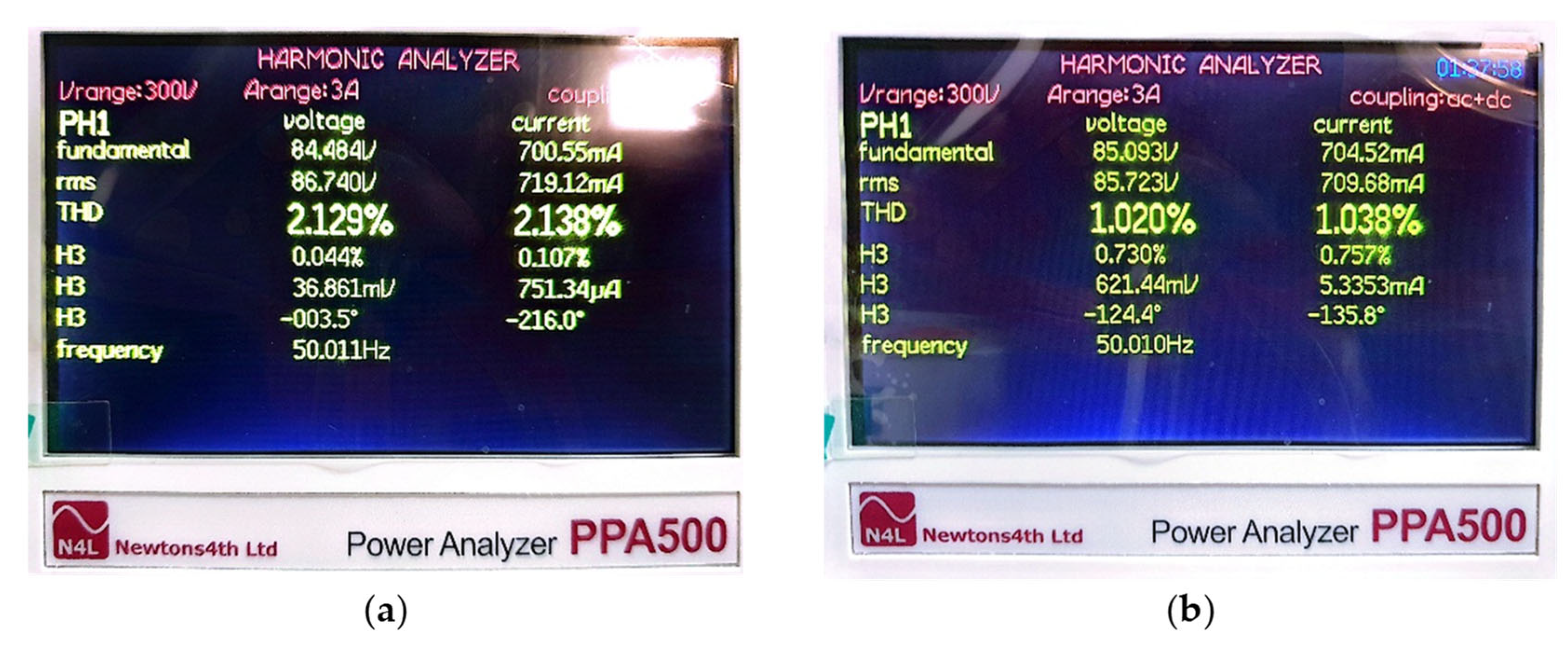
| THD | 2.129% | - | - | 2.138% | 1.02% | - | - | 1.038% |
| TWO (%) | - | 37.88% | 28.75% | - | - | 19.89% | 13.75% | - |
| PI Controller | FOFLC Controller | |||||||
|---|---|---|---|---|---|---|---|---|
| Vs | Ps | Tem | Is | Vs | Ps | Tem | Is | |
| Disturbance rejection | 0.312 s | 0.29 s | 0.198 s | 0.310 s | 0 s | 0.009 s | 0.016 s | 0.021 s |
| Overshoot | 29 V | 140 W | 2.19 N·m | - | 0 V | 0 W | 0.82 N·m | - |
| Undershoot | 7 V | 0 W | 0 N·m | - | 0 V | 0 W | 0 W | - |
| THD | 2.365% | - | - | 2.378% | 1.097% | - | - | 1.117% |
| TWO (%) | - | 32.11% | 20.89% | - | - | 18.32% | 14.66% | - |
| Publication Paper | Technical Methods | Controller | Reference Tacking | Overshoot (%) | THD (%) | Disturbance Rejection |
|---|---|---|---|---|---|---|
| [14] | FOC | PI | ++ | ≈20% | ≈5% | + |
| [12] | FOC | PI-R | ++ | <6% | <5% | ++ |
| [23] | FOC | FLC | ++ | none | ≈5% | +++ |
| [15] | FOC | TS-FLC | +++ | none | 6.29% | +++ |
| [16] | FOC | SMC | ++ | - | ≈5% | ++ |
| [13] | Predictive | PI | ++ | ≈10% | 3.41% | + |
| [8] | VOC | PI | ++ | <7% | - | + |
| [11] | DPC | IP | ++ | ≈8% | ≈4% | ++ |
| [10] | DFC-SVM | PI | ++ | ≈2% | 7.90% | ++ |
| Proposed | FOC | FOFLC | +++ | ≈0% | ≈1.1% | +++ |
Disclaimer/Publisher’s Note: The statements, opinions and data contained in all publications are solely those of the individual author(s) and contributor(s) and not of MDPI and/or the editor(s). MDPI and/or the editor(s) disclaim responsibility for any injury to people or property resulting from any ideas, methods, instructions or products referred to in the content. |
© 2025 by the authors. Licensee MDPI, Basel, Switzerland. This article is an open access article distributed under the terms and conditions of the Creative Commons Attribution (CC BY) license (https://creativecommons.org/licenses/by/4.0/).
Share and Cite
Boucetta, F.; Benchouia, M.T.; Benmouna, A.; Chebani, M.; Golea, A.; Becherif, M.; Saci Chabani, M. Design and Implementation of a Comparative Study of Fractional-Order Fuzzy Logic and Conventional PI Controller for Optimizing Stand-Alone DFIG Performance in Wind Energy Systems. Sci 2025, 7, 80. https://doi.org/10.3390/sci7020080
Boucetta F, Benchouia MT, Benmouna A, Chebani M, Golea A, Becherif M, Saci Chabani M. Design and Implementation of a Comparative Study of Fractional-Order Fuzzy Logic and Conventional PI Controller for Optimizing Stand-Alone DFIG Performance in Wind Energy Systems. Sci. 2025; 7(2):80. https://doi.org/10.3390/sci7020080
Chicago/Turabian StyleBoucetta, Fella, Mohamed Toufik Benchouia, Amel Benmouna, Mohamed Chebani, Amar Golea, Mohamed Becherif, and Mohammed Saci Chabani. 2025. "Design and Implementation of a Comparative Study of Fractional-Order Fuzzy Logic and Conventional PI Controller for Optimizing Stand-Alone DFIG Performance in Wind Energy Systems" Sci 7, no. 2: 80. https://doi.org/10.3390/sci7020080
APA StyleBoucetta, F., Benchouia, M. T., Benmouna, A., Chebani, M., Golea, A., Becherif, M., & Saci Chabani, M. (2025). Design and Implementation of a Comparative Study of Fractional-Order Fuzzy Logic and Conventional PI Controller for Optimizing Stand-Alone DFIG Performance in Wind Energy Systems. Sci, 7(2), 80. https://doi.org/10.3390/sci7020080