

A Simulation of the Biomechanical Behavior of Orthodontic Miniscrews for Infrazygomatic Anchorage: An In Vitro Study

 , , and
Abstract
1. Introduction
2. Materials and Methods
- -
- Deformation angle: the angle described by the long axes of the two screws (Figure 2);
- -
- Linear distance between the tips of the miniscrews (Figure 3).
2.1. Statistical Analysis
2.1.1. Power Analysis
2.1.2. Repeatability
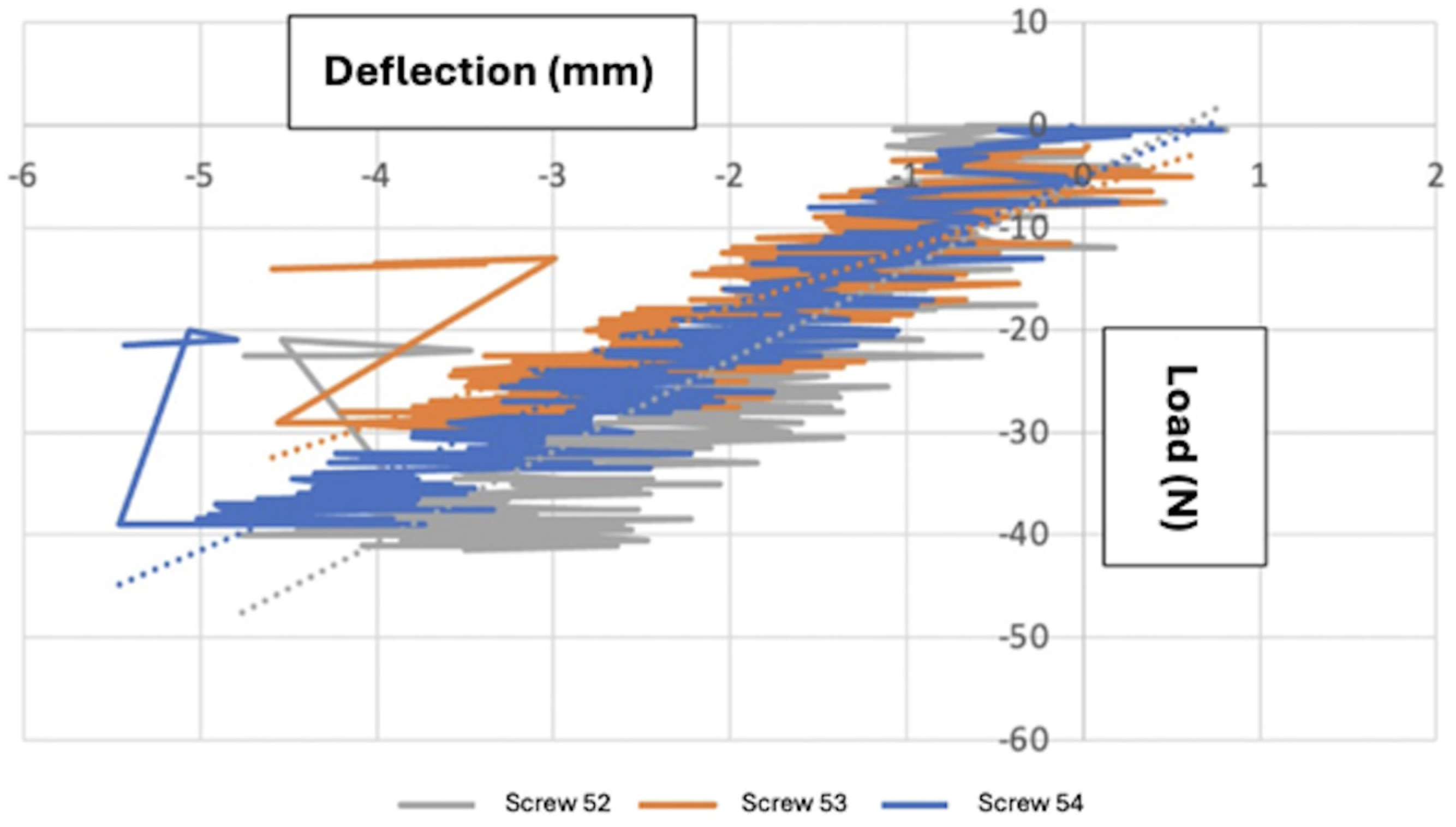
2.1.3. Load–Deflection Curve
2.1.4. Descriptive Statistical Analysis (Mean, Standard Deviation, Minimum, and Maximum) for Load and Deformation
2.1.5. Non-Parametric Single-Sample
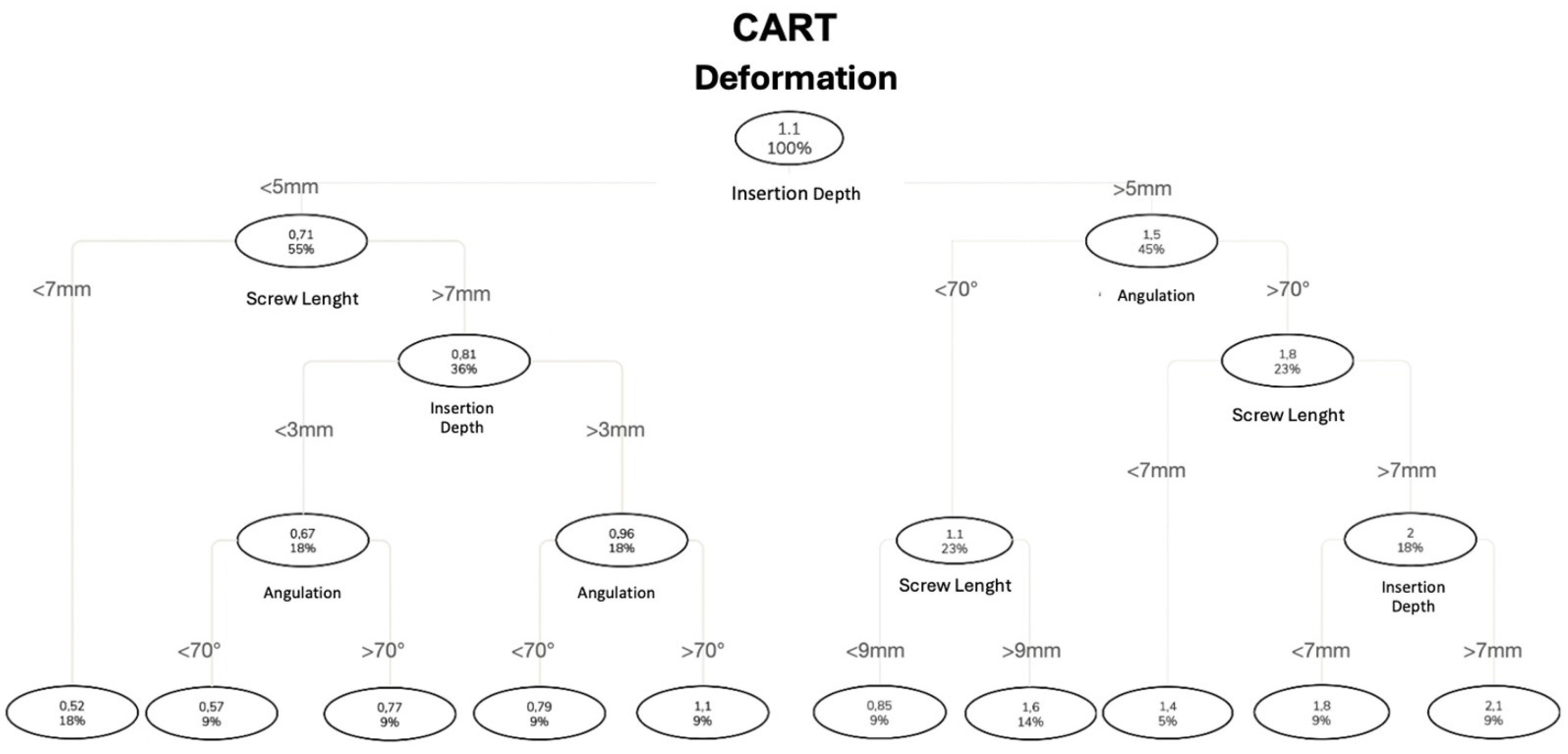
2.1.6. CART
3. Results
3.1. Power Analysis
3.2. Repeatability
3.3. Load–Deflection Curve
3.4. Descriptive Statistics (Mean, Standard Deviation, Minimum, and Maximum) for Maximum Yield Load
3.5. CART for Maximum Yield Load
3.6. Descriptive Statistics (Mean, Standard Deviation, Minimum, and Maximum) for Deformation
3.7. Non-Parametric Single-Sample Tests
3.8. CART for Deformation
4. Discussion
5. Conclusions
- -
- The design of the miniscrews and their insertion method statistically and significantly influence the biomechanical properties of the system.
- -
- The parameter of maximum yield load statistically and significantly increases with the increasing insertion depth.
- -
- The parameter of maximum yield load statistically and significantly decreases with the increasing distance between the support and the point of force application.
- -
- The parameter of deformation statistically and significantly increases with the increasing length of the miniscrew and the leverage arm.
- -
- No statistically significant differences were found between insertion angles of 60° or 80°.
- -
- It is advisable to seek the maximum insertion depth and reduce the distance between the support and the point of force application while maintaining compatibility with the patient’s biomechanical needs and anatomical characteristics.
- -
- Clinically, all of the miniscrews demonstrated sufficient resistance to commonly applied orthodontic loads, confirming their ability to withstand forces typically used in clinical practice. Moreover, to minimize tissue interference, inflammatory processes and patient discomfort, it is preferable to insert the screw in a way that leaves a small portion outside of the bone and mucosa.
Author Contributions
Funding
Institutional Review Board Statement
Informed Consent Statement
Data Availability Statement
Conflicts of Interest
References
- Lima, A., Jr.; Domingos, R.G.; Cunha Ribeiro, A.N.; Rino Neto, J.; de Paiva, J.B. Safe sites for orthodontic miniscrew insertion in the infrazygomatic crest area in different facial types: A tomographic study. Am. J. Orthod. Dentofac. Orthop. 2022, 161, 37–45. [Google Scholar] [CrossRef] [PubMed]
- Lim, S.-A.; Cha, J.-Y.; Hwang, C.-J. Insertion Torque of Orthodontic Miniscrews According to Changes in Shape, Diameter and Length. Angle Orthod. 2008, 78, 234–240. [Google Scholar] [CrossRef] [PubMed]
- Ajami, S.; Mina, A.; Nabavizadeh, S.A. Stress distributions of a bracket type orthodontic miniscrew and the surrounding bone under moment loadings: Three-dimensional finite element analysis. J. Orthod. Sci. 2016, 5, 64–69. [Google Scholar] [CrossRef] [PubMed]
- Chung, K.; Kim, S.-H.; Kook, Y. C-orthodontic microimplant for distalization of mandibular dentition in Class III correction. Angle Orthod. 2005, 75, 119–128. [Google Scholar] [CrossRef] [PubMed]
- Mesko, M.E.; Skupien, J.A.; Valentini, F.; Pereira-Cenci, T. Can we close large prosthetic space with orthodontics? Int. J. Orthod. Milwaukee 2013, 24, 41–44. [Google Scholar] [PubMed]
- Kuroda, S.; Tanaka, E. Risks and complications of miniscrew anchorage in clinical orthodontics. Jpn. Dent. Sci. Rev. 2014, 50, 79–85. [Google Scholar] [CrossRef]
- Büchter, A.; Wiechmann, D.; Koerdt, S.; Wiesmann, H.P.; Piffko, J.; Meyer, U. Load-related implant reaction of mini-implants used for orthodontic anchorage. Clin. Oral Implant. Res. 2005, 16, 473–479. [Google Scholar] [CrossRef] [PubMed]
- Cheng, S.-J.; Tseng, I.-Y.; Lee, J.-J.; Kok, S.-H. A prospective study of the risk factors associated with failure of mini-implants used for orthodontic anchorage. Int. J. Oral Maxillofac. Implant. 2004, 19, 100–106. [Google Scholar]
- Kravitz, N.D.; Kusnoto, B. Risks and complications of orthodontic miniscrews. Am. J. Orthod. Dentofac. Orthop. 2007, 131, S43–S51. [Google Scholar] [CrossRef] [PubMed]
- Jia, X.; Huang, X. Morphometric analysis of the infrazygomatic crest zone in 84 mini-implants using cone-beam CT. Chin. J. Stomatol. 2018, 53, 8–12. [Google Scholar]
- Liou, E.J.; Chen, P.-H.; Wang, Y.-C.; Lin, J.C.-Y. A computed tomographic image study on the thickness of the infrazygomatic crest of the maxilla and its clinical implications for miniscrew insertion. Am. J. Orthod. Dentofac. Orthop. 2007, 131, 352–356. [Google Scholar] [CrossRef] [PubMed]
- Jia, X.; Chen, X.; Huang, X. Influence of orthodontic mini-implant penetration of the maxillary sinus in the infrazygomatic crest region. Am. J. Orthod. Dentofac. Orthop. 2018, 153, 656–661. [Google Scholar] [CrossRef] [PubMed]
- Du, B.; Zhu, J.; Li, L.; Fan, T.; Tan, J.; Li, J. Bone depth and thickness of different infrazygomatic crest miniscrew insertion paths between the first and second maxillary molars for distal tooth movement: A 3-dimensional assessment. Am. J. Orthod. Dentofac. Orthop. 2021, 160, 113–123. [Google Scholar] [CrossRef] [PubMed]
- Vargas, E.O.A.; de Lima, R.L.; Nojima, L.I. Mandibular buccal shelf and infrazygomatic crest thicknesses in patients with different vertical facial heights. Am. J. Orthod. Dentofac. Orthop. 2020, 158, 349–356. [Google Scholar] [CrossRef] [PubMed]
- Colonna, A.; Drudi, M.; Spedicato, G.A.; Mollica, F.; Mazzanti, V.; Paoletto, E.; Maino, G.; Siciliani, G.; Lombardo, L. Assessment of stiffness and load deflection of orthodontic miniscrews used for palatal anchorage: An in vitro biomechanical study. Int. Orthod. 2020, 18, 809–819. [Google Scholar] [CrossRef] [PubMed]
- Pithon, M.M.; Nojima, L.I.; Nojima, M.G.; Ruellas, A. Assessment of flexural strength and fracture of orthodontic mini-implants. Rev. Dent. Press Ortod. Ortop. Facial 2008, 13, 128–133. [Google Scholar] [CrossRef]
- Palone, M.; Darsiè, A.; Maino, G.B.; Siciliani, G.; Spedicato, G.A.; Lombardo, L. Analysis of biological and structural factors implicated in the clinical success of orthodontic miniscrews at posterior maxillary interradicular sites. Clin. Oral Investig. 2022, 26, 3523–3532. [Google Scholar] [CrossRef] [PubMed]
- Chang, C.H.; Lin, J.-H.; Roberts, W.E. Success of infrazygomatic crest bone screws: Patient age, insertion angle, sinus penetration, and terminal insertion torque. Am. J. Orthod. Dentofac. Orthop. 2022, 161, 783–790. [Google Scholar] [CrossRef] [PubMed]


| Variables | |
|---|---|
| Length of the working part of the miniscrews | 6 mm |
| 8 mm | |
| 10 mm | |
| Miniscrew inclination relative to the support | 60° |
| 80° | |
| Insertion depth | 2 mm |
| 4 mm | |
| 6 mm | |
| 8 mm | |
| Support thickness | 2 mm |
| 6 mm | |
| Sample Combination | |||||
|---|---|---|---|---|---|
| Sample Combination | Working Part Length (mm) | Diameter (mm) | Inclination (°) | Insertion Depth (mm) | Support Thickness (mm) |
| 1 | 6 | 2 | 80 | 6 | 6 |
| 2 | 6 | 2 | 60 | 6 | 6 |
| 3 | 8 | 2 | 80 | 6 | 6 |
| 4 | 8 | 2 | 60 | 6 | 6 |
| 5 | 8 | 2 | 80 | 8 | 6 |
| 6 | 8 | 2 | 60 | 8 | 6 |
| 7 | 10 | 2 | 80 | 6 | 6 |
| 8 | 10 | 2 | 60 | 6 | 6 |
| 9 | 10 | 2 | 80 | 8 | 6 |
| 10 | 10 | 2 | 60 | 8 | 6 |
| 11 | 6 | 2 | 80 | 2 | 2 |
| 12 | 6 | 2 | 60 | 2 | 2 |
| 13 | 6 | 2 | 80 | 4 | 2 |
| 14 | 6 | 2 | 60 | 4 | 2 |
| 15 | 8 | 2 | 80 | 2 | 2 |
| 16 | 8 | 2 | 60 | 2 | 2 |
| 17 | 8 | 2 | 80 | 4 | 2 |
| 18 | 8 | 2 | 60 | 4 | 2 |
| 19 | 10 | 2 | 80 | 2 | 2 |
| 20 | 10 | 2 | 60 | 2 | 2 |
| 21 | 10 | 2 | 80 | 4 | 2 |
| 22 | 10 | 2 | 60 | 4 | 2 |
| Sample Combination | Miniscrew | Sample Load Values | Descriptive Load Statistics | ||||||
|---|---|---|---|---|---|---|---|---|---|
| Screw 1 | Screw 2 | Screw 3 | Observations (N) | Mean (N) | SD (N) | Min (N) | Max (N) | ||
| Force (N) | Force (N) | Force (N) | |||||||
| 1 | 2 × 6 80° 6 mm | 200.5 | 201 | 212.5 | 3 | 204.7 | 6.8 | 200.5 | 212.5 |
| 2 | 2 × 6 60° 6 mm | 293.5 | 169.5 | 223.5 | 3 | 228.8 | 62.2 | 169.5 | 293.5 |
| 3 | 2 × 8 60° 6 mm | 83 | 94 | 99 | 3 | 92 | 8.2 | 83 | 99 |
| 4 | 2 × 8 60° 8 mm | 162.5 | 178 | 115.5 | 3 | 152 | 32.5 | 115.5 | 178 |
| 5 | 2 × 8 80° 8 mm | 161 | 241.5 | 191.5 | 3 | 198 | 40.6 | 161 | 241.5 |
| 6 | 2 × 8 80° 6 mm | 108 | 93.5 | 109.5 | 3 | 103.7 | 8.8 | 93.5 | 109.5 |
| 7 | 2 × 10 80° 6 mm | 81.5 | 106 | 80.5 | 3 | 89.3 | 14.4 | 80.5 | 106 |
| 8 | 2 × 10 80° 8 mm | 99.5 | 100 | 111 | 3 | 103.5 | 6.5 | 99.5 | 111 |
| 9 | 2 × 10 60° 6 mm | 59.5 | 81.5 | 76 | 3 | 72.3 | 11.4 | 59.5 | 81.5 |
| 10 | 2 × 10 60° 8 mm | 122.5 | 87 | 98.5 | 3 | 102.7 | 18.1 | 87 | 122.5 |
| 11 | 2 × 6 60° 4 mm | 58.5 | 62.5 | 48 | 3 | 56.3 | 7.5 | 48 | 62.5 |
| 12 | 2 × 6 60° 2 mm | 24 | 38.5 | 58 | 3 | 40.2 | 17.1 | 24 | 58 |
| 13 | 2 × 6 80° 4 mm | 139.5 | 120.5 | 97 | 3 | 119 | 21.3 | 97 | 139.5 |
| 14 | 2 × 6 80° 2 mm | 48.5 | 55.5 | 36.5 | 3 | 46.8 | 9.6 | 36.5 | 55.5 |
| 15 | 2 × 8 60° 4 mm | 57 | 60 | 62.5 | 3 | 59.8 | 2.8 | 57 | 62.5 |
| 16 | 2 × 8 60° 2 mm | 32 | 24.5 | 34.5 | 3 | 30.3 | 5.2 | 24.5 | 34.5 |
| 17 | 2 × 8 80° 4 mm | 82 | 69 | 81 | 3 | 77.3 | 7.2 | 69 | 82 |
| 18 | 2 × 8 80° 2 mm | 41.5 | 29.5 | 39 | 3 | 36.7 | 6.3 | 29.5 | 41.5 |
| 19 | 2 × 10 60° 2 mm | 24.5 | 22.5 | 17.5 | 3 | 21.5 | 3.6 | 17.5 | 24.5 |
| 20 | 2 × 10 60° 4 mm | 43 | 52 | 49.5 | 3 | 48.2 | 4.6 | 43 | 52 |
| 21 | 2 × 10 80° 2 mm | 30.5 | 31 | 32 | 3 | 31.2 | 0.8 | 30.5 | 32 |
| 22 | 2 × 10 80° 4 mm | 55 | 54.5 | 51.5 | 3 | 53.7 | 1.9 | 51.5 | 55 |
| Total Observations | 22 | 22 | 22 | 66 | |||||
| Sample Deformation Values | Descriptive Deformation Statistics | ||||||||
|---|---|---|---|---|---|---|---|---|---|
| Tip-to-Tip Linear Distance | |||||||||
| Sample Combinations | Miniscrews | Screw 1 (mm) | Screw 2 (mm) | Screw 3 (mm) | Observations (N) | Mean (mm) | SD (mm) | Min (mm) | Max (mm) |
| 1 | 2 × 6 80° 6 mm | 1.56 | 1.14 | 1.4 | 3 | 1.37 | 0.21 | 1.14 | 1.56 |
| 2 | 2 × 6 60° 6 mm | 0.74 | 0.8 | 0.64 | 3 | 0.73 | 0.08 | 0.64 | 0.8 |
| 3 | 2 × 8 60° 6 mm | 0.27 | 1.5 | 0.37 | 3 | 0.71 | 0.68 | 0.27 | 1.5 |
| 4 | 2 × 8 60° 8 mm | 0.72 | 0.99 | 1.6 | 3 | 1.1 | 0.45 | 0.72 | 1.6 |
| 5 | 2 × 8 80° 8 mm | 2.53 | 1.99 | 1.22 | 3 | 1.91 | 0.66 | 1.22 | 2.53 |
| 6 | 2 × 8 80° 6 mm | 2.64 | 2 | 1.03 | 3 | 1.89 | 0.81 | 1.03 | 2.64 |
| 7 | 2 × 10 80° 6 mm | 1.84 | 2.19 | 1.4 | 3 | 1.81 | 0.4 | 1.4 | 2.19 |
| 8 | 2 × 10 80° 8 mm | 3.24 | 1.45 | 2.09 | 3 | 2.26 | 0.91 | 1.45 | 3.24 |
| 9 | 2 × 10 60° 6 mm | 2.01 | 0.52 | 1.75 | 3 | 1.43 | 0.8 | 0.52 | 2.01 |
| 10 | 2 × 10 60° 8 mm | 1.87 | 2.08 | 1.08 | 3 | 1.68 | 0.53 | 1.08 | 2.08 |
| 11 | 2 × 6 60° 4 mm | 0.59 | 0.6 | 0.38 | 3 | 0.52 | 0.12 | 0.38 | 0.6 |
| 12 | 2 × 6 60° 2 mm | 0.31 | 0.65 | 0.4 | 3 | 0.45 | 0.18 | 0.31 | 0.65 |
| 13 | 2 × 6 80° 4 mm | 0.93 | 0.19 | 0.4 | 3 | 0.51 | 0.38 | 0.19 | 0.93 |
| 14 | 2 × 6 80° 2 mm | 0.61 | 0.22 | 0.9 | 3 | 0.58 | 0.34 | 0.22 | 0.9 |
| 15 | 2 × 8 60° 4 mm | 0.86 | 0.74 | 0.28 | 3 | 0.63 | 0.31 | 0.28 | 0.86 |
| 16 | 2 × 8 60° 2 mm | 0.66 | 0.34 | 0.51 | 3 | 0.5 | 0.16 | 0.34 | 0.66 |
| 17 | 2 × 8 80° 4 mm | 1.08 | 1.38 | 0.66 | 3 | 1.04 | 0.36 | 0.66 | 1.38 |
| 18 | 2 × 8 80° 2 mm | 1.01 | 1.22 | 0.41 | 3 | 0.88 | 0.42 | 0.41 | 1.22 |
| 19 | 2 × 10 60° 2 mm | 0.73 | 0.71 | 0.48 | 3 | 0.64 | 0.14 | 0.48 | 0.73 |
| 20 | 2 × 10 60° 4 mm | 0.67 | 0.87 | 1.35 | 3 | 0.96 | 0.35 | 0.67 | 1.35 |
| 21 | 2 × 10 80° 2 mm | 0.73 | 0.49 | 0.77 | 3 | 0.66 | 0.15 | 0.49 | 0.77 |
| 22 | 2 × 10 80° 4 mm | 1.22 | 1.17 | 1.2 | 3 | 1.2 | 0.03 | 1.17 | 1.22 |
| Total Observations | 22 | 22 | 22 | 66 | |||||
| Sample Deformation Values | Descriptive Deformation Statistics | ||||||||
|---|---|---|---|---|---|---|---|---|---|
| Deformation Angle | |||||||||
| Sample Combinations | Miniscrews | Screw 1 (°) | Screw 2 (°) | Screw 3 (°) | Observations (N) | Mean (°) | SD (°) | Min (°) | Max (°) |
| 1 | 2 × 6 80° 6 mm | 3.2 | 4.4 | 7 | 3 | 4.87 | 1.94 | 3.2 | 7 |
| 2 | 2 × 6 60° 6 mm | 0.5 | 4.2 | 4.3 | 3 | 3 | 2.17 | 0.5 | 4.3 |
| 3 | 2 × 8 60° 6 mm | 3 | 1.1 | 4.5 | 3 | 2.87 | 1.7 | 1.1 | 4.5 |
| 4 | 2 × 8 60° 8 mm | 4.8 | 6.1 | 2.9 | 3 | 4.6 | 1.61 | 2.9 | 6.1 |
| 5 | 2 × 8 80° 8 mm | 11.5 | 8.8 | 5.5 | 3 | 8.6 | 3 | 5.5 | 11.5 |
| 6 | 2 × 8 80° 6 mm | 11.9 | 9 | 4.6 | 3 | 8.5 | 3.68 | 4.6 | 11.9 |
| 7 | 2 × 10 80° 6 mm | 8 | 6 | 7.4 | 3 | 7.13 | 1.03 | 6 | 8 |
| 8 | 2 × 10 80° 8 mm | 12.9 | 5.6 | 8.4 | 3 | 8.97 | 3.68 | 5.6 | 12.9 |
| 9 | 2 × 10 60° 6 mm | 7.9 | 2 | 6.9 | 3 | 5.6 | 3.16 | 2.9 | 7.9 |
| 10 | 2 × 10 60° 8 mm | 7.2 | 8.4 | 5.4 | 3 | 7 | 1.51 | 5.4 | 8.4 |
| 11 | 2 × 6 60° 4 mm | 2.9 | 2.8 | 1.8 | 3 | 2.5 | 0.61 | 1.8 | 2.9 |
| 12 | 2 × 6 60° 2 mm | 1.2 | 3.6 | 1.7 | 3 | 2.17 | 1.27 | 1.2 | 3.6 |
| 13 | 2 × 6 80° 4 mm | 3.1 | 1.5 | 2.2 | 3 | 2.27 | 0.8 | 1.5 | 3.1 |
| 14 | 2 × 6 80° 2 mm | 2.8 | 1.9 | 2.9 | 3 | 2.53 | 0.55 | 1.9 | 2.9 |
| 15 | 2 × 8 60° 4 mm | 4.9 | 1 | 2.1 | 3 | 2.67 | 2.01 | 1 | 4.9 |
| 16 | 2 × 8 60° 2 mm | 1.5 | 3.3 | 2 | 3 | 2.27 | 0.93 | 1.5 | 3.3 |
| 17 | 2 × 8 80° 4 mm | 4.6 | 5.4 | 1.8 | 3 | 3.93 | 1.89 | 1.8 | 5.4 |
| 18 | 2 × 8 80° 2 mm | 2.6 | 3.4 | 5.2 | 3 | 3.73 | 1.33 | 2.6 | 5.2 |
| 19 | 2 × 10 60° 2 mm | 3 | 3.2 | 1.9 | 3 | 2.7 | 0.7 | 1.9 | 3.2 |
| 20 | 2 × 10 60° 4 mm | 3.8 | 4.2 | 3.3 | 3 | 3.77 | 0.45 | 3.3 | 4.2 |
| 21 | 2 × 10 80° 2 mm | 3.9 | 3.2 | 1.2 | 3 | 2.77 | 1.4 | 1.2 | 3.9 |
| 22 | 2 × 10 80° 4 mm | 4.8 | 4.6 | 4.5 | 3 | 4.63 | 0.15 | 4.5 | 4.8 |
| Total Observations | 22 | 22 | 22 | 66 | |||||
Disclaimer/Publisher’s Note: The statements, opinions and data contained in all publications are solely those of the individual author(s) and contributor(s) and not of MDPI and/or the editor(s). MDPI and/or the editor(s) disclaim responsibility for any injury to people or property resulting from any ideas, methods, instructions or products referred to in the content. |
© 2025 by the authors. Licensee MDPI, Basel, Switzerland. This article is an open access article distributed under the terms and conditions of the Creative Commons Attribution (CC BY) license (https://creativecommons.org/licenses/by/4.0/).
Share and Cite
Palone, M.; Tucci, D.; Calza, M.; Arveda, N.; Cremonini, F.; Pepe, F.; Lombardo, L. A Simulation of the Biomechanical Behavior of Orthodontic Miniscrews for Infrazygomatic Anchorage: An In Vitro Study. Sci 2025, 7, 64. https://doi.org/10.3390/sci7020064
Palone M, Tucci D, Calza M, Arveda N, Cremonini F, Pepe F, Lombardo L. A Simulation of the Biomechanical Behavior of Orthodontic Miniscrews for Infrazygomatic Anchorage: An In Vitro Study. Sci. 2025; 7(2):64. https://doi.org/10.3390/sci7020064
Chicago/Turabian StylePalone, Mario, Davide Tucci, Marta Calza, Niki Arveda, Francesca Cremonini, Filippo Pepe, and Luca Lombardo. 2025. "A Simulation of the Biomechanical Behavior of Orthodontic Miniscrews for Infrazygomatic Anchorage: An In Vitro Study" Sci 7, no. 2: 64. https://doi.org/10.3390/sci7020064
APA StylePalone, M., Tucci, D., Calza, M., Arveda, N., Cremonini, F., Pepe, F., & Lombardo, L. (2025). A Simulation of the Biomechanical Behavior of Orthodontic Miniscrews for Infrazygomatic Anchorage: An In Vitro Study. Sci, 7(2), 64. https://doi.org/10.3390/sci7020064